David Potočnik, Bojan Dolšak, Miran Ulbin. GAJA: 3D CAD methodology for developing a parametric system for the automatic (re)modeling of the cutting components of compound washer dies[J]. Journal of Zhejiang University Science A, 2013, 14(5): 327-340.
@article{title="GAJA: 3D CAD methodology for developing a parametric system for the automatic (re)modeling of the cutting components of compound washer dies", author="David Potočnik, Bojan Dolšak, Miran Ulbin", journal="Journal of Zhejiang University Science A", volume="14", number="5", pages="327-340", year="2013", publisher="Zhejiang University Press & Springer", doi="10.1631/jzus.A1200245" }
%0 Journal Article %T GAJA: 3D CAD methodology for developing a parametric system for the automatic (re)modeling of the cutting components of compound washer dies %A David Potočnik %A Bojan Dolšak %A Miran Ulbin %J Journal of Zhejiang University SCIENCE A %V 14 %N 5 %P 327-340 %@ 1673-565X %D 2013 %I Zhejiang University Press & Springer %DOI 10.1631/jzus.A1200245
TY - JOUR T1 - GAJA: 3D CAD methodology for developing a parametric system for the automatic (re)modeling of the cutting components of compound washer dies A1 - David Potočnik A1 - Bojan Dolšak A1 - Miran Ulbin J0 - Journal of Zhejiang University Science A VL - 14 IS - 5 SP - 327 EP - 340 %@ 1673-565X Y1 - 2013 PB - Zhejiang University Press & Springer ER - DOI - 10.1631/jzus.A1200245
Abstract: For the designing of cutting-dies is a complex and experience-based process, it is poorly supported by conventional 3D CAD software. Thus, the majority of design activities, including the (re)modeling of those cutting die-components that are directly responsible for performing shaping operations on a sheet-metal stamping part, traditionally still need to be carried-out repetitively, separately, and manually by the designer. To eliminate some of these drawbacks and upgrade the capabilities of conventional 3D CAD software, this paper proposes a new methodology for the development of a parametric system capable of automatically performing a (re)modeling process of compound washer dies’ cutting-components. The presented methodology integrates CATIA V5 built-in modules, including Part Design, Assembly Design and Knowledge Advisor, publication mechanism, and compound cutting die-design knowledge. The system developed by this methodology represents an ‘intelligent’ assembly template composed of two modules GAJA1 and GAJA2, respectively. GAJA1 is responsible for the direct input of the die-design problem regarding the shape, dimensions and material of the stamping part, its extraction in the form of geometric features, and the transferring of relevant design parameters and features to the module GAJA2. GAJA2 interprets the current values for the input parameters and automatically performs the modeling process of cutting die-components, using die-design knowledge and the company’s internal design and manufacturing standards. Experimental results show that this system significantly shortens the modeling-time for cutting the die-components, improves the modeling-quality, and enables the training of inexperienced designers.
Darkslateblue:Affiliate; Royal Blue:Author; Turquoise:Article
Article Content
1. Introduction
The designing of cutting dies is a complex and highly-specialized procedure (Tor et al., 2003) that designates one of the primary tasks during the development of cutting processes. To survive in today’s globalized and highly-competitive environment, there is an urgent need for achieving faster and more cost-efficient die design processes, along with improved product quality. Successful mastering of CAD-technology has become one of the most important ways in this regard. The usage of modern 3D CAD software offers designers significant possibilities for improving the productivity of the design-process, and thus it has also become a well-accepted standard within the die-development industry. Solid modeling allows designers to create precise mathematical and realistic graphical representations of the stamping-dies, whereby the CAD-models can be viewed from any angle at any distance, and any interference between die-components can be easily checked. Unfortunately, most 3D CAD software can only provide transfer of the results from a designer’s reasoning process into a formal geometrical model and, therefore, does not provide the necessary and sufficient design knowledge for supporting engineers during their required design tasks (McMahon and Browne, 1999; Mok et al., 2001; Tay and Gu, 2002; Lin et al., 2008; Lin and Hsu, 2008; Potocnik et al., 2012). This difficulty can be attributed to the limitations of most conventional 3D CAD systems that make them incapable of making decisions based on the functional die-design knowledge that connects the shapes and dimensions of cutting die-components to those of a sheet-metal part’s stamping features (Liu et al., 2004). Therefore, the design must be manually completed, on the basis of functional and procedural knowledge (Bandini and Sartori, 2006).
Some CAD-developers recognized this bottleneck and developed knowledge-based extensions like Progressive Die Wizard on NX, 3DQuickPress® on SolidWorks® and Creo Progressive Die. Since these modules contain libraries of predefined functional features with associated parameters, only a few functions have been extended to automatic design. Thus, the design process of cutting die-components still requires skilled and experienced die designers to interpret the design problem and finally make appropriate decisions. Such modules are, moreover, costly and often beyond the reach of small and medium-sized stamping industries, and incorporate only standard and design rules from specific textbooks and course materials, which quite often do not suit the majority of potential users. On the other hand, stamping companies use diverse CAD packages where knowledge-based extensions are not always provided. Therefore, some developments of cutting die design systems based on knowledge and intelligent engineering have also been studied recently. Choi et al. (1998) developed a 2D CAD system for the blanking or piercing of irregular-shaped sheet metal products, and stator and rotor parts. This system has been implemented in AutoLISP on AutoCAD and is composed of six main modules including input and shape treatment, production feasibility checks, blank layout, strip layout, die layout, and drawing edit modules. Kumar et al. (2008) conducted an expert system for designing blanking dies regarding sheet-metal operations using AutoCAD and AutoLISP. Kumar and Singh (2011) discussed an automated design system for progressive dies, where a production rule knowledge-based system approach was utilized for constructing the system’s 27 modules within AutoCAD. Since the above-mentioned research focused on the development of 2D CAD systems, the development of die design methodologies that can be directly integrated within a 3D CAD environment and would increase their ‘intelligence’, has become a challenging research area. Through such an extension of 3D CAD functionalities, the automation of die design activities could be achieved, and thus the die design process could be greatly optimized. However, very few attempts have been made in this direction due to a lack of understanding regarding the internal mechanisms of 3D CAD systems, and difficulties arising from attempts to standardize complex die-design processes and knowledge. Jia et al. (2011) analysed a structural design tool for punches and dies for the progressive dies of motor-core based on a functional component, using SolidWorks. The proposed tool can complete the design of five classes of punches and dies and generate holes on plates automatically. Other attempts have mainly focused on the design automation of drawing dies. Lin and Hsu (2008) proposed an automated system for drawing die designs, based on built-in modules of CATIA. Lin et al. (2008) developed a parametric design system for drawing dies, with a specific type of die structure, using Pro/ENGINEER, whilst Lin et al. (2009) built structural automated design systems for 3D drawing dies based on functional features within CATIA software. During these attempts the design process for the main components of drawing dies was standardized within a parametric environment. Because the design of each type of stamping die (e.g., cutting or bending and compound or progressive dies) demands the activation of specific knowledge, there is a lack of parametric methodologies that would enable reasoning about specific die-design tasks and then automatically performing actions on this basis within a 3D CAD environment. Therefore, the majority of die-design activities (Chin and Tang, 2002; Tang et al., 2003), including the (re)modeling of those die-components that are directly responsible for performing cutting operations on a sheet-metal stamping part like a washer, traditionally still need to be carried-out repetitively, separately, and manually by the designer. When performing this process a company’s specific design and manufacturing standards must also be taken into consideration. Such reasoning capabilities and rapid action-performances (modeling) on this basis are the properties of expert designers that call for integration within 3D environments in order to optimize the design process of cutting die-components. Therefore, this paper proposes GAJA—a parametric methodology for developing a system that will enable the automatic (re)modeling of cutting die-components. The system will be established using die-design knowledge which is flexibly integrated within a 3D CAD environment.
Features (Shah and Mäntylä, 1995; Stroud and Nagy, 2011) are the generic shapes or characteristics of a product with which engineers can associate certain attributes and knowledge for reasoning about the product (Lin et al., 2009), and therefore provide an excellent basis for formalizing and representing the different types of knowledge involved in the designer’s decision-making activity. Even though cutting die-components are, within a parametric 3D CAD environment, modeled as a composition of geometric features and then stored within separate CAD-part files (Schilling et al., 2006), re-usage of applied knowledge is mostly prevented. The lack of a designer’s time, skill, and experience are reasons why this knowledge is not written in a flexible manner that could enable CAD-systems to automatically solve a wide-range of design problems. Thus, it is especially difficult to reuse and quickly remodel existing cutting die-components in such a way that they will suit any new/different die-design problems regarding the shapes and dimensions, i.e., the properties of the sheet-metal stamping parts’ form-features that they are responsible for producing. The presented methodology resolves this bottleneck of the conventional CAD system through the integration of CATIA V5 built-in modules, including Part Design, Assembly Design, Knowledge Advisor (API), publication mechanism, and cutting die-design knowledge.
The basis for implementing and developing the proposed methodology is by utilizing the parametric nature of modern 3D CAD software, which enables the descriptions of virtual geometric objects’ computer representations, using various types of design parameters (Saridakis and Dentsoras, 2005), the values of which completely describe the constitutive features of stamping parts and cutting die-components. Functional and procedural knowledge relating to features’ behavior can be formalized through associations between design parameters taking the forms of formulas, and IF {condition}, THEN {statement} production rules (Baxter et al., 2007; Bettig and Hoffmann, 2011). Formula Editor and Rule Editor Functions have been exploited to embed related knowledge into the design. The system developed by this methodology is capable of automatically (re)modeling the cutting die-components of a compound-die like a piercing-punch, compound and blanking-matrix, based only on design-problem identification-data input.
2. Problem assessment-traditional designing of cutting die-components
Washers are sheet metal stamping parts commonly used within a variety of industries, and can capture a wide-range of variants (configurations) regarding the properties of their form-features, i.e., their shapes and sizes. Countless compound cutting-dies are therefore employed for fabricating diverse washers’ variants by simultaneously performing, blanking, and piercing operations on a flat material strip, by a single press-stroke. Amongst numerous components of compound cutting-dies, piercing-punch, compound and blanking-matrix, are those components directly responsible for the shaping of washers. The function of cutting die-components design can be written as
. Here, it is worth mentioning that the dimensional tolerances should also be taken into consideration when designing cutting die-components, but this is beyond the scope of this paper.
Each different washer-variant in regard to its shape, size and material represents a new problem regarding the designing of cutting die-components (Fig. 1). When one design problem is solved, some of the functional and procedural design knowledge is stored within individual CAD-part files in the form of corresponding geometrical features, and the values of their associated parameters. Unfortunately, conventional 3D CAD systems fail to capture any deep understanding of the cutting die-components’ design processes, and are thus automatically unable to reuse the existing part-files, and adapt them to new/different design problems. In other words, they are incapable of explaining how those parameters identifying the form and material of a sheet-metal stamping part’s influence on the designing of cutting die-components’ features. Consequently, the modeling of cutting die-components needs to be performed repetitively, separately, and manually by the designer. If a new design problem only requires dimensional modification, the designer has to copy and enter the existing part-files and then perform corresponding adjustments to those dimensional parameters that describe the properties of the cutting die-components’ functional features. Compared to the dimensional change of a geometrical feature, a change in the shape of the feature represents a far more complex task (Kim et al., 2006). Here the reuse of existing designs would mean that the designer has to change the geometrical feature within each individual part-file by first deleting and then manually modeling new shape profiles (2D sketch) for its definition. For this reason, designers usually prefer to create new part-files and start modeling the cutting die-components from the beginning. Exploiting family tables (Kim et al., 2008; Jia et al., 2011) could solve these problems to some degree but the establishment of numerous possible instances for cutting die-components could represent endless activity. Each cutting die-component, for instance, has to be selected individually whilst searching for an appropriate one within a non-transparent database can be a very time-consuming task.
Fig.1 Starting scheme for developing the proposed methodology
It can be summarized that the designer is traditionally obliged to spend much of his/her valuable time on (applying his/her knowledge) setting up parameters’ values, manipulating features, and (re)establishing constraints (geometrical and algebraic) for obtaining adequate 3D CAD models of cutting die-components. Exploiting knowledge of both the domain and the CAD-environment for eliminating the deficiencies of the traditional procedure when modeling cutting die-components would represent a major scientific approach for the establishment of the proposed methodology, and the development of the system.
3. Methodology for developing the system
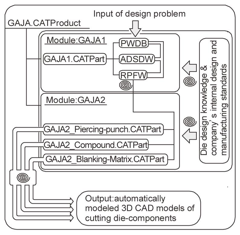
The overall functioning of the system is provided by two modules namely GAJA1 and GAJA2 (Fig. 2). CATIA V5 built-in modules were exploited for the construction of these modules. The Part Design module was used for designing the geometrical features and models, implementing their parameterization, and writing constraining formulas, whilst the integrated publication mechanism was used for transferring the parameters’ values, geometries, and design entities from one module to another.
Fig.2 System’s architecture
The API module was used for the programming of decision constraints in the form of ‘IF-THEN’ rules. Functional and procedural knowledge for designing cutting die-components was obtained from interviews with experts and company’s internal design and manufacturing standards. Since the proposed modules must function simultaneously, the Assembly Design module was exploited for creating the CATIA V5 assembly document GAJA.CATProduct, where the proposed modules would be placed and thus, the system built. The practical development of the system was performed on a PC (Intel® Core™ 2 Duo CPU 2.2 GHz, 4 GB RAM) using the Windows 7 operating system.
3.1. Methodology for developing the module GAJA1 for the complete identification and interpretation of a design problem
Module GAJA1 is a part-file comprised of a parametric database ‘PWDB’ and sub-modules ‘ADSDW’ and ‘RPFW’. After the module is created, it should be placed within ‘GAJA.CATProduct’.
3.1.1. Establishment of a parametric database ‘PWDB’ for the complete representations of form-features’ properties
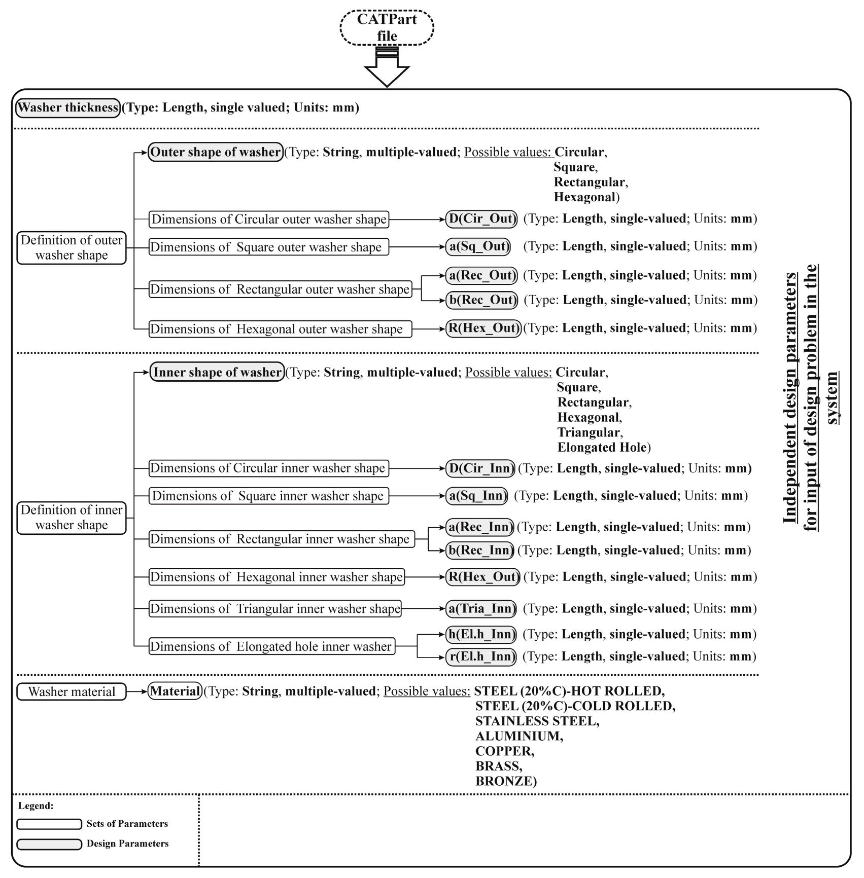
Cutting die-components’ design data can be expressed in terms of design entities called design parameters. The design parameters can be classified into two basic categories: the independent, or primary, and the dependent design parameters. The independent design parameters are responsible for a complete description of a washer’s form-features, and so they identify the outer-blanked washer shape, the inner-pierced washer shape, the outer and inner dimensions of the selected profiles, and the material’s thickness. The different values for independent design parameters represent the possibility for different washer variants (Fig. 1) and, in this manner, different design problems. Independent parameters must be created to enable user-direct input of the die-design problem within the system. Thus, during the first stage of developing the module GAJA1, it is necessary to establish a complete and systematic parametric database from the field of defining washers’ information regarding their shapes and dimensions. This has to be defined in such a way that will allow the system to use it for direct inferences regarding its effect within a certain design situation on the design implementation of the cutting die-components. The database was practically implemented using the functionality of the CATIA V5, which allowed for the creation of user-defined parameters, hence making it possible to organize the data on the washer in the form of a tree-structure. The user-defined parameters were thus used as an agent for recording and representing the shape and dimensional characteristics of the washer. When establishing the database it should be started from a one-washer variant and by using evident denominations of those user-defined parameters that have to be structurally-located within single logically-denominated sets of parameters for later programming, and an understandable interaction between the user and the system. Then the expected ranges of the die design-problems that the die-developing company envisages that will need to be performed in the future need to be specified. This was defined by the identification of parameters according to the values they can occupy (single- or multiple-valued). Two multiple-valued parameters of the type ‘string’ were created for varying the shape of the washer, and then the required values were prescribed. Combinations of potential values for the multiple-valued parameters defined within our database by regarding the washer’s form, allow for the defining of 24 different design problems, i.e., washer variants (four outer-shapes of the washer and six inner-shapes=24 different shape variants of a washer), where it is possible to upgrade or modify the existing database by additional values at any time. After visualizing a method of representing the dimensions of all the planned washer’s shape profiles, where 13 length-type parameters could be defined, the range for identifying the washer variants was considerably increased. Finally, a length-type parameter was created for presenting the thickness of the washer.
Fig. 3 shows the database for determining various washer variants, i.e, the numbers and names of the parameter sets, and the numbers, types, names, units, and pre-defined values of the design-parameters. The proposed database is universally-applicable for all types of simple-shaped sheet-metal stamping parts. Within its structure, only the number of those design parameters that determine the properties of a certain sheet-metal product can be increased or decreased. The composed database would also act as a user-interface for an efficient interaction between the user and the system. By using the user-interface, it would be possible to directly input a current compound cutting die-component’s design problem within the system. The major benefit of the database is that the parameters representing the shape and dimensions of the washer within it are specified in such a way that would enable the system to perform direct reasoning regarding the effects of their values when implementing the design of cutting die-components. Although the database currently integrates properties of simpler shape profiles, it can be upgraded at anytime with additional parameters identifying the properties of random, and also more complex shape profiles. When the overall system’s architecture is established, the ‘PWDB’ serves as a design problem input mask where the values of the contained (independent) design parameters can be set.
Fig.3 Database ‘PWDB’ for identifying some different washer configurations regarding their shapes, dimensions and materials
3.1.2. Establishment of the sub-module ‘ADSDW’ for automatically driving the shape and size of the washer
The composed database does not operate dynamically, as yet, which means that the values for those design-parameters engaged within it do not allow for the manipulation or modification of the CAD model’s geometrical features regarding the washer, as these do not currently exist. Upon establishing an appropriate parametric database, it is necessary to establish an adequate sub-module ADSDW, which would allow for flexible driving of the shape and size of the washer. This means that it is necessary to create suitable entities for presenting the shape and size of the washer, and for determining a methodology that would enable them to behave according to the parameter values within the database. One of the most important tasks is to define a methodology for flexibly modifying the shape of the washer’s contours. In this case, the shape contours of the washer have to be capable of self-adjustment to predetermined parameter values of ‘Outer shape of washer’ and ‘Inner shape of the washer’ within the database.
The methodology for establishing the sub-module ‘ADSDW’ includes the followings (Fig. 4).
Fig.4 Methodology for establishing the sub-module ‘ADSDW’
(a) The creation of geometrical sets for installing and classifying shape-sketches. Two geometrical sets have been created (Geometrical Set.1 and Geometrical Set.2) for the separate installations of outer and inner shape-sketches of the washer.
(b) The creation of shape-parameters that intended for the parametric driving of the product’s shape. Two curve-type parameters named ‘Outer stamped part shape’ and ‘Inner stamped part shape’ have been created and installed separately within Geometrical Set.1 and Geometrical Set.2, respectively.
(c) The creation of geometrical-sketches that correspond to the multiple-values of the parameters ‘Inner shape of washer’ and ‘Outer shape of washer’ inside the database. Four sketches were created for presenting the outer and six for the inner washer-shapes, respectively. Every sketch is located within an adequate geometrical set and has an appropriate denomination for a clear conception as to which parameter value a certain sketch belongs.
(d) Programming the behaviors of the curve-typed parameters ‘Outer stamped part shape’ and ‘Inner stamped part shape’ according to predetermined parameter values of ‘Outer shape of washer’ and ‘Inner shape of washer’ inside the database using ‘IF-THEN’ production rules. In this way, the shape-contours from which the washer’s features will be modeled, are parametrically driven (two rules parametrically drive the outer and inner shapes of the washer separately). An advanced parameterization method enables those created rules regarding the parameter values that define the shape of the washer in the database to be adjusted from an adequate sketch represented by the parameters ‘Outer stamped part shape’ and ‘Inner stamped part shape’—it activates the one that corresponds to the selected name, and deactivates those that do not correspond to the current denomination.
In order to achieve a comprehensive operation of the sub-module, it is finally necessary to create constraints in the form of dimensions and connect them to predetermined dimensional (length-type) parameters inside the database. Every profile has to be connected to an adequate parameter representing its dimension.
(e) Checking the correctness when operating the established sub-module ‘ADSDW’.
Sub-module ‘ADSDW’ represents a dynamically-driven skeleton that is able to adapt to the shape and dimension-identifying parameters within PWDB. In this way ADSDW is a unique basis for providing the automatic modeling of cutting die-components since it dynamically transforms the die design problem (values of independent design parameters) into the washer’s form-features, which will then be further used as a basis for the modeling and driving of the cutting die-components’ features.
3.1.3. Establishment of sub-module ‘RPFW’ for the reusing of parameters and features stored within the module GAJA1
Washer information stored within the database PWDB and the geometric features of the washer provided by the sub-module ADSDW are the basis for constructing and setting up those design constraints intended for operation within the last system’s module GAJA2, which will provide automatic modeling of the cutting die-components. This is why these elements have to be converted into a form that will enable their usage within this module. Here, it should be considered that these elements must retain a connection with their source, i.e., the database PWDB and sub-module ADSDW. Thus, the bi-directional-associative implementation of related changes must be provided. Changes to the elements in PWDB and ADSDW also have to be implemented within the module GAJA2 where they are used for providing its function. A publication mechanism that enables control over the created external references was used, in order to construct the sub-module RPFW within CATIA V5.
3.2. Methodology for the development of module GAJA2 for the automatic modeling of cutting die-components
Compound cutting die-components are directly responsible for performing the shaping (blanking and piercing) operations on a washer, and consequently include some geometrical features that correspond to its shape and dimensions. Thus, a basis for the development of module GAJA2 is the complete functioning of module GAJA1. Since shaping features can be directly modeled with the use of the curve-type parameters ‘Outer stamped part shape’ and ‘Inner stamped part shape’, the change is automatically performed through the CATIA replace-function option, which offers extraction of the piercing and blanking profiles of cutting features through ‘Tool for Synchronize’, straight from module GAJA1 (Fig. 5). To construct sub-module GAJA2, three separate part-files, namely GAJA2_Piercing-Punch, GAJA2_Compound, and GAJA2_Blanking-Matrix were created and placed inside GAJA.CATProduct.
Fig.5 Active replacement window informing a user that the rectangular shape of the piercing-feature will be replaced by a hexagonal one
Functional and procedural knowledge were used for modeling the feature-based models representing cutting die-components. Flexible design constraints were established for the identification, derivation, and calculation of the dependent design parameters by the use of independent parameters and geometrical features from the module GAJA1.
For each design problem, the design constraints must be capable of determining the values of each dependent design parameter that drives the behavior of a certain cutting die-component’s design feature. On this basis, the 3D CAD system can then automatically perform actions such as the calculations of dimensions, positions, and orientations regarding the cutting die-components’ 3D features. The constraints should also enable execution of more complex modeling operations such as the selection, activation or deactivation of 3D CAD features. Some considerations, when creating such knowledge-models of cutting die-components, are given below.
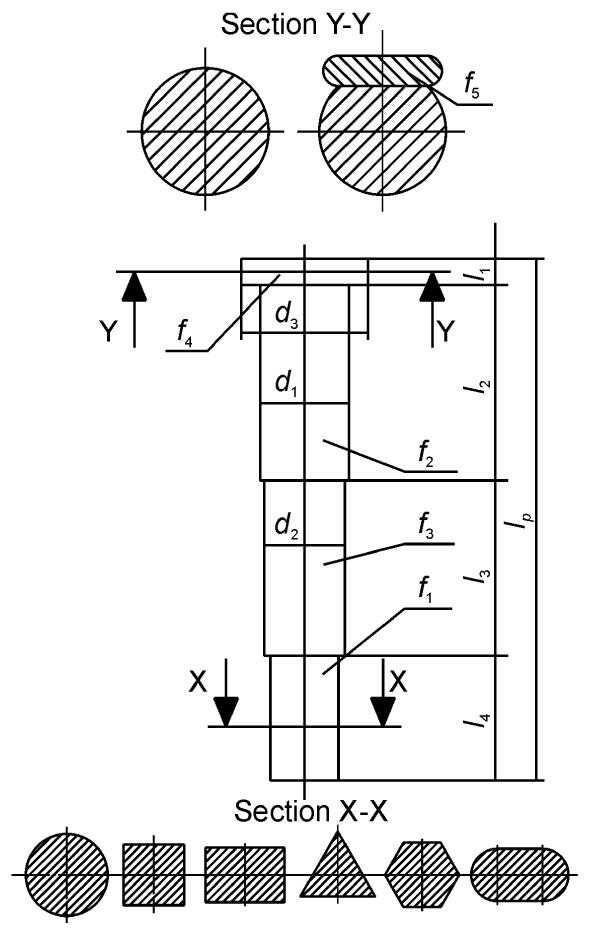
The piercing-punch is responsible for piercing the inner-washer hole and was modeled using four 3D pad-features that identify the perforating part (f1), the press-fit part (f2), the slip-fit part (f3), and the shoulder-part (f4) of the piercing-punch, respectively (Fig. 6). Feature f1, representing the perforating-area of the piercing-punch, was built with the use of an externally-published washer parameter ‘Inner stamped part shape’ that, through the functioning of sub-module ADSDW, allows for automatic shape-adoption whenever the shape of the washer’s pierced-hole within the PWDB is modified. Afterwards, when the length-type parameters for identifying the properties of other piercing-punch features were created, parameter d1 was used for identifying the press fit-diameter in the punch-plate within a rule that selects proper mathematical formulation regarding the currently-selected shape of the piercing-profile and its dimensions and automatically accomplishes a calculation of the d1 value. The parameters of the sketches used for the modeling-features consisting of slip-fit diameter d2 and shoulder-diameter d3 were then expressed by formulas that drive them in the forms of fixed mathematical-relations regarding parameter d1. All formulations for calculating the values of the parameters d1, d2 and d3 were derived according to the company’s manufacturing standards. These standards incorporate results of long-term testing of cutting-die components in a real production environment and the company’s best manufacturing practice. Additionally the multiple-valued parameter τs representing the shearing strength of possible washers’ materials was created and added to ‘PWDB’. Then a rule was employed to connect values of parameter τs with the values of the parameter ‘Material’. Using the sub-module RPFW parameter τs was transferred to module GAJA2 where it was further used as an argument within a rule, that automatically selects suitable punch material and its elastic modulus E. Using currently-selected values for parameters τs and E, the system calculates a proper value for the punch length lp in order to prevent buckling of the punch. Based on the currently-calculated value of parameter lp and using a rule, the system automatically prescribes values for parameters l1, l2, l3, l4 and l5 which represent the lengths of individual punch features. Values stored within the rule were determined with the use of the company’s manufacturing standards which were, in this case, updated with the results of finite element analyses.
Fig.6 Possible geometrical configurations for a shoulder piercing-punch
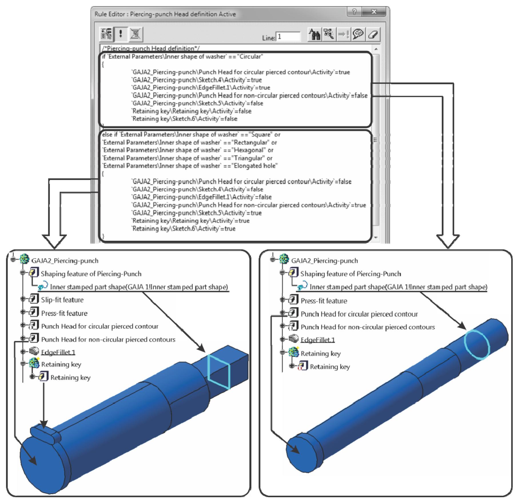
Later, according to the possible ranges of a washer’s inner-shaped holes, the piercing area of the punch was employed for the production of six different shapes and, in the case where this shape was not circular, the punch must be kept from turning. In order to provide this functionality, experts have proposed a method for securing a piercing-punch from turning, where a flat is machined in the punch head, and a round-end key (f5) is inserted. In this manner, the pad-features can be used for modeling an additional head-shape and round-end key. Then the feature selection algorithm was written into the Rule Editor, in order to activate a proper combination of features, and generate a solid CAD model of the piercing-punch based upon the requirement as to whether a securing of the piercing-punch is needed or not. ‘Inner shape of washer’ was used inside the rule as a driving parameter for the feature manipulation mentioned (Fig. 7).
Fig.7 Possible geometrical configurations for a shoulder piercing-punch
Modeling of the blanking-matrix was performed in the same manner as that of the piercing-punch, with the difference that the design decisions’ constraints were driven with the help of parameters ‘Outer shape of washer’ and the corresponding parameters representing the dimensions of possible outer-washer shape profiles from module GAJA1. These parameters were used to establish mathematical relations for calculating the size of parameter Dbm (Fig. 1). The proper selection of a formulation for calculating Dbm was performed using a rule regarding the current values of the parameters ‘Outer shape of washer’ and dimensional parameters D(Cir_Out), a(Sq_Out), a(Rec_Out), b(Rec_Out) and R(Hex_Out). Parameter values representing the rest of the blanking-matrix features’ properties were determined through the form of fixed relations according to parameter Dbm, which were established according to the company’s internal design and manufacturing standards. The blanking-opening was modeled with the help of the published parameter ‘Outer washer profile’ transferred from sub-module RPFW, using a pocket feature. The last rule is the driving activation and deactivation of an additional feature representing a dowel (Figs. 8b and 8c), which is required in the case of blanking a non-circular washer’s profile.
The published ‘Inner washer profile’ and ‘Outer washer profile’ parameters from module GAJA1, were used to construct the shaping features of the compound. Furthermore, those parameters identifying the size of the compound’s remaining geometrical features are driven by the rule that selects a proper formula for their calculation according to the currently-selected value of the parameter ‘Outer washer shape’, and the parameter identifying the size of the selected parameter. Another rule is activated for the additional feature representing the dowel, whenever one of the parameters values ‘Outer shape of washer’ or ‘Inner shape of washer’ is not ‘Circular’.
4. Evaluation and application of the system
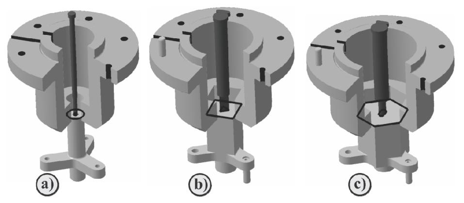
The system’s performance was tested by both experienced and inexperienced die-designers within Emo-orodjarna d.o.o, Slovenia, which is a development production company specializing in the planning, designing and making of high-quality cutting dies. The designers had to perform a design for cutting die-components responsible for forming three washer variants different in shapes, dimensions, and materials (Fig. 8) using the traditional approach, and then using the proposed system. Problems regarding the design cutting die-components were inputted in PWDB. Then ADSDW converted the problem’s identification parameters into the geometrical form of the corresponding forming profiles. RPFW then updated the parameters’ values and forming profiles within module GAJA1 and then transferred them into each knowledge-based template within module GAJA2. Within each template, the forming features of the cutting die-components were modeled first on the basis of the updated forming profiles (Fig. 8a). Then the system recognized the shapes of the forming profiles and selected a proper constraining formula for the calculations of features’ sizes (i.e., press fit feature) that are directly driven (dependent) by the properties of those profiles. After the system perceived the change in washer material, it automatically determined the lengths of the punch’s constitutive features in order to prevent the punch from buckling. These features were then modeled automatically. The system also used information about the shape of the forming profile to infer whether prevention from turning of the cutting die-elements must be provided. In the case that this condition must be satisfied, it automatically modeled addition features such as a round-end key and dowels (Figs. 8b and 8c). Finally the system used internal constraining formulas based on companies’ designs and manufacturing standards, and automatically modeled the properties of the rest of the cutting die-components’ features. Since the system developed by GAJA methodology represents an ‘intelligent’ assembly template, the above-described processes were performed in a single place after a new set of independent design parameters’ values were inputted, and the update function was applied.
Fig.8 Three automatically-generated configurations of cutting die-components by the functioning of the system
The results showed that by using the presented system the design time was reduced by 41% in comparison with the traditional processes performed by the experts, and by 74% in comparison with traditional processes performed by inexperienced die designers. The time-savings occurred on account of eliminating the repetitive reasoning processes of the die designers and the manual-transforming results of these activities in the form of 3D geometrical features. The design time-savings were even greater when more design problems needed to be resolved. Finally, the system’s results were evaluated by highly-experienced designers who concluded that the cutting die-components’ designs performed by the system were acceptable and that using this system provided excellent design quality. At the same time, this system presents an exceptional tool for the training of inexperienced designers, who can obtain greater insight into how design knowledge is applied during the designing of cutting die-components. The presented system performs the design of cutting die-components automatically, and significantly shortens the design-time, improves the design-quality, and enables training for inexperienced designers. The experimental results showed that this system saves up to an hour of design-time when multiple design-problems need to be solved.
5. Conclusions
This paper proposed a new methodology for establishing a parametric system for the automatic designing of cutting die-components, like piercing-punch, compound and blanking-matrix. The system developed by this methodology represents an intelligent assembly template which is composed of two modules GAJA1 and GAJA2. GAJA1 is responsible for the direct input of a die-design problem regarding the shape, dimensions, and material of a washer, its extraction in the form of geometrical features and the transferring of relevant design parameters and features to the module GAJA2. GAJA2 interprets the current values of the input parameters, and automatically performs a modeling process for cutting die-components using a company’s internal manufacturing and design standards. The proposed methodology allows for the establishment of a system that corresponds to the specific standards of die-developing companies and is affordable for small and medium-sized companies.
The system developed by this methodology has been implemented using the built-in modules Part Design, Assembly Design, and API of the commercial 3D CAD system CATIA V5, and its advanced publication mechanism and functional and procedural knowledge regarding the modeling of cutting die-components. The system’s architecture allows for the incorporation of specific standards regarding stamping companies. The system performs chaining through constraint space, solves design problems, and performs the modeling of cutting die-components automatically thus significantly shortening the design time, improves the design quality, and enables training for inexperienced designers. The experimental results showed that this system can save up to one hour of design time when multiple design-problems need to be solved. Further research work would be in the integration of a dependent geometrical design parameter identifying clearance between cutting die-elements. Since this parameter is strongly related to the tolerances and the quality of the cut wall, research effort will be focused on determining optimal values for blanking and piercing clearances, and their integration within the system. Later, this will enable complete functioning of the system.
[1] Bandini, S., Sartori, F., 2006. Industrial Mechanical Design: the IDS Case Study. Proceedings of Design Computing and Cognition. Springer-Verlag,Eindhoven, the Netherlands :141-160.
[2] Baxter, D., Gao, J., Case, K., Harding, J., Young, B., Cochrane, S., Dani, S., 2007. An engineering design knowledge reuse methodology using process modeling. Research in Engineering Design, 18(1):37-48.
[3] Bettig, B., Hoffmann, C.M., 2011. Geometric constraint solving in parametric computer-aided design. Journal of Computing and Information Science in Engineering, 11(2):021001
[4] Chin, K.S., Tang, D., 2002. Web-based concurrent stamping part and die development. Concurrent Engineering, 10(3):213-228.
[5] Choi, J.C., Kim, B.M., Cho, H.Y., Chul, K., 1998. A compact and practical CAD system for blanking or piercing of irregular-shaped sheet metal products and stator and rotor parts. International Journal of Machine Tools and Manufacture, 38(8):931-963.
[6] Jia, Z.X., Li, H.L., Zhang, X.C., Li, J.Q., Chen, B.J., 2011. Computer-aided structural design of punches and dies for progressive die based on functional component. The International Journal of Advanced Manufacturing Technology, 54(9-12):837-852.
[7] Kim, J., Pratt, M.J., Iyer, R.G., Sriram, R.D., 2008. Standardized data exchange of CAD models with design intent. Computer-Aided Design, 40(7):760-777.
[8] Kim, Y., Kim, L., Jun, C., 2006. Parametric design of a part with free-form surfaces. Journal of Zhejiang University SCIENCE A, 7(9):1530-1534.
[9] Kumar, S., Singh, R., 2011. An automated design system for progressive die. Expert Systems with Applications, 38(4):4482-4489.
[10] Kumar, S., Sight, R., Sekhon, G.S., 2008. An Expert System for Design of Blanking Dies for Sheet Metal Operations. , Proceedings of the World Congress on Engineering and Computer Science (WCECS), San Francisco, USA, :
[11] Lin, B.T., Hsu, S.H., 2008. Automated design system for drawing dies. Expert Systems with Applications, 34(3):1586-1598.
[12] Lin, B.T., Chan, C.K., Wang, J.C., 2008. A knowledge-based parametric design system for drawing dies. The International Journal of Advanced Manufacturing Technology, 36(7-8):671-680.
[13] Lin, B.T., Chang, M.R., Huang, H.L., Liu, C.Y., 2009. Computer-aided structural design of drawing dies for stamping processes based on functional features. The International Journal of Advanced Manufacturing Technology, 42(11-12):1140-1152.
[14] Liu, Z.J., Li, J.J., Wang, Y.L., Li, C.Y., Xiao, X.Z., 2004. Automatically extracting sheet-metal features from solid model. Journal of Zhejiang University-SCIENCE, 5(11):1456-1465.
[15] McMahon, C., Browne, J., 1999. CADCAM: Principles, Practice and Manufacturing Management. Addison-Wesley,Massachusetts :
[16] Mok, C.K., Chin, K.S., Ho, J.K.L., 2001. An interactive knowledge-based CAD system for mould design in injection moulding processes. The International Journal of Advanced Manufacturing Technology, 17(1):27-38.
[17] Potocnik, D., Ulbin, M., Dolsak, B., 2012. Knowledge-based system for supporting the design of a plate-press. Journal of Computing and Information Science in Engineering, 12(2):024502
[18] Saridakis, K.M., Dentsoras, A.J., 2005. Evolutionary Neuro-Fuzzy Modeling of Parametric Design. , I*PROMS 1st Virtual International Conference on Intelligent Production Machines and Systems, 315-320. :315-320.
[19] Schilling, A., Kim, S., Weimann, D., Tang, Z., Choi, S., 2006. CAD-VR geometry and meta data synchronization for design review applications. Journal of Zhejiang Universit-SCIENCE A, 7(9):1482-1491.
[20] Shah, J.J., Mntyl, M., 1995. Parametric and Feature-Based CAD/CAM: Concepts, Techniques, and Applications. John Wiley & Sons, Inc.,New York :
[21] Stroud, I., Nagy, H., 2011. Solid Modelling and CAD Systems. Springer-Verlag,London Ltd :
[22] Tang, D., Eversheim, W., Schuh, G., Chin, K.S., 2003. Concurrent metal stamping part and die development system. Proceedings of the Institution of Mechanical Engineers, Part B: Journal of Engineering Manufacture, 217(6):805-825.
[23] Tay, F.E.H., Gu, J., 2002. Product modeling for conceptual design support. Computers in Industry, 48(2):143-155.
[24] Tor, S.B., Britton, G.A., Zhang, W.Y., 2003. Indexing & retrieval in metal stamping die design using case based reasoning. Journal of Computing and Information Science in Engineering, 3(4):353-362.
Open peer comments: Debate/Discuss/Question/Opinion


Open peer comments: Debate/Discuss/Question/Opinion
<1>