Affiliation(s):
1.
Institute of Refrigeration and Cryogenics, Zhejiang University, Hangzhou 310027, China; moreAffiliation(s): 1.
Institute of Refrigeration and Cryogenics, Zhejiang University, Hangzhou 310027, China; 2.
School of Information and Electrical Engineering, Zhejiang University City College, Hangzhou 310015, China; less
Xue-jun Zhang, Ke-qing Zheng, Ling-shi Wang, Wei Wang, Min Jiang, Sheng-ying Zhao. Analysis of ice slurry production by direct contact heat transfer of air and water solution[J]. Journal of Zhejiang University Science A, 2013, 14(8): 583-588.
@article{title="Analysis of ice slurry production by direct contact heat transfer of air and water solution", author="Xue-jun Zhang, Ke-qing Zheng, Ling-shi Wang, Wei Wang, Min Jiang, Sheng-ying Zhao", journal="Journal of Zhejiang University Science A", volume="14", number="8", pages="583-588", year="2013", publisher="Zhejiang University Press & Springer", doi="10.1631/jzus.A1300171" }
%0 Journal Article %T Analysis of ice slurry production by direct contact heat transfer of air and water solution %A Xue-jun Zhang %A Ke-qing Zheng %A Ling-shi Wang %A Wei Wang %A Min Jiang %A Sheng-ying Zhao %J Journal of Zhejiang University SCIENCE A %V 14 %N 8 %P 583-588 %@ 1673-565X %D 2013 %I Zhejiang University Press & Springer %DOI 10.1631/jzus.A1300171
TY - JOUR T1 - Analysis of ice slurry production by direct contact heat transfer of air and water solution A1 - Xue-jun Zhang A1 - Ke-qing Zheng A1 - Ling-shi Wang A1 - Wei Wang A1 - Min Jiang A1 - Sheng-ying Zhao J0 - Journal of Zhejiang University Science A VL - 14 IS - 8 SP - 583 EP - 588 %@ 1673-565X Y1 - 2013 PB - Zhejiang University Press & Springer ER - DOI - 10.1631/jzus.A1300171
Abstract: In this paper, a novel system using direct contact heat transfer between air and water solution was proposed to generate ice slurry. The heat transfer process and the system performance were studied; energy efficiency coefficients of 0.038, 0.053, and 0.064 were obtained using different solutions. An empirical relationship between the volumetric heat transfer coefficientUv and the main parameters was obtained by fitting the experimental data. The Uv calculated from the empirical formula agreed with the experimental Uv quite well with a relative error of less than 15%. Based on the empirical formula, a laboratory-scale direct contactice slurrygenerator was then constructed, with practical application in mind. If the air flow rate is fixed at 200 m3/h, the ice production rate will be 0.091 kg/min. The experimental results also showed that the cold energy consumption of the air compressor accounted for more than half of the total amount. To improve the system energy efficiency coefficient, it is necessary to increase the air pipes insulation and the solution’s thermal capacity, and also it is appropriate to utilize the free cold energy of liquefied natural gas (LNG).
Darkslateblue:Affiliate; Royal Blue:Author; Turquoise:Article
Article Content
1. Introduction
Ice slurry is a mixture of liquid and ice crystals with diameters from 5 μm to 1 cm. In general, the liquid solution is a binary solution consisting of water and a freezing point depressant, such as ethylene glycol (EG), ethanol, and chloride. Due to its particular composition, ice slurry has excellent features including high cool-storage capacity, fast cool-release rate, and good fluidity. Moreover, it can be transported by pumps (Kalaiselvam et al., 2009). Therefore, ice slurry is a promising second refrigerant in various cooling processes, such as chemical, fishery and food industries (Tassou et al., 2010), central air-conditioning systems, and thermal energy storage systems (Wang and Kusumoto, 2001).
There are several methods of making ice slurry, such as the vacuum method, the fluidized bed method, the scrape method, the super-cooling method and the direct contact method. All methods have their own advantages as well as strict requirements and limitations in practical application (Kauffeld et al., 2010). A high level of airproofing and vacuumization is required for the vacuum method (Kim et al., 2001). High precision control of the surface temperature, the flow rate, and the solid particle size are required for the fluidized bed method (Meewisse and Ferreira, 2003). For the scrape method, the system where the scrape part is easily damaged is complex and of low energy efficiency (Chibana et al., 2002). Due to the unstable super-cooling state, a low ice content and poor stability are found in the super-cooling method. In the conventional direct contact ice slurry making system, the low temperature two-phase refrigerant (i.e., the dispersed phase) with a low temperature is injected from the nozzle into water (i.e., the con-tinuous phase). The refrigerant exchanges heat with the water by direct contact. The water temperature decreases till the ice crystals appear, while the refrigerant gets warmer and warmer till it vaporizes and flows out of the generator. However, in this system, some problems still exist, such as the large refrigerant consumption, the difficulty in separating the refrigerant from the water, and the ice blockage in the nozzle. To overcome the above weaknesses, Thongwik et al. (2008) used carbon dioxide as the dispersed phase, instead of the two-phase refrigerant. In their study, carbon dioxide was cooled and then injected into the water solution to make ice slurry. The effects of the mass flow rate, the inlet temperature of the dispersed phase, and the height of the continuous phase on the volumetric heat transfer coefficient (Uv) were also experimentally studied.
Although much research has been carried out on direct contact heat transfer, work on the heat transfer process between cold gas and a water solution involving phase transition and ice slurry generation in the continuous phase, was only found in (Thongwik et al., 2008). Zhang et al. (2008; 2010a; 2010b) and Zheng et al. (2010) studied the effects of the mass flow rate, the nozzle diameter, and the gas inlet velocity on the volumetric heat transfer coefficient (Uv), and found that the addition of ethylene glycol (EG) could prevent the ice blockage in the nozzle effectively.
In this paper, a direct contact heat transfer ice slurry making system was proposed, in which carbon dioxide is replaced by air as the dispersed phase, and a dimensionless relationship between the easily measured main factors and Uv was obtained by fitting the experimental data. Then based on this empirical formula, a laboratory-scale direct contact ice slurry generator was constructed, with a view to practical application.
2. Heat transfer regression
To study the direct contact heat transfer process between the air and the water solution, a direct contact heat transfer system was first fabricated. As shown in Fig. 1, the air flows following the arrow points. In the first direct contact heat exchanger, pressurized by the air compressor, air is pumped into the antifreeze solution which is cooled by the thermostatic bath (measuring range: −20–100 °C; fluctuation range: ±0.05 °C), and it is also dehumidified there to prevent the ice blockage in the subsequent pipes and nozzle, which is located at the bottom of the ice slurry generator; in the second direct contact heat exchanger (i.e., the generator), the air is injected from the nozzles at the spindle of the generator into the EG aqueous solution to make ice slurry.
Fig.1 Schematic diagram of the direct contact system
The generator consists of two synthetic glass tubes and a vacuumized interlayer between them for thermal insulation. Seven calibrated thermocouples (measurement accuracy: ±0.2 oC), denoted by T1 to T7, are fixed on the inner wall of the generator, as well as the pipes. The data logger is 34970A manufactured by the Agilent Technologies.
In one series of experiments, the temperature changes for both 5% and 10% EG aqueous solutions are shown in Fig. 2.
Fig.2 Solution temperature change with time
Volumetric heat transfer coefficient Uv is a coefficient commonly used in the field of chemical engineering to evaluate total heat transfer performance in a specific volume. It is the most important parameter to assess the performance of the ice slurry generator, and can be calculated by
,
where Q is the heat transfer rate between the air bubbles and the water solution, V is the water solution volume, Tw is the water solution temperature, and Tg,i is the gas temperature at the generator inlet.
In the heat transfer process between the air bubbles and the water solution, the main factors that affect Uv can be summarized as follows: the gas inlet velocity ui, the gas density ρg, the liquid physical properties (constant pressure specific heat capacity cp, thermal conductivity λ, liquid density ρl, viscosity υ, and surface tension σ), the nozzle diameter dn, the solution column height H, and the generator diameter D. Thus, Uv can be expressed as
.
For nondimensionalization, Eq. (2) is hence converted to Eq. (3),
.
To simplify further, the last three items of Eq. (3) are combined to represent the solution’s Reynolds number (Re) and Prandtl number (Pr), as Eq. (4) expressed, where ui is regarded as the relative velocity of the solution to the gas.
.
Finally, the following dimensionless Eq. (5) is used to fit the experimental data.
,
where a, b, c, d, and e are the pending coefficients; the first item on the right side is the ratio of the density of the air to the solution; the second item represents the structural parameters of the generator; and the last two items are Reynolds number and Prandtl number, respectively.
By measuring the air inlet and outlet temperatures, the water temperature, and the air mass flow rate, the volumetric heat transfer coefficient Uv can be calculated by Eq. (1). Then the pending coefficients a, b, c, d, and e in Eq. (5) are obtained by nonlinear least squares regressions, as shown in Eq. (6).
.
By moving the D- and λ-term from the left side to the right side, Eq. (6) can be arranged as
.
To check the validity of Eq. (7), under the same experimental conditions, the volumetric heat transfer coefficient (Uv) is calculated by Eq. (7), and plotted in Fig. 3. It is found that the calculation values agree well with the experimental results, and the maximum relative error is less than 15%. Therefore, Eq. (7) is used to design the direct contact ice slurry generator.
Fig.3 Correlation results of volumetric heat transfer coefficient
3. Prototype
Aimed at practical application, a laboratory-scale ice slurry making system was constructed to study the ice formation process (Fig. 4). With the first direct contact heat transfer, air is pumped by an air compressor into the 35% EG solution cooled by a refrigeration system, and then injected from the nozzles at the spindle of the ice slurry generator into the 10% EG aqueous solution to make ice slurry with the second direct contact heat transfer. Air is exhausted from the top of the ice slurry generator, and re-enters the air compressor inlet to start the next cycle.
Due to the enlarged heat transfer area contacted by air bubbles and a Stirring effect encouraged also by air bubbles, the heat transfer coefficient between air and solution is improved.
Fig.4 Prototype of ice slurry making system
4. Results and discussion
4.1. Cold energy consumption
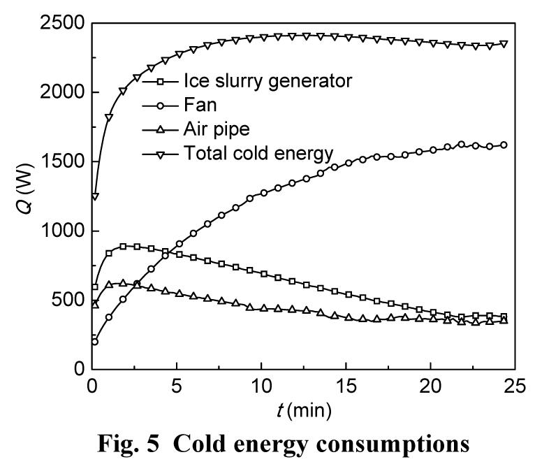
In the air cycle, the total cold energy obtained by air from the first heat exchanger is consumed by the following three parts along the way: the air pipes, the ice slurry generator, and the air compressor. Fig. 5 shows the cold energy consumption of the ice slurry generator and the air pipes decreases after reaching the maximum values of 890 W and 620 W, respectively, while the cold energy consumption of the air compressor increases continuously until reaching the maximum value of 1620 W. The total cold energy increases from 1254 W at the beginning to 2411 W about 12 min later, and is almost unchanged subsequently.
Fig.5 Cold energy consumptions
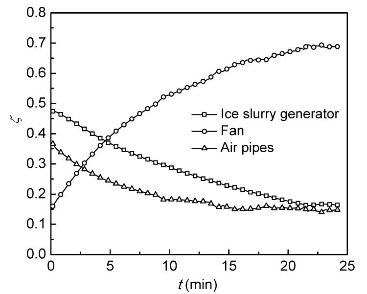
Also from Fig. 6, it can be seen that the cold energy consumption proportions ζ of both the ice slurry generator and the air pipes decrease with time, while that of the air compressor increases with time. When the operation is stable, the proportion of the air compressor rises to 65%, while that of the ice slurry generator drops to 20%. Thus, in order to improve the cold energy consumption proportion of the ice slurry generator, the air pipes insulation should be further improved, and the heat elimination of the air compressor should be enhanced.
Fig.6 Proportions of the cold energy consumption
4.2. Energy efficiency coefficient
The electric energy consumption of the air compressor and the refrigeration system is measured by an electric meter, and recorded every 5 min.
For the heat transfer rate Q between the air bubbles and the water solution in Eq. (1), if the heat leakage to the surroundings is not neglected, then
,
where G is the air mass flow rate; cp is the air specific heat capacity; Tg,o is the gas temperatures at the outlet of the ice slurry generator; and Q1 is the heat leakage. In this experiment, the heat leakage of the ice slurry generator is measured at about 20 W.
The energy efficiency coefficient η is defined as follows:
,
where P is the refrigerating output of the system, Pac is the input power of the air compressor, and Pr is the input power of the refrigerator.
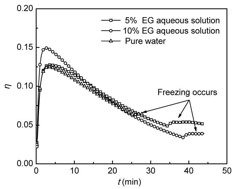
Fig. 7 shows the system energy efficiency coefficients under different concentrations of ice making solutions: 5% EG aqueous solution, 10% EG aqueous solution, and pure water. In the initial 12 min, the 10% EG aqueous solution system has a higher η than others. The total input power of the air compressor and the refrigeration system in the process of both the cooling down and the ice slurry production is almost constant at 5400 W. After reaching the maximum value in the beginning period, the energy efficiency coefficient decreases along with time, and remains unchanged after the solution reaches the freezing point. In the beginning period, a larger temperature difference exists between the cold air and the solution in the ice slurry generator, which causes the solution to get cold more easily. With the decreasing of the solution temperature in the ice slurry generator, the temperature difference between the solution and the cold air reduces, and the heat transfer rate slows down. Once the solution freezes, the cold energy input contributes to phase change, thus the solution temperature remains constant, and the energy efficiency coefficient also remains fixed.
Fig.7 System energy efficiency coefficients
Also as shown in Fig. 7, the system energy efficiency coefficients are low, not more than 0.15. The energy efficiency coefficient is calculated as 0.038 for 10% EG aqueous solution. For 5% EG aqueous solution and pure water, the energy efficiency coefficients are 0.053 and 0.064, respectively. There are two rea-sons. One is that the evaporation temperature of the refrigerator is set at a low level of −13 °C. If the cold energy is supplied by liquefied natural gas (LNG) from the regasification facility rather than the refrigerator, there is no doubt that the system energy efficiency coefficient will be higher (Rocca, 2010). Another reason is that the solution does not have enough volume (i.e., thermal capacity) to absorb heat from the cold air. If the ice slurry generator diameter D is fixed, with the increase in the solution height H, the solution volume V increases, but the volumetric heat transfer coefficient Uv decreases, as shown in Eq. (1); furthermore, a higher pressure head of the air compressor is required for the air transportation. Thus, an appropriate solution height H can achieve a good trade-off between the solution thermal capacity and the energy consumption for the air transportation.
4.3. Ice production rate
Fig. 8 shows the ice slurry formation in the generator, where 10% EG aqueous solution was used as the ice making solution.
Fig.8 Ice slurry formation around the nozzles
The ice production rate is calculated as follows:
,
where m is the ice mass, and L is the latent heat of ice.
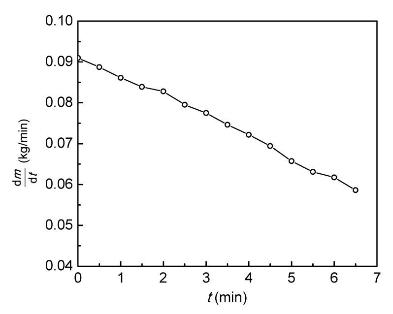
Fig. 9 shows the ice production rates in 10% EG solution after reaching the freezing point. It can be seen that the initial ice production rate is 0.091 kg/min when the air flow rate is 200 m3/h. The decline in the ice production rate is attributed to the decrease in the air flow rate caused by the ice blockage.
Fig.9 Ice production rate in 10% EG solution
5. Conclusions
Based on the empirical formula of heat transfer, a laboratory-scale direct contact ice slurry generator was constructed, and energy efficiency coefficients of 0.038, 0.053, and 0.064 were obtained using different solutions. Regarding practical applications, a direct contact ice slurry generator using air as the cooling fluid is feasible, especially applied to LNG cold energy. In the air cycle, the cold energy consumption of the air compressor accounts for more than half of the total amount, which is to be reduced. In order to improve the system energy efficiency coefficient, it is necessary to increase the air pipes insulation and the solution thermal capacity, and it is also appropriate to utilize the free cold energy of LNG.
[1] Chibana, K., Kang, C., Okada, M., Matsumoto, K., Kawagoe, T., 2002. Continuous formation of slurry ice by cooling water-oil emulsion in a tube. International Journal of Refrigeration, 25:259-266.
[2] Kalaiselvam, S., Karthik, P., Prakash, S.R., 2009. Numerical investigation of heat transfer and pressure drop characteristics of tube-fin heat exchangers in ice slurry HVAC system. Applied Thermal Engineering, 29(8-9):1831-1839.
[3] Kauffeld, M., Wang, M.J., Goldstein, V., Kasza, K.E., 2010. Ice slurry applications. International Journal of Refrigeration, 33(8):1491-1505.
[4] Kim, B.S., Shin, H.T., Lee, Y.P., Jurng, J., 2001. Study on ice slurry production by water spray. International Journal of Refrigeration, 24:176-184.
[5] Meewisse, J.W., Ferreira, C.A.I., 2003. Validation of the use of heat transfer models in liquid/solid fluidized beds for ice slurry generation. International Journal of Heat and Mass Transfer, 46(19):3683-3695.
[6] Rocca, V.L., 2010. Cold recovery during regasification of LNG part one: Cold utilization far from the regasification facility. Energy, 35(5):2049-2058.
[7] Tassou, S.A., Lewis, J.S., Ge, Y.T., Hadawey, A., Chaer, I., 2010. A review of emerging technologies for food refrigeration applications. Applied Thermal Engineering, 30(4):263-276.
[8] Thongwik, S., Vorayos, N., Kiatsiriroat, T., Nuntaphan, A., 2008. Thermal analysis of slurry ice production system using direct contact heat transfer of carbon dioxide and water mixture. International Communications in Heat and Mass Transfer, 35:756-761.
[9] Wang, M.J., Kusumoto, N., 2001. Ice slurry based thermal storage in multifunctional buildings. Heat and Mass Transfer, 37:597-604.
[10] Zhang, X.J., Qiu, L.M., Zhang, P., Liu, L., Gan, Z.H., 2008. Performance improvement of vertical ice slurry generator by using bubbling device. Energy Conversion and Management, 49:83-88.
[11] Zhang, X.J., Tian, X.J., Zheng, K.Q., Qiu, L.M., 2010. Research on the ice slurry generator using the direct contact heat transfer of gas and water solution. Journal of Engineering Thermophysics, (in Chinese),31(12):1997-2000.
[12] Zhang, X.J., Wu, P., Qiu, L.M., Zhang, X.B., Tian, X.J., 2010. Analysis of the nucleation of nanofluids in the ice formation process. Energy Conversion and Management, 51(1):130-134.
[13] Zheng, K.Q., Zhang, X.J., Tian, X.J., Qiu, L.M., 2010. Heat transfer performance of a single air bubble in direct contact ice slurry generator. CIESC Journal, (in Chinese),61(S2):58-61.
Open peer comments: Debate/Discuss/Question/Opinion


Open peer comments: Debate/Discuss/Question/Opinion
<1>