Affiliation(s):
1.
Department of Civil Engineering, Tsinghua University, Beijing 100084, China; moreAffiliation(s): 1.
Department of Civil Engineering, Tsinghua University, Beijing 100084, China; 2.
Research Institute of Highway of China Ministry of Transport, Beijing 100088, China; 3.
Institute of Chemical Machinery, Zhejiang University, Hangzhou 310027, China; less
Hui Liu, Ming-hua He, Yu-qi Luan, Jia Guo, Lu-lu Liu. A modified constitutive model for FRP confined concrete in circular sections and its implementation with OpenSees programming[J]. Journal of Zhejiang University Science A, 2013, 14(12): 856-866.
@article{title="A modified constitutive model for FRP confined concrete in circular sections and its implementation with OpenSees programming", author="Hui Liu, Ming-hua He, Yu-qi Luan, Jia Guo, Lu-lu Liu", journal="Journal of Zhejiang University Science A", volume="14", number="12", pages="856-866", year="2013", publisher="Zhejiang University Press & Springer", doi="10.1631/jzus.A1300185" }
%0 Journal Article %T A modified constitutive model for FRP confined concrete in circular sections and its implementation with OpenSees programming %A Hui Liu %A Ming-hua He %A Yu-qi Luan %A Jia Guo %A Lu-lu Liu %J Journal of Zhejiang University SCIENCE A %V 14 %N 12 %P 856-866 %@ 1673-565X %D 2013 %I Zhejiang University Press & Springer %DOI 10.1631/jzus.A1300185
TY - JOUR T1 - A modified constitutive model for FRP confined concrete in circular sections and its implementation with OpenSees programming A1 - Hui Liu A1 - Ming-hua He A1 - Yu-qi Luan A1 - Jia Guo A1 - Lu-lu Liu J0 - Journal of Zhejiang University Science A VL - 14 IS - 12 SP - 856 EP - 866 %@ 1673-565X Y1 - 2013 PB - Zhejiang University Press & Springer ER - DOI - 10.1631/jzus.A1300185
Abstract: openSees is a well-recognized open source platform with high compatibility, and it has a well-developed fiber element method to cope with nonlinear structural analysis. Fiber reinforced polymer (FRP) confined concrete can effectively improve the seismic performance of concrete structures. However, sophisticated constitutive models for FRP confined concrete are not available in the current version of openSees. In this paper, after reviewing several typical FRP confined concreteconstitutive models, a modified constitutive model for FRP confined concrete in circular sections was proposed based on Lam and Teng (2003)’s model with four main modifications including the determination of FRP rupture strain, ultimate condition, envelope shape, and hysteretic rules. To embed the proposed constitutive model into openSees is a practical solution for engineering simulation. Hence, the secondary development of openSees New UserMat was briefly demonstrated and a set of critical steps were depicted in a flow chart. Finally, with the numerical implementations of a series of FRP confined concrete members covering a wide range of load cases, FRP confinement types and geometric properties, the utility and accuracy of the proposed model compared with Lam and Teng (2003)’s model and new material secondary development in openSees were well validated.
Darkslateblue:Affiliate; Royal Blue:Author; Turquoise:Article
Article Content
1. Introduction
Lateral confinement of concrete enhances its strength and ductility significantly. By utilizing steel or fiber reinforced polymer (FRP) as confinement material, confined concrete has a higher strength and deformation capacity compared with unconfined concrete due to the tri-axial compressive status with respect to lateral confining. As a result, confined concrete has been increasingly applied in civil engineering, especially in seismic design (Park et al., 1982; Mander et al., 1988a; Shams and Saadeghvaziri, 1997). As a promising option for engineering applications, FRP have been widely introduced into the application of confined concrete, and its confinement can greatly enhance the compressive strength and ultimate strain of concrete at the same time (Samaan et al., 1998; Toutanji, 1999).
In early studies of confined concrete, the uniaxial constitutive models for steel confined concrete and FRP confined concrete were the same. However, a number of research groups showed that significant differences exist between FRP confined and steel confined concrete and that its direct use is inappropriate. This is because in most steel confined concrete models (Mander et al., 1988b), a constant confining pressure is assumed, which is the case of steel confined concrete when the steel is in plastic flow, but not the case for FRP confined concrete. As FRP composites tend to remain linearly elastic until final rupture, the lateral confining pressure in FRP confined concrete increases continuously with the increasingly hoop enlarging.
Considerable progress has been achieved in developing a constitutive model for describing FRP confined concrete over the last three decades. All these stress strain models can be classified into two categories: (a) design-oriented models, and (b) analysis-oriented models. Even though the analysis-oriented models have advantages in describing detailed mechanical behavior with the inevitable complexity of the incremental process, the design-oriented models can be much more effectively and practically used in engineering design. According to a comprehensive review and assessment of the FRP confined concrete constitutive models including design-oriented and analysis-oriented ones (Ozbakkaloglu et al., 2013), the design-oriented models generally performed better in predicting the ultimate strength and strain enhancement ratios. Among several typical design-oriented constitutive models listed in Table 1, the one proposed by Lam and Teng (2003) is simple and accurate in depicting the strength and ductility of FRP confined concrete members, and therefore playing an important role in their structural analysis and design). In consistence with the assessment result calibrated by 730 FRP confined concrete cylinders test database, Lam and Teng (2003)’s model is one of the top performing models (Ozbakkaloglu et al., 2013). He et al. (2013) modified Lam and Teng (2003)’s model slightly for analyzing FRP piers or columns. In this paper, the modified constitutive model, in which the ambiguity on selecting parameters empirically has been reduced, is more comprehensive and much better results are expected.
Table 1
Typical design oriented constitutive models for FPR confined concrete
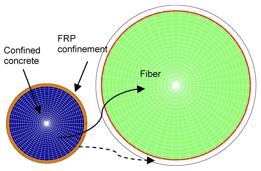
The fiber element method, which makes the structural modeling process more concise and efficient than the traditional finite element method, can be regarded as a distributed beam-system finite element method, i.e., the fiber element model is set up on the basis of a beam-system structural mechanics and uniaxial constitutive model of materials. In the fiber section, the assumptions that each fiber possesses its unique uniaxial constitutive material property, and no relative slippage exists between different fibers have been straightforwardly carried out. Spacone et al. (1996) and Monti and Spacone (2000) demonstrated the utility of the fiber element method in dealing with structural nonlinear analysis, and showed that the efficiency raised by the decrease of computational degree of freedom (DOF) and the accuracy of analysis can be successfully achieved at the same time. The schematic depiction of the fiber section of FRP confined concrete is shown in Fig. 1.
Fig.1 Schematic depiction of fiber section of FRP confined concrete members
OpenSees is an open framework with high compatibility and extendibility originally developed at University of California, Berkeley and currently supported by the American Pacific Earthquake Engineering Research Center (PEER) and an ever growing community. It has been utilized by the PEER based on object oriented C++ language source code since 1997. The OpenSees platform has embedded a fiber element method into its framework since it was first launched. Therefore, the nonlinear structural analysis based on the fiber element method can be completely conducted in OpenSees software mainly through a nonlinear beam column model and plastic hinge model. Since its utility and accuracy have been well verified, widespread acceptance and broad application of OpenSees have been achieved in the earthquake engineering research field.
The characteristics of the fiber element method are consistent with the idea of the design-oriented constitutive model; however, there is still no FRP confined concrete constitutive model embedded in the OpenSees platform up to now. For this reason, a modified constitutive model for FRP confined concrete based on Lam and Teng (2003)’s model is proposed in this paper and seamlessly embedded into OpenSees through UserMat secondary development to further broaden its application in structural analysis in combination with the efficient fiber element method.
2. A modified FRP confined concrete model
The constitutive model proposed by Lam and Teng (2003) is a promising and prevalent design-oriented model which combines a modified Hognestad (1951)’s parabola as the first branch. The envelope curve and its expressions are shown below and depicted in Fig. 2:
where σc and εc are the axial stress and axial strain of unconfined concrete, respectively; f0 is the intercept of the stress axis by the linear second branch; εt is the transition strain; εcu is the ultimate strain of the FRP confined concrete; Ec is Young’s Modulus of concrete; and E2 is the slope of the linear second portion.
Fig.2 Envelope curve and hysteretic rule of proposed FRP confined concrete Eu is the unloading modulus, and , , are ending points during unloading
In previous studies, some codes like BS 8110 (1997) and some research like Miyauchi et al. (1999) used Hognestad (1951)’s parabola to describe the ascending branch of the constitutive model, which is given by
,
where fc0* is the compressive strength of unconfined concrete. However, the model above cannot mirror the process of gradual development of FRP confinement. Therefore, a modified parabola should be able to reflect the development of the confinement effect with axial strain increase as given in Eq. (1). As to the linear second branch, the use of slope and intercept with the stress axis proposed by Samaan et al. (1998) was adopted in Lam and Teng (2003)’s model. Compared to existing test results, this approximation has been verified to offer a rational and concise approach as shown in Eq. (1). The parabolic first branch transits to the linear second branch smoothly at transition strain εt, which is given as
,
and
,
where is the compressive strength of the FRP confined concrete.
Based on the general shape of stress-strain curve described above, the determination of three parameters including ultimate strength fcc′, ultimate strain εcu, and intercept stress f0 is critical to constitutive model. In Lam and Teng (2003)’s model, it is suggested that the intercept stress f0 be equal to the compressive strength of unconfined concrete fc0* (f0=fc0*) for simplicity. As to the ultimate condition of FRP confined concrete, it is directly related to the ultimate transverse tension of FRP material which accordingly provides the maximum confining pressure on confined concrete. The actual maximum confining pressure fl,a is assumed to be controlled by the FRP rupture strain εh,rup instead of the ultimate strain εFRP achieved in tensile coupon test, and it usually can be much smaller than the ideal maximum confining pressure fl. In this way, a so-called FRP strain reduction factor kε was defined to describe the ratio between εrup and εFRP, i.e.,
.
Then, the actual confining pressure at ultimate condition fl,a can be calculated by
,
where D is the diameter, EFRP is the Young’s modulus of FRP, and tFRP is the thickness of FRP layer.
However, several deficiencies still remain when using this FRP confined concrete constitutive model in practical applications. Four major modifications have been proposed to further make Lam and Teng (2003)’s model more generally practical and accurate, which are given below.
1. FRP strain reduction factor kε is essential to the shape of the model; however, the specific value suggested in Lam and Teng (2003)’s model for different types of FRP confinement is not general and accurate enough. It is suggested that it should be determined by the unconfined concrete strength fc0* and elastic modulus of FRP fibers EFRP for each practical case.
Ozbakkaloglu and Akin (2012) reported that an increase of unconfined concrete strength results in a decrease of FRP rupture strain εh,rup, and an increase in elastic modulus of FRP EFRP also has an adverse influence in εh,rup. Based on the multivariable regression analysis covering 976 FRP confined specimens during the last two decades (Lim and Ozbakkaloglu, 2013), the expression of FRP rupture strain can be statistically quantified as
,
where 105 MPa≤Ef≤6.4×10⁵ MPa.
The expression above is able to predict the FRP strain reduction factor kε with an unconfined concrete strength up to 120 MPa, and confined by any FRP types of carbon FRP (CFRP), aramid FRP (AFRP), and glass FRP (GFRP). With this modification, the accurate approximation of actual ultimate confining pressure fl,a for each specific case can be achieved.
2. Lam and Teng (2003)’s model was proposed based on a database that mostly consists of FRP confined normal-strength concrete (90% of specimens’ concrete strength is less than 43 MPa).
In Lam and Teng (2003)’s model, the ultimate stress and ultimate strain were calculated by
,
.
However, with the increase of unconfined concrete strength fc0*, the normalized ultimate coefficients of stress and strain should be modified instead of being specified as 1 and 1.75, respectively. The expression of ultimate stress need to be further modified to fit both normal-strength concrete and high-strength concrete. Therefore, the expressions of ultimate strain can be calculated by
.
According to the study of a combined database that covers unconfined concrete strength ranging from 6.2 to 169.7 MPa (Lim and Ozbakkaloglu, 2013), the normalized ultimate coefficients c2 can be statistically determined as
.
As to the expression of ultimate stress, the definition of FRP stiffness threshold Klo needs to be first introduced. It is a minimum threshold for FRP confinement stiffness Kl to make FRP confined concrete exhibit a full strain-hardening; otherwise an initial strain softening will happen due to the insufficient confinement.
,
.
If ,
,
,
where k1=1 for wrapped FRP, and k1=0.91 for FRP tube.
If ,
,
,
,
,
where k1=3.18 for wrapped FRP, and k1=2.89 for FRP tube.
3. The relationship between the intercept stress f0 and compressive strength of unconfined concrete fc0* is recommended to be further specified other than assumed to be equal for simplicity, because f0 conspicuously influences the parameters of the linear second branch and the transition strain εt. According to the statistical database of 42 FRP tests we collected in this study, an average value of f0=1.105fc0* is adopted with a standard deviation of 0.127. With more than a 10% value compared to Lam and Teng (2003)’s model, the modified model can be more accurate in predicting mechanical behavior of FRP confined concrete.
4. An hysteretic model, which combines the envelope curve above with the unloading and reloading rule derived empirically, was proposed by Lam and Teng (2009). Though hysteretic behavior can be accurately described by the complicated unloading and reloading rule, it can be classified into analysis-oriented models which are more feasible in expensive numerical simulations instead of design-oriented ones.
In the proposed modified model, the hysteretic model is suggested to be simplified to make the model more practical and so-called design-oriented. The hysteresis criteria proposed by Karsan and Jirsa (1969) is adopted here, which has proved to be applicable and effective in an OpenSees platform. Several basic assumptions here include ignoring the tensile strength of concrete, linear unloading, and path dependence. The unloading stiffness Eu degrades with the accumulation of residual deformation to reflect the stiffness deterioration phenomenon under cyclic loading. The hysteretic rule of proposed modified model is shown in Fig. 2.
To this end, an unloading end strain is given to further determine the unloading stiffness as
,
where .
Then the unloading and reloading stiffness can be simplified as
.
In the ductile deformation phase, it is obvious that a higher εc leads to a smaller σc/(εc−εend), so that the deterioration of the concrete unloading stiffness is conspicuous.
3. Implementation and coding in OpenSees
To make the design-oriented constitutive model modified in this paper implemented in a practical case, it is embedded as new user-defined material into an OpenSees platform, which comes with a complete secondary development interface for user-defined material based on the C++ language. During the whole process of the structural modeling based on OpenSees, materials and elements are separate and independent so that all existing elements can be compatible with the new user-defined material. According to the uniaxial constitutive model illustrated above, the inherent UniaxialMaterial model in the OpenSees abstract categories should be selected for consistency. The flow chart demonstrates how to introduce new uniaxial material into OpenSees, and it is specifically emphasized and shown in detail in Appendix A. All the necessary details associated the implementation of a new uniaxial material are presented in Appendix B and Appendix C.
4. Numerical implementations
Based on the modified FRP confined concrete constitutive model proposed above and new material secondary development in the OpenSees platform, a series of numerical implementations have been conducted to verify the feasibility and accuracy of this study. First, a group of monotonic axial loading tests with different unconfined concrete strengths fc0* and numbers of FRP layer were brought to calibrate the envelope curve of the modified model. Then the numerical simulations of three typical cyclic loading tests with different FRP confinement types were carried out to further calibrate the hysteretic performance of modified model.
In addition, several basic modeling assumptions in OpenSees are given as follows:
The proposed modified strain stress relationships for confined concrete, the existing material constitutive models in OpenSees Concrete02 and Steel02 for plain concrete and steel respectively are adopted.
The axial stiffness of FRP material is omitted, that is, only the lateral confinement effect provided by FRP is taken into consideration.
Original plane cross sections remain plane during the whole analysis process.
The effect of concrete density, steel initial imperfections and residual stress are neglected. The DispBeamColumn element based on displacement beam formulation is mostly adopted instead of the NonlinearBeamColumn element based on force formulation in this set of nonlinear structural analysis.
4.1. Monotonic axial loading tests
A series of representative monotonic axial loading tests were conducted by Xiao and Wu (2000). The key parameters taken into account were the compressive strength of concrete and the confinement effect of the FRP jacket. All circular members have a height of 305 mm and a diameter of 152 mm, and the elastic modulus of the FRP composite EFRP is 105 GPa. The other basic information of each FRP confined member excluding those failed due to deficient εh,rup in this verification study is summarized as shown in Table 2.
Table 2
Material and geometric properties of test members in (Xiao and Wu, 2000)’s tests
Specimen
fc0* (MPa)
No. of FRP layers
t (mm)
XY-1
33.68
1
0.38
XY-2
43.80
2
0.76
XY-3
55.20
3
1.14
Here we present three typical groups’ results (XY-1, XY-2, and XY-3) focusing on the change of unconfined concrete strength and the FRP confinement effect to calibrate the accuracy of the proposed modified envelope curve.
Results between tests, prediction of Lam and Teng (2003)’s model, and proposed modified model are presented in Fig. 3. It can be clearly seen that the model carried out better simulations than Lam and Teng (2003)’s model for FRP confined columns with a wide range of unconfined concrete strength and FRP confinement, especially for the high-strength concrete. The stress strain curves indicated a satisfactory correlation in both the parabola and linear sections of the whole monotonic axial loading process. Although the ultimate stress of prediction is a little bit lower than the result of the tests, the stiffness of strain-hardening branch E2 is exactly in good agreement. Generally, the proposed modified constitutive model and its secondary development based on OpenSees can capture the axial stress-strain behavior of FRP confined concrete, and its performance is better than Lam and Teng (2003)’s model with several effective improvements given below.
Fig.3 Comparison results of FRP confined members under axial loading (a) Low concrete strength, 1-layer FRP; (b) Medium concrete strength, 2-layer FRP; (c) High concrete strength, 3-layer FRP
First, the prediction of the proposed modified model of ultimate condition is more accurate and scientific owing to the statistical expression of rupture strain, ultimate strain, and stress based on a reliable database consisting of about 1000 test results. As shown in this series calibration, when the unconfined concrete strength remains relatively low, like fc0* is 33.68 MPa in specimen XY-1, the prediction of both Lam and Teng (2003)’s model and the proposed modified model become similar. However, with the increase of fc0* and the confinement effect of FRP fibers, the difference between the two models becomes more and more conspicuous in the prediction of ultimate condition when calibrated with the test results.
Second, the transition points, which are the critical points between the first parabola branch and second linear branch, can be more accurately predicted by a modified model. This is mainly because of the modification of the value of the intercept stress f0, which further influence the transition strain εt and transition stress ft. According to Eq. (4), the strain-hardening stiffness E2 is also directly related to the intercept stress, so these modifications have made the predicted envelope trend be exactly consistent with that of the test results.
Therefore, the modifications aforementioned can make the modified model more practical and accurate, especially for high-strength FRP confined concrete.
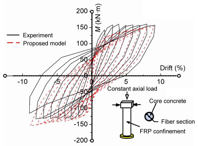
4.2. Cyclic loading full strengthening column tests
In terms of the hysteretic response of FRP confined members, the experiments can be much more complicated compared to monotonic ones, but also to numerical modeling. These FRP confined members tested by Ozbakkaloglu and Saatcioglu (2006) were subjected to a cyclic lateral load, and they were fully strengthened by an FRP tube along the whole members. The selected circular members have a height of 1720 mm and a diameter of 270 mm. The elastic modulus of the FRP tube is 227 GPa, and the nominal thickness is 0.165 mm per ply. The unconfined concrete strength is 49.7 MPa, and the yield stress of eight deformed bars (No. 15) is 500 MPa. The experimental results indicated that the mechanical performance of FRP confined members was conspicuously improved owing to the confinement effect on the increased concrete strength. Fig. 4 also shows a good agreement of numerical simulation results against experimental results.
Fig.4 Comparison results of full strengthening (FRP tube-encased) members under cyclic loading
In detail, the main reason for the difference that the test results exhibit of their obvious asymmetry is supposed to be the relative lateral slippage during the cyclic loading. Moreover, the modified model performs quite well no matter what is the envelope curve or hysteretic response prediction. The ultimate condition of each cycle can be accurately calculated in consistence with the calibration of the axial loading simulation, and the aforementioned fourth modification about the simplified hysteretic rule can efficiently capture the mechanical behavior during the whole cyclic loading process. It is worth pointing out that Lam and Teng (2003)’s model can only be applied in FRP wrapped confined concrete, while the modified model is extended to be able to depict both FRP wrapped and FRP tube-encased confined concretes.
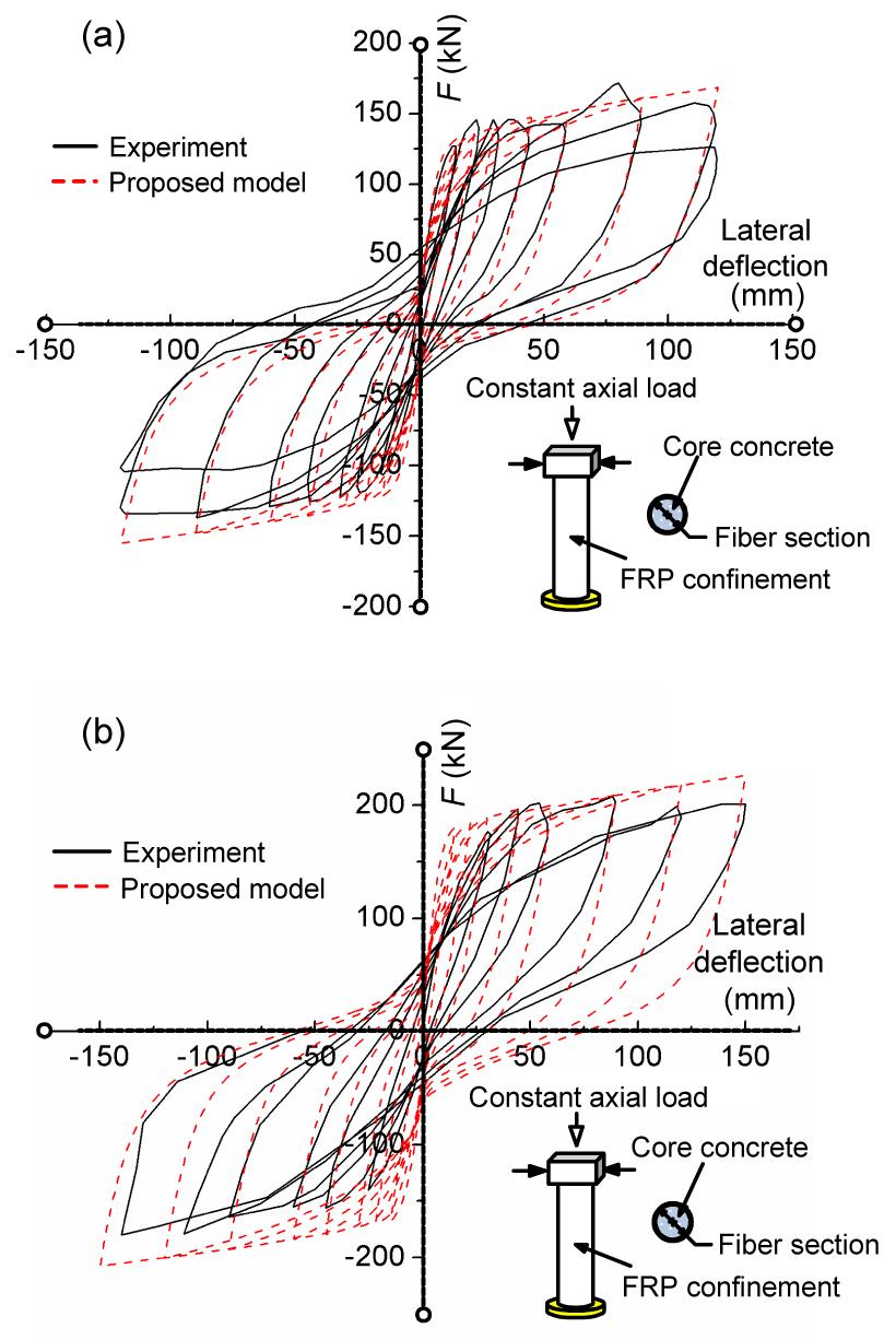
4.3. Cyclic loading partially strengthening tests
The final verification study compares the computational results to a series of typical partially strengthening experiments performed by Shan et al. (2006). As to the existing bridge, this type of strengthening is quite common in China or some other countries. All the test members have a height of 1500 mm and a diameter of 375 mm, and the concrete strength has a range of 34.0 MPa to 41.4 MPa.
To be more practical and economical, the FRP jackets were partially wrapped around the columns concentrating on the vulnerable pier bottom. Take member CCR1 as an example, four layers of FRP jacket were wrapped around at the bottom, while two layers went around the 400 to 800 mm section from the bottom and no FRP confinement above.
The material and geometric properties of the test members are listed in Table 3, and it is obvious that the main difference between the two specimens is the FRP type used for retrofit. Specimen CCR1 is retrofitted by CFRP, while specimen CGR1 is wrapped by GFRP. Generally, the elastic modulus of GFRP is much smaller than CFPR. Nevertheless, the hysteretic response of partially strengthening members with different types and layers of FRP jackets can be both predicted well by the modified model with a uniform expression (Fig. 5). The load deformation curves show a strong correlation for the most part of the cyclic loading process, except for some specific loops.
Table 3
Material and geometric properties of test members in (Shan et al., 2006)’s tests
Specimen
fc0* (MPa)
Retrofit type
EFRP (MPa)
CCR1
30.9
4- or 2-layer CFRP
2.20×10⁵
CGR1
38.7
5- or 2-layer GFRP
3.30×10⁴
Fig.5 Comparison results of partially strengthening members under cyclic loading Predicted and experimental results of FRP confined concrete column (CFRP wrapped) (a) and FRP confined concrete column (GFRP wrapped) (b) under cyclic loading
5. Conclusions
A modified uniaxial constitutive model for FRP confined concrete in circular sections has been proposed and successfully embedded into OpenSees through new material secondary development. With a series of numerical implementations calibrated against test results, the feasibility and accuracy of the proposed modified model were comprehensively verified. Several conclusions can be drawn.
The modified model has raised four main modifications based on a prevalent model proposed by Lam and Teng (2003; 2009). The modifications emphasized on the FRP rupture strain, ultimate stress and strain, intercept stress and hysteretic rules have been stated in detail, respectively. It is not only practical and so-called design-oriented, but also of better generality considering the concrete strength and FRP confinement types.
The computational efficiency of the fiber element method provided by OpenSees is conspicuous, and a fairly numerical precision also can be achieved at the same time. The process of a new material secondary development in OpenSees can be generally used for different materials, so that users can expand their material library according to their specific demand.
With numerical implementations covering a variety of load cases and FRP confinement types for FRP confined members, the utility and accuracy of the proposed model and new material secondary development in OpenSees have been well verified. The modified model performs better than Lam and Teng (2003)’s model in predicting FRP mechanic behavior, especially for high strength FRP confined concrete.
Acknowledgements
The authors greatly appreciate the helpful discussion from Profs. Ya WEI, Quan-wang LI, and Yong-jiu SHI, Tsinghua University, China.
The development of UserMat is actually the whole process of defining a subclass inherited from base class UniaxialMaterial. This base class has a variety of pure virtual methods for the secondary development but no implementation at all, so all declarations should be implemented in the head file, e.g., UserMat.h or source file, i.e., UserMat.cpp (Fig. A1).
Fig.A1 Flow chart of UserMat in OpenSees
The head file plays the role that can complete the class definition of UserMat subclass and the declarations of all global member function. Specifically, the public section presents the lists of the methods available to other classes which can be regarded as its interface; the private section defines variables that are used exclusively in this subclass to fulfill its functions. Therefore, all member functions that will be called in source file should be declared in head file as shown in Fig. A2.
Fig.A2 Code example of UserMat head file
References
[1] BS 8110, 1997. Structural Use of Concrete, Part 1, Code of Practice for Design and Construction. British Standards Institution,London, UK :
[2] He, M.H., Luan, Y.Q., Liu, H., Wang, Z.X., 2013. Development of FRP confined concrete constitutive models and analysis of pier/column behavior based on OpenSees. Bridge Construction, (in Chinese),43(6):22-30.
[3] Hognestad, E., 1951. A Study of Combined Bending and Axial Load in Reinforced Concrete Members. Bulletin Series No. 399. University of Illinois at Urbana Champaign, College of Engineering,Engineering Experiment Station, Urbana :
[4] Karsan, I.D., Jirsa, J.O., 1969. Behavior of concrete under compressive loadings. Journal of the Structural Division, 95(12):2543-2563.
[5] Lam, L., Teng, J.G., 2003. Design-oriented stress-strain model for FRP-confined concrete. Construction and Building Materials, 17(6-7):471-489.
[6] Lam, L., Teng, J.G., 2009. Stress-strain model for FRP-confined concrete under cyclic axial compression. Engineering Structures, 31(2):308-321.
[7] Lim, J.C., Ozbakkaloglu, T., 2013. Confinement model for FRP-confined high-strength concrete. Journal of Composites for Construction, in press,:
[8] Mander, J.B., Priestley, M.J.N., Park, R., 1988. Observed stress-strain behavior of confined concrete. Journal of Structural Engineering, 114(8):1827-1849.
[9] Mander, J.B., Priestley, M.J.N., Park, R., 1988. Theoretical stress-strain model for confined concrete. Journal of Structural Engineering, 114(8):1804-1826.
[10] Miyauchi, K., Inoue, S., Kuroda, T., Kobayashi, A., 1999. Strengthening effects of concrete columns with carbon fiber sheet. Transactions of the Japan Concrete Institute, 21:143-150.
[11] Monti, G., Spacone, E., 2000. Reinforced concrete fiber beam element with bond-slip. Journal of Structural Engineering, 126(6):654-661.
[12] Ozbakkaloglu, T., Saatcioglu, M., 2006. Seismic behavior of high-strength concrete columns confined by fiber reinforced polymer tubes. Journal of Composites for Construction, 10(6):538-549.
[13] Ozbakkaloglu, T., Akin, E., 2012. Behavior of FRP-confined normal- and high-strength concrete under cyclic axial compression. Journal of Composites for Construction, 16(4):451-463.
[14] Ozbakkaloglu, T., Lim, J.C., Vincent, T., 2013. FRP-confined concrete in circular sections: Review and assessment of stress-strain models. Engineering Structures, 49:1068-1088.
[15] Park, R., Negel Priestley, M.J., Gill, W.D., 1982. Ductility of square-confined concrete columns. Journal of the Structural Division, 108(4):929-950.
[16] Samaan, M., Mirmiran, A., Shahawy, M., 1998. Model of concrete confined by fiber composites. Journal of Structural Engineering, 124(9):1025-1031.
[17] Shams, M., Saadeghvaziri, M.A., 1997. State of the art of concrete-filled steel tubular columns. ACI Structural Journal, 94(5):558-571.
[18] Shan, B., Xiao, Y., Guo, Y.R., 2006. Residual performance of FRP-retrofitted RC columns after being subjected to cyclic loading damage. Journal of Composite for Construction, 10(4):304-312.
[19] Spacone, E., Filippou, F.C., Taucer, F.F., 1996. Fiber beam-column model for non-linear analysis of R/C frames: Part I. Formulation. Journal of Earthquake Engineering and Structural Dynamics, 25(7):711-725.
[20] Toutanji, H., 1999. Stress-strain characteristics of concrete columns externally confined with advanced fiber composite sheets. ACI Materials Journal, 96(3):397-404.
[21] Wang, Y.F., Wu, H.L., 2011. Size effect of concrete short columns confined with aramid FRP jackets. Journal of Composites for Construction, 15(4):535-544.
[22] Xiao, Y., Wu, H., 2000. Compressive behavior of concrete confined by carbon fiber composite jackets. Journal of Materials in Civil Engineering, 12(2):139-146.
Open peer comments: Debate/Discuss/Question/Opinion


Open peer comments: Debate/Discuss/Question/Opinion
<1>