1. Introduction
The transport industry has seen rapid developments in recent years. A large amount of effort is expended on improving the technology related to high-speed railways, subways infrastructure and automotive components (Chen and Yu,
2012). Braking systems are one of the most important technologies of high-speed trains, high-value cars and other vehicles, brake discs being the key part of the whole system (Ma et al.,
2011). The material commonly used for manufacture of this kind of component is GG25 grey lamellar graphite cast iron. This material ensures the stability of performance and wear resistance during the whole life of the discs (Cueva et al.,
2003; Thornton et al.,
2011). There are also discs made of carbon matrix composite materials, but used only in racing cars and aircraft brakes due to their high cost. Currently being developed are brake discs using aluminum silicon carbide composites (Fan et al.,
2011; Shivamurthy and Surappaa,
2011). Their weight makes them attractive, but the poor heat dissipation makes this technology unfeasible currently.
Discs are cast parts that are dry-machined using ceramic inserts. Turned surfaces present a characteristic uniform spiral roughness pattern (Taha et al.,
2010), which can cause problems during the first braking. In some cases it causes noise, vibration or deviation in the trajectory of the vehicle. To avoid these problems and to optimize the braking force, the spiral pattern of the turning process has to be eliminated. This fact is becoming a major problem for discs manufacturers, who try to deliver disks to develop their full braking potential in all the braking processes, even in the first braking. A conventional solution adopted by manufacturers is grinding, but only market leaders can offer this service due to its high cost.
Commonly, vibration problems in this field are known as judder and squeal. The first one is an error state with partial brake load and stick-slip oscillations. It can take place in clutch or brake systems. Stick-slip oscillations are also friction induced (Centea et al.,
1999;
2001). The second one usually occurs in the frequency range between 1 and 16 kHz. Some studies showed the importance of the disc topography in the generation of automotive disc brake vibrations (Heussaff et al.,
2012; Yoon et al.,
2012). Some commonly used techniques to reduce noise and squeal, and solve other important problems during the braking process can be shot-blasting (Bergman et al.,
1999) and grit-blasting (Hammerström and Jacobson,
2006). The main idea is to change the friction characteristics of the initial surface avoiding the typical turning pattern.
Nowadays, but only when a customer requires it, the tracks of the brake disc are ground. This process is performed on large and expensive grinding machines. Despite the developments in grinding technology and lubrication systems (Sanchez et al.,
2010), grinding is a costly process in which usually much of the installation equipment comprises the lubrication system. In this paper, a cost-effective technique to achieve the ideal quality finish of the discs is proposed, avoiding large investments in machinery and allowing the manufacturer to offer ground disks to all their customers. There are some techniques for finishing and polishing surfaces apart from grinding, such as burnishing (Rodríguez et al.,
2012), laser polishing (Ukar et al.,
2010) or even shot-peening (Chaise et al.,
2012). Nevertheless, in this work the brushing technology was investigated.
Brushing is a production technique that has been used for many years in manual and semi-automatic processes of surface finishing. Apart from optimizing the surface of machined parts, it is also possible to remove burrs and marks with filamentary brushes (Mathai and Melkote,
2012; Chen and Yu,
2012). Brushes can be made of natural fibre, metallic wire or abrasive-filled polymeric fibres and there are many different types available. There are for example wheel brushes, cup brushes, end brushes, and abrasive ball honing brushes which are employed depending on the current process and part (Gillespie,
1999).
To remove material, the rotating cutting-fibres with special geometries exert a force on the surface of the workpiece. This force depends on the rotation speed (
S), the depth of cut (
a
p) and the feed rate (
F), and it has a huge influence on the quality of the surface. With orthogonal use of cup-brushes, the rotation speed leads to a spread of the fibres due to the centrifugal force and thus shortens and widens the cutting-fibres especially on the outer face of the brush. Thus, there is a limit to the rotation speed depending on the type of brush and its diameter. Some studies developed models focused on the dynamic behaviour of rotating brushes (Vanegas-Useche et al.,
2008;
2011) or on finite element models of the brushing process (Wahab et al.,
2007; Vanegas-Useche et al.,
2011a;
2011b). However, there is no more information in the literature about this, so it is difficult to find the best parameters which are needed to achieve the optimal result. Due to the deformation of the fibres and the fact that the brushes are ductile, the material removed is much less than the adjusted nominal depth of cut (
a
pn).
Nylon/abrasive brushing tools are used in surface finishing processes for a wide range of applications, such as blending, polishing, and edge-radii (Overholser et al.,
2003). These flexible brushing tools can easily be adopted in milling, turning or grinding machines so that there is no necessity to invest in new machinery. Moreover, brushing is a simple, cost-effective, and versatile method for polishing surfaces with similar input parameters as other conventional machining processes (Zhang and Li,
2010; Liu et al.,
2011).
In this paper, the brushing process to eliminate the spiral roughness pattern of a previous turning process and to optimize the surface of the machined part is presented. The main goal is to eliminating the turning pattern, avoiding noise and vibrations on brake discs, and increasing the braking-force, especially during the first braking. Therefore, two different nylon-abrasive brushes which are recommended for finishing the automatic-processes are used. Many different process parameters and strategies which have influences on the surface quality after brushing are examined in this work.
2. Experimental
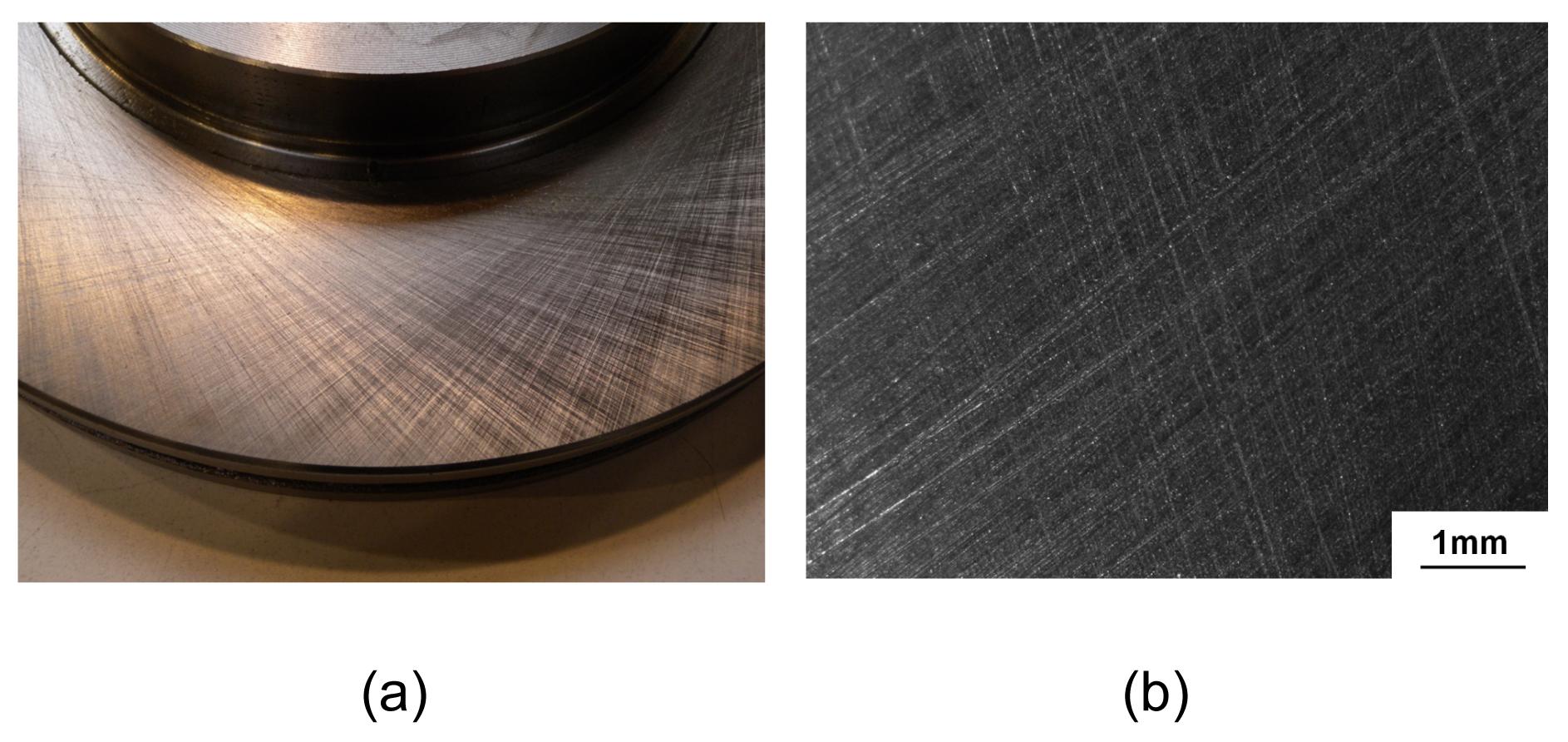
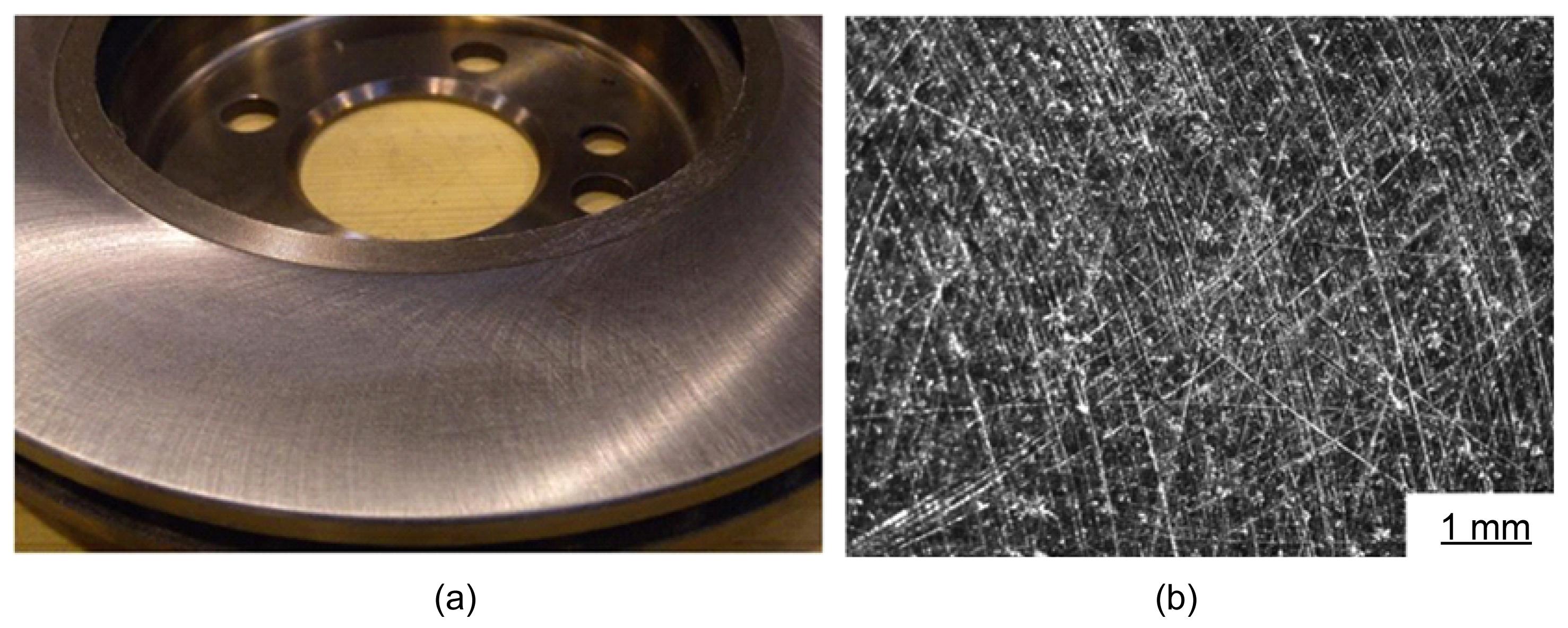
The objective of this work is to obtain a finished surface on disc tracks similar to the ground surface (Fig.
1). Thus, disc manufacturers can offer quality discs to their customers without the need for a costly grinding process. For this purpose it is necessary to achieve an average roughness (
R
a) less than 1 μm (disc manufacturer requirement) and anisotropic surface pattern. There are two mechanisms in dry boundary friction. These are ploughing friction, where roughness features (asperities) of the harder surface (in this case the brake pad) try to plough through the softer asperities of the brake disc. This causes friction by a combination of elastic and plastic deformation of roughness features. The other mechanism is fusing the roughness of two surfaces together under pressure, with friction being the result of braking at these junctions. This form of friction is called adhesive friction. Adhesion is increased with smoother surfaces and similar contacting materials. Ploughing is increased with rougher surfaces (Gohar and Rahnejat,
2008).
Fig.1
Target surface (a) and non-uniform roughness pattern (b)
Brushing tests were carried out in a CMZ turning center (model TC25BTY) with a Fanuc numerical control (model 31iT HVi). Two different commercial cup brushes with nylon abrasive filaments were selected for this work and fixed in a conventional toolholder. The first brush selected (Type I) was an alumina (Al
2O
3) cutting fibre brush and the second one (Type II) contained a combination of both ceramic and silicon carbide (SiC) filaments. Nylon, which is used as binder, is an ideal material for a brush filament. It has excellent toughness and fatigue properties as well as moisture, abrasion, and chemical resistance compared to other polymers. Both tools were especially designed for polishing parts made of cast iron.
2.1. Influence of brushing parameters
In this section, a wide range of parameters were evaluated in order to determine their influence on the final roughness and surface pattern. The aim of the proposed test was to establish the optimum brushing conditions, to achieve the required surface quality. An experimental matrix was performed using two different type of brushes and different values of the nominal depth of cut and feed rate. Tests were divided into two phases. The first one studied the feasibility of the two abrasive types and also provided a first approach to the optimum parameters.
The first step in the industrial application of this process is to establish the know-how of the process itself. To achieve it, tests were conducted in order to study the influence of the brushing parameters, the tool life behavior, the multiple passes influence, and the force-displacement correlation.
The second one used the results obtained in the first one and the best abrasive type was used with a small range of variation in the parameters. This second phase provided a more detailed analysis of the influence of process parameters. Values used in both phases are shown in Table
1. To avoid the influence of tool wear in these tests, brushes were resharpened after every test using a grinding stone.
Table 1
Process parameters used in experimental tests
| Phase |
a
pn (mm) |
F (mm/min) |
S (r/min) |
Type |
| I |
0.5, 1, 1.5, 2 |
500, 1000, 1500, 2000 |
2500 |
Al2O3, SiC |
| II |
0.5, 1, 1.5 |
1250, 1500, 1750 |
2500 |
Al2O3
|
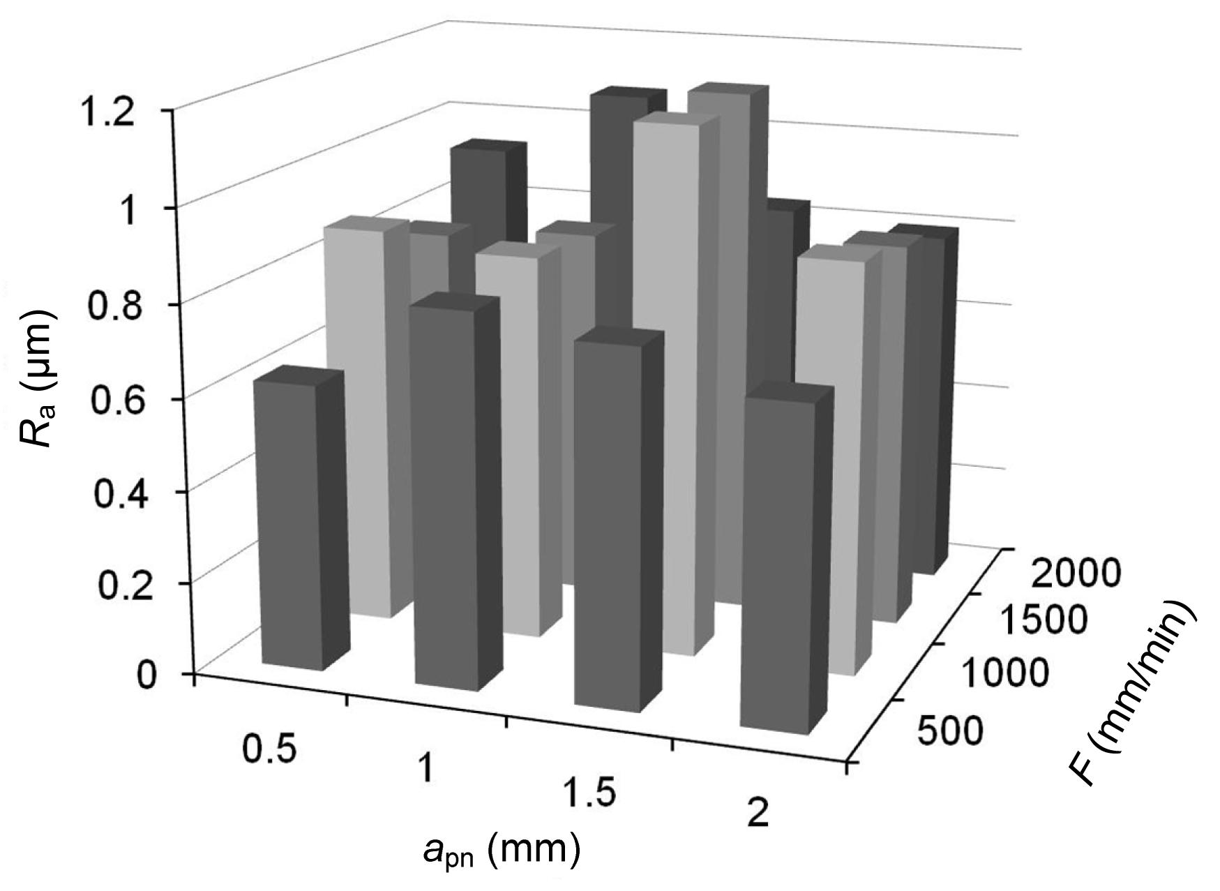
Results for the Type I brush are shown in Fig.
2. The roughness parameters improved notably and the surface pattern was eliminated. Values of the nominal depth of cut between 0.5 mm and 1 mm provided the best results. Using values around 0.5 mm, the spiral pattern was barely eliminated. Using values higher than 1 mm the spiral pattern was fully eliminated but numerous grooves were derived from the carbon particle detachment. Regarding the feed rate, the best results occurred at lower speeds. At speeds between 500 mm/min and 1500 mm/min the desired qualities remained.
Fig.2
Surface roughness for different brushing conditions obtained using the Type I brush
Fig.
3 shows the results obtained with the Type II brush. It is shown that there is hardly any improvement in the roughness while using this brush. Even with a nominal depth of cut of 2 mm, the marks of the previous turning process cannot be eliminated. Roughness only improved barely and the peaks were still nearly as high as before the brushing process. The results show that the Type II brush was not useful in eliminating the roughness pattern of a previous turning process, so the following optimization tests were made using only the Type I brush.
Fig.3
Surface roughness for different brushing conditions obtained using the Type II brush
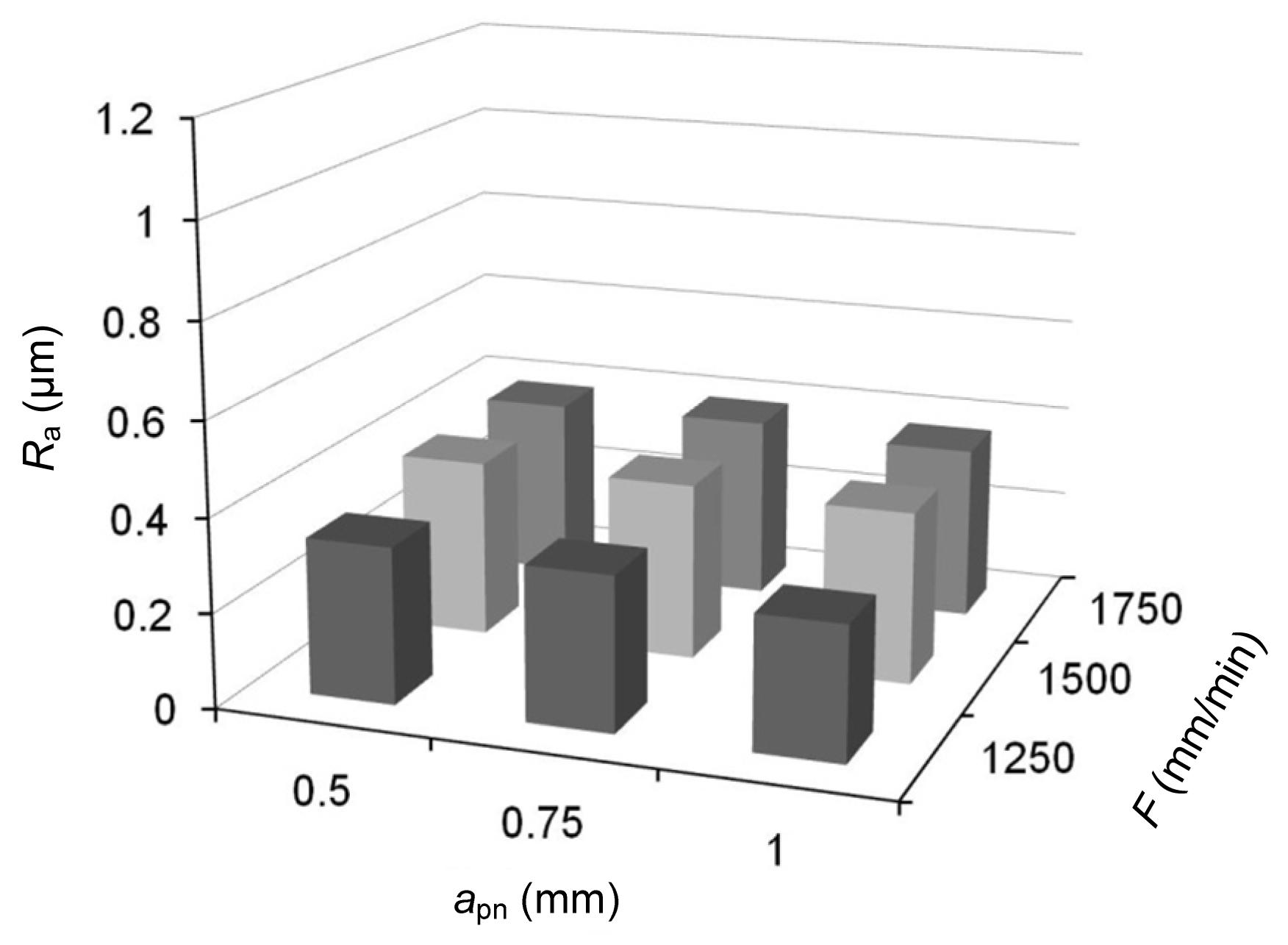
In the second phase of tests, the Type I brush was used and the process parameters were analyzed in a small variation range. As in Phase I, the best results occurred to nominal depths of cut around 1 mm and feed rates around 1500 mm/min. Fig.
4 shows that the variation in the surface quality is not significant in this range of parameters.
Fig.4
Surface roughness obtained in Phase II using the Type I brush
2.2. Tool life tests
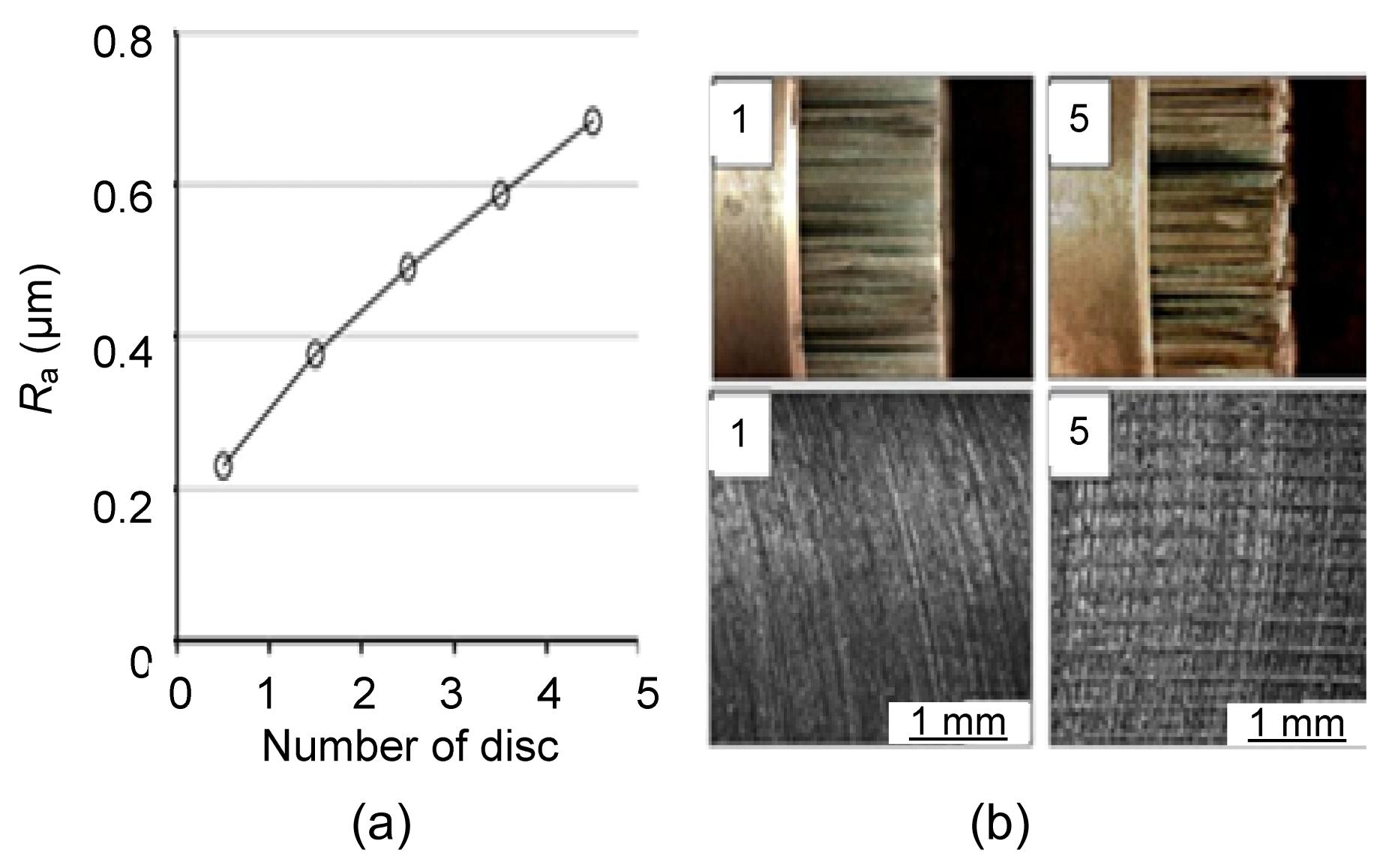
In this section the tool wear influence was studied. Five discs were brushed using the optimum parameters. The idea is to compare the roughness parameters obtained and to measure the tool wear. Fig.
5 shows that the achieved roughness increases rapidly with the increase in tool wear.
The initial brush filaments, the final wear, and the corresponding surfaces are also shown in Fig.
5. After brushing five discs, several filaments of the brushing tool were abraded. The abrasion rate of the outer filaments was faster due to the higher speed and larger cutting forces. Results show that brushing several discs without resharping the tool does not leas to elimination of the roughness pattern. Taking into account these results, it is clear that shape recovery is important to fully eliminate the directional surface pattern. Thus, it is important to resharpen the brush regularly using a grinding stone. Type I brushes can be resharpened around 50–80 times per tool.
Fig.5Influence of tool wear on roughness (a); Detail of the tool wear and surface quality obtained (b)
In Fig.
5b, 1 and 5 mean after one disc and five discs, respectively
2.3. Multiple passes influence
Another input variable to take into account is the number of brushing passes performed. To figure out if multiple brushing has any benefit on the achieved surface, some tests were performed. Tests consist of performing the brushing process several times in the same disc (from one to five times), and then comparing the achieved results.
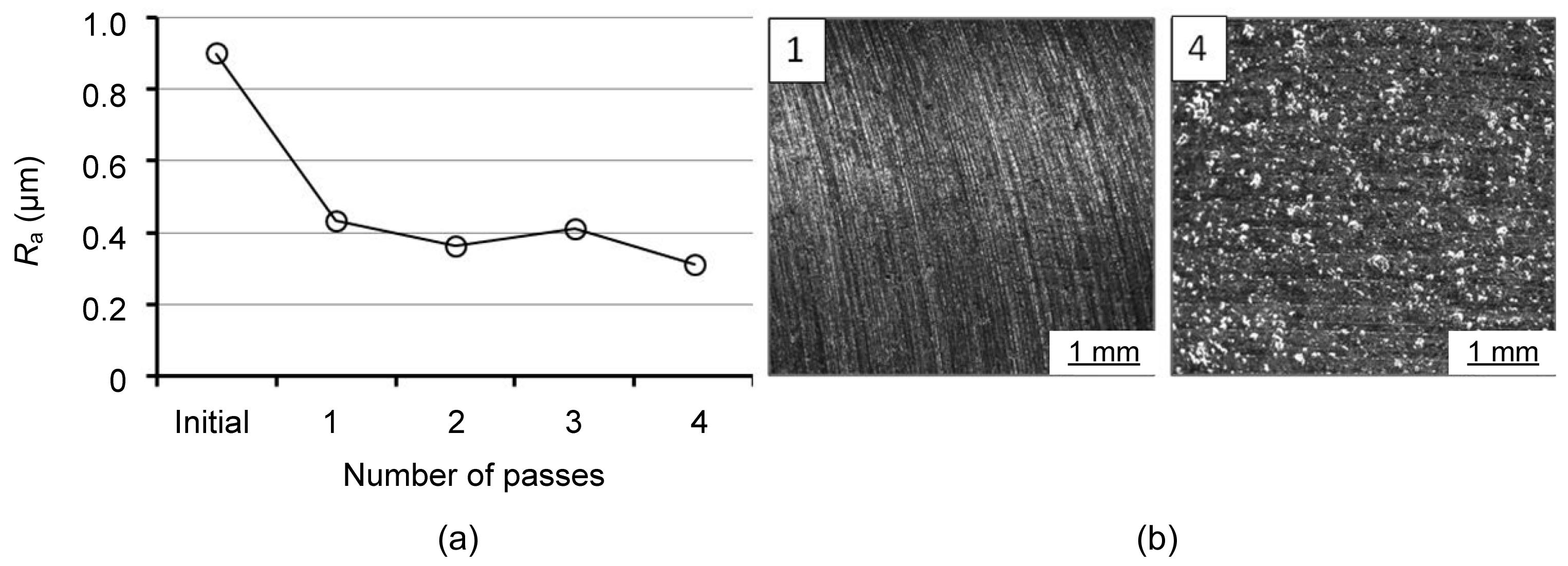
Fig.
6 shows that both the roughness after one brushing and after four brushings were nearly the same. It is conspicuous that after brushing more than one time many more carbon particles are removed and a great number of small holes were created on the disc. Due to the facts mentioned above, there is technically no value in brushing a surface more than once.
Fig.6Influence of multiple passes on surface roughness (a) and detail of the surface obtained (b)
In Fig.
6b, 1 and 4 mean after one disc and four discs, respectively
2.4. Brushing forces measurement
The normal force during the process is a very important parameter in characterizing the polishing capacity, which is directly related to the nominal depth of cut. Forces were measured to a nominal depth of cut of 1 mm, which was considered as optimal for this process. The measurements show that under these conditions the forces exerted by the brush on the surface were around 15–20 N. In order to control the process, it is desirable to control the brushing force to maintain a constant rate during the brushing process.
3. Prototypes
Once the process parameters were established, in this section the full brushing process was performed on 10 prototype discs. The objective of these tests was to manufacture test parts to be measured and validated against the specifications required for these components. The parameters used in the tests were
S=2500 r/min,
a
pn=1 mm and the Type I brush was used. As shown in Fig.
7, the track surface obtained does not show the typical turning pattern 1, and the non-uniform pattern is similar to the ground surface.
Fig.7
Final surface obtained that is similar to the one obtained using conventional grinding process (a) and detail of the non-uniform surface pattern (b)
3D surface topographies are shown in Figs.
8a and 8b, where the process time was less than 5 s. It is shown that the initial surface presented the ridges and valleys surface characteristics of turning and consequently the spiral pattern. The initial roughness was about 1 μm. The same surface after being brushed showed roughness parameters reduced to 75%, and the roughness pattern disappeared.
Fig.8
3D topography of the turned surface (a) and brushed surface (b)
Ra: average roughness; Rz: mean roughness depth
Having achieved the target surface, the most representative geometrical characteristics of the part were measured. Table
2 shows that these characteristics barely changed during the brushing process. Results before and after brushing differed in no more than 0.002 mm for the thickness variation, 0.005 mm for the track run out and 0.002 mm for the circumferential straightness. Consequently, all the prototypes matched perfectly with the specifications.
Table 2
Geometrical characteristics measurement before and after brushing process
| Disc |
Circumferential thickness variation, σ=0.01 mm
|
Outer track run out, σ=0.03 mm
|
Inner track run out, σ=0.03 mm
|
Outer track circumferential straightness, σ=0.015 mm
|
Inner track circumferential straightness, σ=0.015 mm
|
| Before |
After |
Before |
After |
Before |
After |
Before |
After |
Before |
After |
| 1 |
0.003 |
0.003 |
0.007 |
0.007 |
0.008 |
0.005 |
0.002 |
0.002 |
0.002 |
0.002 |
| 2 |
0.003 |
0.005 |
0.012 |
0.014 |
0.010 |
0.011 |
0.002 |
0.002 |
0.002 |
0.002 |
| 3 |
0.002 |
0.004 |
0.010 |
0.014 |
0.012 |
0.015 |
0.002 |
0.004 |
0.002 |
0.004 |
| 4 |
0.004 |
0.002 |
0.014 |
0.016 |
0.017 |
0.015 |
0.003 |
0.003 |
0.004 |
0.003 |
| 5 |
0.004 |
0.005 |
0.012 |
0.019 |
0.011 |
0.015 |
0.001 |
0.002 |
0.002 |
0.003 |
| 6 |
0.003 |
0.003 |
0.016 |
0.016 |
0.019 |
0.018 |
0.003 |
0.002 |
0.004 |
0.003 |
| 7 |
0.002 |
0.005 |
0.014 |
0.015 |
0.013 |
0.014 |
0.003 |
0.004 |
0.003 |
0.003 |
| 8 |
0.002 |
0.003 |
0.017 |
0.016 |
0.018 |
0.018 |
0.007 |
0.007 |
0.007 |
0.007 |
| 9 |
0.002 |
0.002 |
0.016 |
0.017 |
0.016 |
0.017 |
0.002 |
0.003 |
0.002 |
0.003 |
| 10 |
0.002 |
0.003 |
0.017 |
0.013 |
0.019 |
0.014 |
0.004 |
0.004 |
0.004 |
0.004 |
4. Conclusions
Brushing techniques were presented as a cost-effective alternative to conventional grinding for finishing brake disc tracks. A complete study of the brushing process was carried out and some prototypes were polished in order to check the feasibility of the process. Based on the experimental results achieved, the following conclusions are derived:
-
Alumina fibre brushes are the most suitable for the correct surface modification of brake discs.
-
A nominal depth of cut of 1 mm (equivalent to a force value of 15–20 N) provides the best finishing results.
-
The correct rotating speed of the brush is the maximum recommended by the manufacturer (2500 r/min).
-
The feed rate recommended for discs brushing depends on the quality required. At productive speeds, the results are acceptable.
-
The brushes wear rapidly, which are easily recovered with a grinding stone and can be recovered more than 50–80 times per tool.
-
It has technically no worth brushing a surface more than once because the roughness hardly improves and more holes in the cast iron surface are created by removing carbon particles.
Brushing improves the surface quality and eliminates the spiral roughness pattern. This fact, along with the advantage of brushing on the same turning machine, makes brushing suitable as a fast and simple finishing technique, significantly reducing the processing time compared to other conventional techniques.
* Project supported by the Etortek proFUTURE II Project and UPV/EHU (No. UFI 11/29), SpainReferences
[1] Bergman, F., Eriksson, M., Jacobson, S., 1999. Influence of disc topography on generation of brake squeal.
Wear, 225-229:621-628.

[2] Centea, D.N., Rahnejat, H., Menday, M.T., 1999. The influence of interface coefficient of friction upon propensity to judder in automotive clutches.
Journal of Automobile Engineering, 213(3):245-258.
[3] Centea, D.N., Rahnejat, H., Menday, M.T., 2001. Non-linear multi-body dynamic analysis for the study of clutch torsional vibrations (judder).
Applied Mathematical Modelling, 25(3):177-192.
[4] Chaise, T., Li, J., Nlias, D., 2012. Modelling of multiple impacts for the prediction of distortions and residual stresses induced by ultrasonic shot peening (USP).
Journal of Materials Processing Technology, 212(10):2080-2090.
[5] Chen, R., Yu, X., 2012. Towards safe and comfortable high-speed transportation infrastructure.
Journal of Zhejiang University-SCIENCE A (Applied Physics & Engineering), 13(11):799-801.
[6] Cueva, G., Sinatora, A., Guesser, W.L., 2003. Wear resistance of cast irons used in brake disc rotors.
Wear, 255(7-12):1256-1260.
[7] Fan, S., Zhang, L., Cheng, L., 2011. Microstructure and frictional properties of C/SiC brake materials with sandwich structure.
Ceramics International, 37(7):2829-2835.
[8] Gillespie, L.K., 1999. Deburring and Edge Finishing Handbook. Society of Manufacturing Engineers,Dearborn, Michigan, USA :
[9] Gohar, R., Rahnejat, H., 2008. Fundamentals of Tribology. Imperial College Press,UK :
[10] Hammerstrm, L., Jacobson, S., 2006. Surface modification of brake discs to reduce squeal problems.
Wear, 261(1):53-57.
[11] Heussaff, A., Dubar, L., Tison, T., 2012. A methodology for the modeling of the variability of brake lining surfaces.
Wear, 289:145-159.
[12] Liu, P., Xu, J., Fu, Y., 2011. Cutting force and its frequency spectrum characteristics in high speed milling of titanium alloy with a polycrystalline diamond tool.
Journal of Zhejiang University-SCIENCE A (Applied Physics & Engineering), 12(1):56-62.
[13] Ma, J., Zhang, B., Huang, X., 2011. Design and analysis of the hybrid excitation rail eddy brake system of high-speed trains.
Journal of Zhejiang Universit-SCIENCE A (Applied Physics & Engineering), 12(12):936-944.
[14] Mathai, G., Melkote, S., 2012. Effect of process parameters on the rate of abrasive assisted brush deburring of microgrooves.
International Journal of Machine Tools and Manufacture, 57:46-54.
[15] Overholser, R.W., Stango, R.J., Fournelle, R.A., 2003. Morphology of metal surface generated by nylon/abrasive filament brush.
International Journal of Machine Tools and Manufacture, 43(2):193-202.
[16] Rodrguez, A., Lpez de Lacalle, L.N., Celaya, A., 2012. Surface improvement of shafts by the deep ball-burnishing technique.
Surface and Coatings Technology, 206(11-12):2817-2824.
[17] Sanchez, J.A., Pombo, I., Alberdi, R., 2010. Machining evaluation of a hybrid MQL-CO
2 grinding technology.
Journal of Cleaner Production, 18:1840-1849.
[18] Shivamurthy, R.C., Surappaa, M.K., 2011. Tribological characteristics of A356 Al alloy-SiCP composite discs.
Wear, 271(9-10):1946-1950.
[19] Taha, Z., Lelana, H., Aoyama, H., 2010. Insert geometry effects on surface roughness in turning process of AISI D2 steel.
Journal of Zhejiang University-SCIENCE A (Applied Physics & Engineering), 11(12):966-971.
[20] Thornton, R., Slatter, T., Jones, A.H., 2011. The effects of cryogenic processing on the wear resistance of grey cast iron brake discs.
Wear, 271(9-10):2386-2395.
[21] Ukar, E., Lamikiz, A., Lpez de Lacalle, L.N., 2010. Laser polishing of DIN 1.2379 tool steel with CO
2 laser and high-power diode laser.
International Journal of Machine Tools and Manufacture, 50(1):115-125.
[22] Vanegas-Useche, L.V., Wahab, M.M.A., Parker, G.A., 2008. Dynamics of a freely rotating cutting brush subjected to variable speed.
International Journal of Mechanical Sciences, 50(4):804-816.
[23] Vanegas-Useche, L.V., Abdel, M.M., Parker, G.A., 2011. Dynamic finite element model of oscillatory brushes.
Finite Elements in Analysis and Design, 47(7):771-783.
[24] Vanegas-Useche, L.V., Abdel, M.M., Parker, G.A., 2011. Determination of friction coefficients, brush contact arcs and brush penetrations for gutter brush-road interaction through FEM.
Acta Mechanica, 221(1-2):119-132.
[25] Wahab, M.A., Parker, G., Wang, C., 2007. Modelling rotary sweeping brushes and analyzing brush characteristic using finite element method.
Finite Elements in Analysis and Design, 43(6-7):521-532.
[26] Yoon, S.W., Shin, M.W., Lee, W.G., 2012. Effect of surface contact conditions on the stick-slip behavior of brake friction material.
Wear, 294-295:305-312.
[27] Zhang, S., Li, J., 2010. Tool wear criterion, tool life, and surface roughness during high-speed end milling Ti-6Al-4V alloy.
Journal of Zhejiang University-SCIENCE A (Applied Physics & Engineering), 11(8):587-595.


Open peer comments: Debate/Discuss/Question/Opinion
<1>