Affiliation(s):
1.
School of Mechatronics Engineering, Harbin Institute of Technology, Harbin 150001, China; moreAffiliation(s): 1.
School of Mechatronics Engineering, Harbin Institute of Technology, Harbin 150001, China; 2.
Shenyang Institute of Automation, Chinese Academy of Science, Shenyang 110016, China; less
Xiao-biao Shan, Shi-wei Guan, Zhang-shi Liu, Zhen-long Xu, Tao Xie. A new energy harvester using a piezoelectric and suspension electromagnetic mechanism[J]. Journal of Zhejiang University Science A, 2013, 14(12): 890-897.
@article{title="A new energy harvester using a piezoelectric and suspension electromagnetic mechanism", author="Xiao-biao Shan, Shi-wei Guan, Zhang-shi Liu, Zhen-long Xu, Tao Xie", journal="Journal of Zhejiang University Science A", volume="14", number="12", pages="890-897", year="2013", publisher="Zhejiang University Press & Springer", doi="10.1631/jzus.A1300210" }
%0 Journal Article %T A new energy harvester using a piezoelectric and suspension electromagnetic mechanism %A Xiao-biao Shan %A Shi-wei Guan %A Zhang-shi Liu %A Zhen-long Xu %A Tao Xie %J Journal of Zhejiang University SCIENCE A %V 14 %N 12 %P 890-897 %@ 1673-565X %D 2013 %I Zhejiang University Press & Springer %DOI 10.1631/jzus.A1300210
TY - JOUR T1 - A new energy harvester using a piezoelectric and suspension electromagnetic mechanism A1 - Xiao-biao Shan A1 - Shi-wei Guan A1 - Zhang-shi Liu A1 - Zhen-long Xu A1 - Tao Xie J0 - Journal of Zhejiang University Science A VL - 14 IS - 12 SP - 890 EP - 897 %@ 1673-565X Y1 - 2013 PB - Zhejiang University Press & Springer ER - DOI - 10.1631/jzus.A1300210
Abstract: This study presents a new design of a piezoelectric-electromagnetic energy harvester to enlarge the frequency bandwidth and obtain a larger energy output. This harvester consists of a primary piezoelectric energy harvesting device, in which a suspension electromagnetic component is added. A coupling mathematical model of the two independent energy harvesting techniques was established. Numerical results show that the piezoelectric-electromagnetic energy harvester has three times the bandwidth and higher power output in comparison with the corresponding stand-alone, single harvesting mode devices. The finite element models of the piezoelectric and electromagnetic systems were developed, respectively. A finite element analysis was performed. Experiments were carried out to verify the validity of the numerical simulation and the finite element results. It shows that the power output and the peak frequency obtained from the numerical analysis and the finite element simulation are in good agreement with the experimental results. This study provides a promising method to broaden the frequency bandwidth and increase the energy harvesting power output for energy harvesters.
Darkslateblue:Affiliate; Royal Blue:Author; Turquoise:Article
Article Content
1. Introduction
The energy harvesting from ambient environmental vibration sources has been widely studied over the past decades for its promising energy density and ease of acquisition (Beeby et al., 2006; MacCurdy et al., 2008; Yang et al., 2010; Wang et al., 2012). Piezoelectric and electromagnetic are the most effective way of turning mechanical vibrations into electrical energy (Roundy et al., 2004; Wacharasindhu and Kwon, 2008; Tadesse et al., 2009; Yuan et al., 2009; Wang et al., 2013). To enhance the energy conversion efficiency, researchers proposed a kind of hybrid energy harvesting technology by coupling the piezoelectric and the electromagnetic mechanism together.
The hybrid energy harvester has received great attention for its important advantages, such as being clean, stable, having high energy density, and a wide frequency band. For example, a general spring-mass-damper model was presented by Williams and Yates (1996), where the electrical energy harvested was equivalent to the energy dissipated in the electrical damping. The spring-mass-damper model was widely used by simplifying the effect of two complex mechanisms into viscous damping. Challa et al. (2009) generated 332 μW at 21.6 Hz from a cantilever beam hybrid energy harvester. This harvester produced a 30% increase in power output compared to 257 μW and 244 μW generated from the stand-alone piezoelectric and electromagnetic energy harvesting devices, respectively. Wischke et al. (2009) presented a model of a hybrid generator which was based on a beam suspended on both sides. Gonsalez et al. (2010) conducted a model considering the coupling influences between the piezoelectric and electromagnetic systems. They found that the mechanical system was strongly influenced when an electrical circuit was coupled to the transducer.
From the above descriptions, it can be found that the previous devices can have effective outputs only when they work near their optimal frequencies. However, it is difficult to achieve a high power output from a low frequency vibration in the environment. Therefore, a new hybrid energy harvester is presented to broaden the frequency bandwidth and coordinate ambient low-frequency vibration. Firstly, the mathematical model of the hybrid energy harvester will be established. Secondly, the corresponding numerical simulation will be performed. Finally, the validity of the mathematical model will be verified through a finite element simulation and supporting experiments.
2. Mathematical modeling
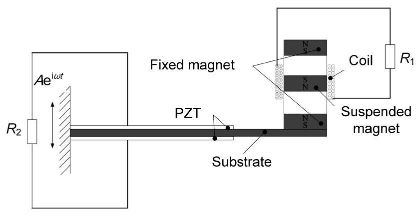
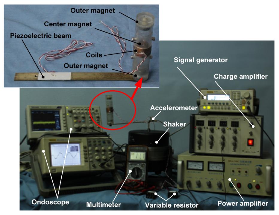
Fig. 1 illustrates a schematic of the newly presented hybrid energy harvester. This harvester consists of a Pb(Zr,Ti)O3 (PZT) bimorph cantilever beam mounted on the vibrating shaker and a magnetic levitation system fixed on the PZT beam. The magnetic levitation system used two outer magnets that were mechanically attached to a support. A center magnet was placed between the two outer magnets. The magnetic poles were oriented to repel the center magnet. Thus, the center magnet was suspended by a nonlinear restoring force (Mann and Owens, 2010). Spiral coils were wound around the outer casing to transform the mechanical energy of the center magnet to electrical energy.
Fig.1 Schematic of a hybrid energy harvester
2.1. Spring-mass-damper model
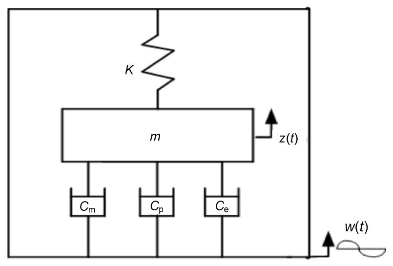
In this section, the hybrid energy harvester device can be simplified as a spring-mass-damper system (Fig. 2), consisting of a mechanical damping Cm (which accounts for the energy losses due to structural and viscous damping), a piezoelectric damping Cp, and an electrical damping Ce.
Fig.2 Schematic of the spring-mass-damper system
Here the vibrating structure is represented as a spring with a stiffness K and a mass m. A source vibration of w(t)=Acos(ωt) (where A and ω are source vibration amplitude and frequency, respectively) generates a relative deflection z(t) in the vibrating structure. A differential equation using the above-described model is given as
,
where ωn is the undamped natural frequency of the vibrating structure, , and ζ is the total damping ratio, .
The solution of Eq. (1) can be divided into two parts, i.e., the transient solution and the steady-state solution. The transient solution is caused by the beginning unstable vibration or disturbance of the system itself. So the transient solution is ignored, by retaining the steady-state solution.
,
where θ is the phase difference and it can be ignored for having almost no effect on the power output.
In the hybrid power generation device, z(t) represents the vibration of the piezoelectric beam, that is, the electromagnetic energy harvester device input vibration.
2.2. Power output from a stand-alone electromagnetic energy harvester
Before starting to build the mathematical model of the magnetic suspension energy harvester, one should know the expression of the acting force between a fixed permanent magnet and a vibrating magnet. There are some empirical formulas for solving the above acting force. However, these empirical formulas can only provide an approximate result. To establish a more accurate model for a magnetic suspension system, the software MAXWELL was used to obtain the acting force, and to efficiently and accurately solve the electromagnetic field simulation directly from the actual model.
Fig. 3 illustrates the relationship between the restoring force and the separation distance of two magnets simulated by MAXWELL. A polynomial curve-fitting algorithm in MATLAB was employed based on the above relationship. It can be found that the cubic polynomial fitting can effectively meet the accuracy requirements (Fig. 3).
Fig.3 Relationship between the restoring force and the separation distance of two magnets and the cubic polynomial fitting
Therefore, according to the fitting results, the force between the two magnets can be written as ,
where s is the separation distance between two magnets, and the coefficients b0, b1, b2, and b3 are obtained using MATLAB.
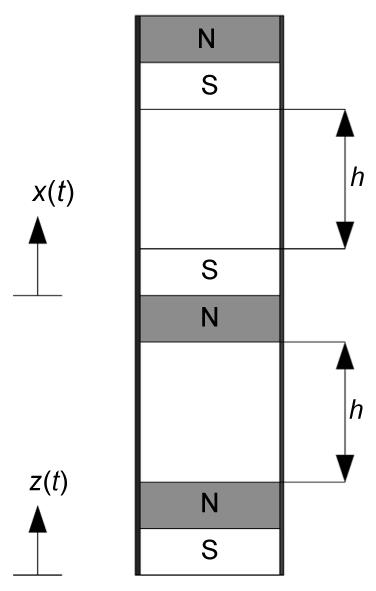
To determine the restoring forces of the suspension electromagnetic system, Fig. 4 illustrates a schematic diagram of the magnetic levitation system.
Fig.4 Schematic of the magnetic levitation system
Hence, when the suspended magnet deviates as displacement y from the equilibrium position, the total magnetic restoring force can be calculated as
where h stands for the separation distance between the fixed magnets and the suspension magnet, and the coefficients are k1=39.5 N/m, k3=97 320 N/m3.
According to (Mann and Sims, 2009), a governing equation is given as
,
where m0 is the magnet mass; g is the gravitational constant; Cem is the damping coefficient used to describing the mechanical damping; x is the motion of the center magnet; i is the electrical current; and α is the electromechanical coupling coefficient. This term is commonly expressed as α=NBL, where N is the number of coil turns, B is the average magnetic field strength, and L is the coil length.
According to (Stephen, 2006), the coil magnetic force is assumed to be proportional to the relative velocity between the center magnet and outer housing, , where Re is the internal resistance of the coil, and R1 is the resistance of the external load. To obtain the power output from a stand-alone electromagnetic energy harvester, the input acceleration A0 remains unchanged, so . Ce describes the combined mechanical and electrical damping of the magnetic levitation system, Ce=Cet+Cem, where Cet is the expression for the electrical damping coefficient, . Substituting y(t)=x(t)−z(t) into Eq. (5), we can obtain a governing equation written in terms of the relative displacement between the center magnet and outer housing.
,
where the coefficients of Eq. (5) have been rewritten as A0=2εF1, , , −g=F0, , and ε has been introduced as a parameter (Mann and Sims, 2009).
Eq. (6) is a second-order nonlinear differential equation. The following is the process of solving this equation using a multiple time scale. The assumed solution to Eq. (6) is written as a first-order expansion.
.
The independent time scales are defined as τ0=t, τ1=εt. It follows that the derivatives with respect to time become partial derivatives with respect to the corresponding time scale after setting and .
,
.
Substituting Eqs. (8) and (9) into Eq. (6) and separating the result into the orders of ε, the following two linear expressions can be obtained:
,
.
The solution of Eq. (10) can be written as
,
where A(τ1) and Ā(τ1) are complex conjugates that are functions of τ1.
After setting ω=ω0+εσ, and substituting Eq. (12) into Eq. (11), the following expression can be obtained:
,
where O(einω0τ0) is the polynomial that n≠1, σ is called a detuning parameter for describing the nearness of ω and ω0. In the method of multiple time scale, the secular terms equal 0.
.
According to (Nayfeh and Balachandran, 2008), the polar forms, and , are now introduced into the above equation. After substituting γ=στ1−Φ=(ω−ω0)τ0−Φ and separating into the real and imaginary components, the resulting equations are
,
.
The equilibrium solutions of Eqs. (15) and (16) represent the steady-state periodic solutions of the system. They can be found by setting and . Squaring and adding these relationships results into the expression of the frequency response for the nonlinear system, the initial parameters are introduced into the expression. Then, the modified frequency response equation is as follows:
Thus, the output power of the electromagnetic energy harvester can be expressed as
.
2.3. Power output from a stand-alone piezoelectricity energy harvester
In this section, a double-chip piezoelectric cantilever is used. The open voltage Up generated by the piezoelectric effect depends on the stress σstruc and the material properties of PZT, which was given by Challa et al. (2009)
,
where tp is the thickness of the piezoelectric ceramic, d31 is the piezoelectric strain constant, and ε is the dielectric constant of the piezoelectric material.
As mentioned in the context, z(t) represents the vibration of the piezoelectric beam. After setting A1 and the acceleration of z(t), the equivalent force exerting on the piezoelectric beam can be expressed as
.
The average bending stress of the piezoelectric film can be written as
,
where L is the thickness of the piezoelectric ceramic, Lp and hp are the length and thicknesses of the substrate, respectively, and I is the equivalent area moment, .
By inserting Eq. (22) into Eq. (20), the piezoelectric power output can be written as
,
where Rp is the internal resistance of the piezoelectric ceramic, and R2 is the resistance of the external load.
2.4. Power output from a hybrid energy harvester
It is critical to note that this total power output is not equal to the sum of the individual stand-alone power outputs generated from the piezoelectric and electromagnetic techniques. The electromagnetic damping Ce should be loaded to the piezoelectric system, and the vibration of the piezoelectric beam should be used as the input vibration of the electromagnetic system. After adding the coupled outputs of the piezoelectric system and the electromagnetic system, the total power output can be expressed as
.
3. Numerical simulation
The materials of the magnet and the piezoelectric ceramic are NdFe35 and PZT-5H, respectively. Table 1 lists the dimension and material property parameters of the system.
Table 1
Dimension and material property parameters of the system
Parameter
Value
Coil turns (N)
2000
Diameter of coil (mm)
0.1
Diameter of magnet (mm)
20
Thickness of magnet (mm)
10
Electromechanical coupling coefficient (V·s/m)
7.76
Input acceleration (m/s2)
5
Total mass (kg)
0.1
Size of piezoelectric ceramic (Lp×b×h) (mm3)
40×20×0.2
Poisson’s ratio
0.35
Resistivity of coil (Ω·mm2/m)
0.0175
Coercive force of the magnet (A/m)
89 000
Residual magnetic flux density (T)
1.2
Mass of magnet (kg)
0.022
Mechanical damping of the electromagnetic system (N·s/m)
0.173
Piezoelectric strain constant (C/N)
−274×10−12
Size of substrate (L×b×c) (mm3)
200×20×2
Dielectric constant of the piezoelectric material
3400
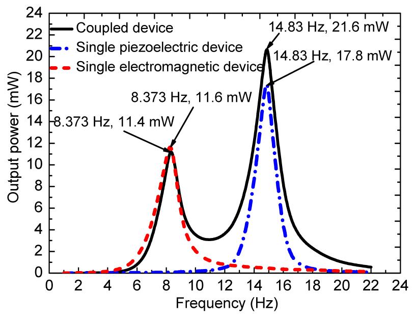
The optimal external resistances of the electromagnetic and piezoelectric systems are 1 kΩ and 178 kΩ, respectively. In the case of the input acceleration of 5 m/s2, the power output of the hybrid energy harvester and individual energy harvester are shown in Fig. 5.
Fig.5 Comparison of the single device and the coupled power output (the input acceleration equals 5 m/s2)
The piezoelectric-electromagnetic vibration energy harvester has two output peak frequencies. The peak frequency of the electromagnetic occurs at 8.373 Hz, while the peak frequency of the piezoelectric occurs at 14.83 Hz. So it has a considerable power output in the range of 6 to 20 Hz, which is three times the bandwidth of the stand-alone, single harvesting mode devices. Furthermore, it increases the efficiency of energy conversion and the power output. The two peak power outputs are 11.4 mW and 21.6 mW, respectively.
4. Finite element simulation and experiments
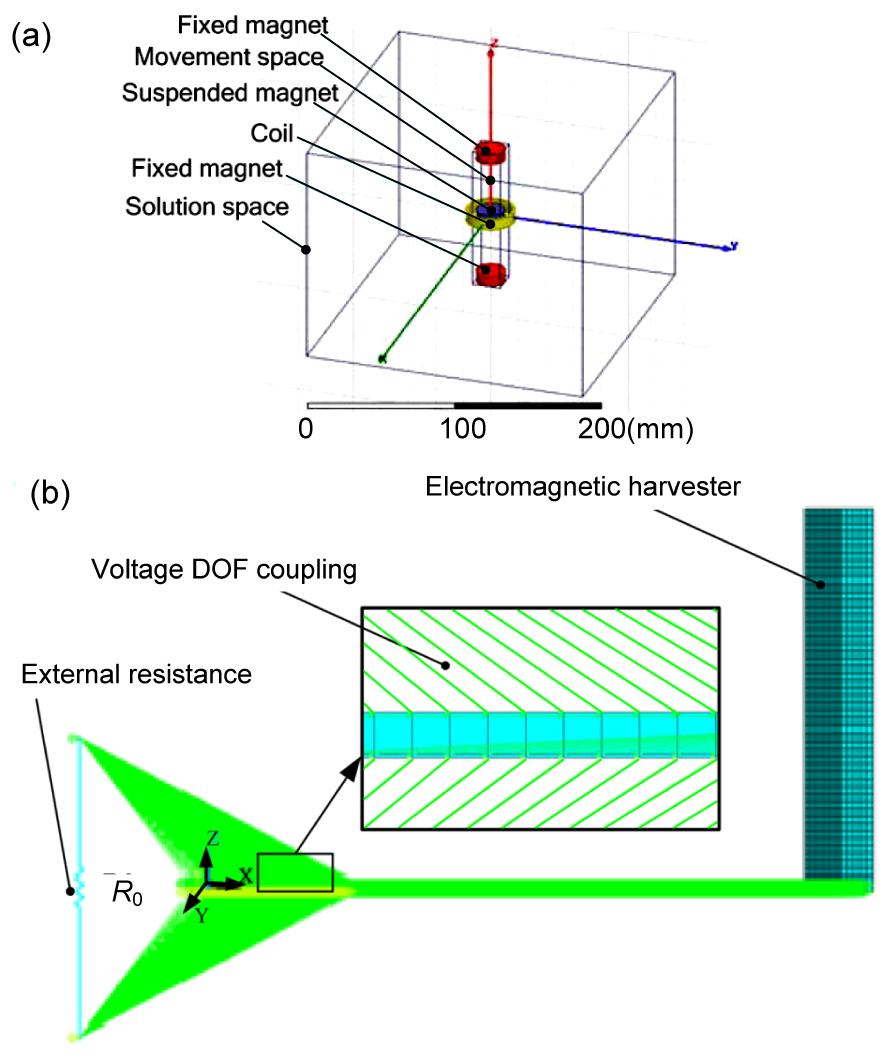
The model of the electromagnetic system was established using MAXWELL (Fig. 6a) and the model of the piezoelectric system was established in ANSYS (Fig. 6b). Fig. 7 shows the experimental system. Fig. 8 shows the comparison of the hybrid output powers obtained from the numerical simulation, the finite element simulation, and the experiments. The experimental results show that the peak power outputs of the hybrid harvester are 7.2 mW and 16.4 mW at the resonance frequencies of 8.5 Hz and 16 Hz, respectively. Compared to the previous studies (Shen et al., 2008; Torah et al., 2008; Yang and Tang, 2009), this hybrid harvester effectively broadens the frequency bandwidth. The average error rates of the peak frequency of the numerical analysis and finite element simulation to the experimental results are very small, but that of the power output are slightly larger. The reasons for these slightly high error rates are related to the following aspects:
Simplified models are used in the mathematical modeling.
Even though the multiple time scale method can solve the governing equation, finally, the solution is an approximate one.
Lateral force is ignored in the mathematical modeling. Lateral force increases the mechanical damping, so it can affect the finite element result and numerical result.
Fig.6 Finite element models of the electromagnetic system (a) and piezoelectricity system (b)
Fig.7 Experimental system
Fig.8 Comparison of the numerical, the finite element simulation, and the experimental results
5. Conclusions
In this paper, a new hybrid energy harvester using two power generation mechanisms (piezoelectric and electromagnetic) is presented. The theoretical power output models were developed based on the piezoelectric equation and the nonlinear theory. The experimental and finite element simulation results of this coupled device show a very good agreement with the numerical results of the developed mathematical model. It demonstrates that the theoretical model of the hybrid harvester is valid. The present work shows that the coupling of energy harvesting techniques is a simple and effective way to broaden the frequency bandwidth and increase the energy harvesting power output. Further, developing multiple power output peaks from different power generation mechanisms is a promising method to obtain an even better output effect.
[1] Beeby, S.P., Tudor, M.J., White, N.M., 2006. Energy harvesting vibration sources for microsystems applications. Measurement Science and Technology, 17(12):R175-R195.
[2] Challa, V.R., Prasad, M.G., Fisher, F.T., 2009. A coupled piezoelectric-electromagnetic energy harvesting technique for achieving increased power output through damping matching. Smart Materials and Structures, 18(9):095029
[3] Gonsalez, C.G., Franco, V.R., Brennan, M.J., 2010. Energy Harvesting Using Piezoelectric and Electromagnetic Transducers. , 9th Brazilian Conference on Dynamics, Control and Their Applications, Serra Negra, Brazil, 1166-1171. :1166-1171.
[4] MacCurdy, R.B., Reissman, T., Garcia, E., 2008. Energy Management of Multi-component Power Harvesting Systems, Proc. SPIE 6928, Active and Passive Smart Structures and Integrated Systems, San Diego, California, USA, 692809:692809
[5] Mann, B.P., Sims, N.D., 2009. Energy harvesting from the nonlinear oscillations of magnetic levitation. Journal of Sound and Vibration, 319(1-2):515-530.
[6] Mann, B.P., Owens, B.A., 2010. Investigations of a nonlinear energy harvester with a bistable potential well. Journal of Sound and Vibration, 329(9):1215-1226.
[8] Roundy, S., Wright, P.K., Rabaey, J.M., 2004. Energy Scavenging for Wireless Sensor Networks: with Special Focus on Vibrations, Springer, Kluwer Academic Publishers,:
[9] Shen, D., Park, J.H., Ajitsaria, J., Choe, S.Y., Wikle, H.C., Kim, D.J., 2008. The design, fabrication and evaluation of a MEMS PZT cantilever with an integrated Si proof mass for vibration energy harvesting. Journal of Micromechanics and Microengineering, 18(5):055017
[10] Stephen, N.G., 2006. On energy harvesting from ambient vibration. Journal of Sound and Vibration, 293(1-2):409-425.
[11] Tadesse, Y., Zhang, S.J., Priya, S., 2009. Multimodal energy harvesting system: piezoelectric and electromagnetic. Journal of Intelligent Material Systems and Structures, 20(5):625-632.
[12] Torah, R., Glynne-Jones, P., Tudor, M., O'Donnell, T., Roy, S., Beeby, S., 2008. Self-powered autonomous wireless sensor node using vibration energy harvesting. Measurement Science and Technology, 19(12):125202
[13] Wacharasindhu, T., Kwon, J.W., 2008. A micromachined energy harvester from a keyboard using combined electromagnetic and piezoelectric conversion. Journal of Micromechanics and Microengineering, 18(10):104016
[14] Wang, H.Y., Shan, X.B., Xie, T., 2012. An energy harvester combining a piezoelectric cantilever and a single degree of freedom elastic system. Journal of Zhejiang Universit-SCIENCE A (Applied Physics & Engineering), 13(7):526-537.
[15] Wang, P.H., Tao, K., Yang, Z.Q., Ding, G.F., 2013. Resin-bonded NdFeB micromagnets for integration into electromagnetic vibration energy harvesters. Journal of Zhejiang University-SCIENCE C (Computer & Electronics), 14(4):283-287.
[16] Williams, C.B., Yates, R.B., 1996. Analysis of a micro-electric generator for microsystems. Sensors and Actuators A: Physical, 52(1-3):8-11.
[17] Wischke, M., Masur, M., Woias, P., 2009. A Hybrid Generator for Vibration Energy Harvesting Applications. , Solid-State Sensors, Actuators and Microsystems Conference, IEEE, Denver, Colorado, USA, 521-524. :521-524.
[18] Yang, B., Kee, W.L., Lim, S.P., Lee, C.K., 2010. Hybrid energy harvester based on piezoelectric and electromagnetic mechanisms. Journal of Micro/Nanolithography, MEMS, and MOEMS, 9(2):023002
[19] Yang, Y., Tang, L., 2009. Equivalent circuit modeling of piezoelectric energy harvesters. Journal of Intelligent Material Systems and Structures, 20(18):2223-2235.
[20] Yuan, J.B., Xie, T., Shan, X.B., Chen, W.S., 2009. Resonant frequencies of a piezoelectric drum transducer. Journal of Zhejiang University-SCIENCE A, 10(9):1313-1319.
Open peer comments: Debate/Discuss/Question/Opinion


Open peer comments: Debate/Discuss/Question/Opinion
<1>