Affiliation(s):
1.
Department of Civil Engineering, Zhejiang University, Hangzhou 310027, China; moreAffiliation(s): 1.
Department of Civil Engineering, Zhejiang University, Hangzhou 310027, China; 2.
Department of Building Engineering, Tongji University, Shanghai 200092, China; less
Zhi Wang, Xian-yu Jin, Nan-guo Jin, Xiang-lin Gu, Chuan-qing Fu. Cover cracking model in reinforced concrete structures subject to rebar corrosion[J]. Journal of Zhejiang University Science A, 2014, 15(7): 496-507.
@article{title="Cover cracking model in reinforced concrete structures subject to rebar corrosion", author="Zhi Wang, Xian-yu Jin, Nan-guo Jin, Xiang-lin Gu, Chuan-qing Fu", journal="Journal of Zhejiang University Science A", volume="15", number="7", pages="496-507", year="2014", publisher="Zhejiang University Press & Springer", doi="10.1631/jzus.A1300393" }
%0 Journal Article %T Cover cracking model in reinforced concrete structures subject to rebar corrosion %A Zhi Wang %A Xian-yu Jin %A Nan-guo Jin %A Xiang-lin Gu %A Chuan-qing Fu %J Journal of Zhejiang University SCIENCE A %V 15 %N 7 %P 496-507 %@ 1673-565X %D 2014 %I Zhejiang University Press & Springer %DOI 10.1631/jzus.A1300393
TY - JOUR T1 - Cover cracking model in reinforced concrete structures subject to rebar corrosion A1 - Zhi Wang A1 - Xian-yu Jin A1 - Nan-guo Jin A1 - Xiang-lin Gu A1 - Chuan-qing Fu J0 - Journal of Zhejiang University Science A VL - 15 IS - 7 SP - 496 EP - 507 %@ 1673-565X Y1 - 2014 PB - Zhejiang University Press & Springer ER - DOI - 10.1631/jzus.A1300393
Abstract: A new cover cracking model is proposed for rebar corrosion. Rebar corrosion involves rust, which contributes to an expansive radial pressure at the concrete-steel interface and hoop tensile stresses in the surrounding concrete. Once the stress state exceeds a certain limit, anisotropic damage occurs. First, we establish an anisotropic damage model for concrete, which fully reflects the unilateral effect. Then an analytical model is proposed to calculate the displacement and the stress in a corroded reinforced concrete (RC) structural member based on that anisotropic damage. In this study, a concrete-rust-steel composite model is considered as a circular cylindrical concrete cover and a coaxial, uniformly-corroded, steel rebar, where the steel rebar and the mechanical properties of rust can be fully taken into account. At the same time, the influences of the steel-concrete interface pores and the cracks in concrete on the rust expansion pressure value are modeled. Finally, some experiments are made for comparison with the analytical results and good agreement indicated the proposed model could be used to predict both the variation of strain fields in structures during the corrosion process and the cover cracking time.
Darkslateblue:Affiliate; Royal Blue:Author; Turquoise:Article
Article Content
1. Introduction
Rebar corrosion with expansion of corrosion products leads to the cracking and even spalling of the covering concrete. Thus, reinforcement corrosion is regarded as the major cause of structural degradation in reinforced concrete (RC) structures (Bazant, 1979; Sanchez et al., 2010). In fact, when the cover concrete bears radial pressure caused by the expansion of the products of corrosion, the tension strain and damage are in the hoop direction (Coronelli, 2002; Melchers and Jeffrey, 2005). So an analysis of cover cracking should address the anisotropic damage characteristics of concrete under a multi-axial stress state (Grassl and Jirasek, 2006).
Originally, empirical models were proposed (Tepfers, 1979; Andrade et al., 1993; Molina et al., 1993; Gambarova and Rosati, 1996), but they failed to provide a physical explanation for cracking so further relevant works and analytical models were deployed (Bazant, 1979; Liu and Weyers, 1998; Pantazopoulou and Papoulia, 2001; Bhargava et al., 2005; 2006a; 2006b; Chernin et al., 2010; Shodja et al., 2010; Chernin and Val, 2011; Kiani and Shodja, 2011). These contributions improved our knowledge of the problem. However, some discrepancies between the predicted values from theoretical models and the observed data from the laboratory have been reported. These may be due to a lack of knowledge of the rate of the corrosion process, the mechanical properties of the corrosion rusts in corroded RC structures, the softening behavior of the concrete, or some other causes (Rabczuk et al., 2005; Wong et al., 2010).
In this paper, an analytical anisotropic damage model is proposed for predicting the time of cracking of cover concrete and analyzing the factors influencing the corrosion in RC structures. Based on (Shodja et al., 2010), the proposed model incorporates: (1) a constitution equation involving anisotropic damage coupled elasticity, (2) the contribution of elasticity of rebar and corrosion rusts, and (3) the consideration of rusts filling interface pores and cracks. The predicted values by the analytical model are compared with the available experimental data and the parameters of the model are investigated to obtain their effect on cover cracking. For the convenience of readers, it is worth summarizing the differences between Shodja et al. (2010)’s model and our model, which are given as follows: (1) in his paper, influence of the steel-concrete interface pores was not considered, but in our paper, it is fully considered, and this factor is very important to the corrosion problem; (2) in his paper, the calculation method was gradient reproducing kernel particle method (GRKPM), which was essentially a boundary element method. In our paper, the calculation procedure has been improved and made more convenient; (3) in addition, we validate our proposed model experimentally, and the factors involved are analyzed independently to obtain their effect on displacement and stress fields.
2. Analysis for reinforcement corrosion
When a rebar corrodes it produces corrosion products and those will expand. Because corrosion rust takes a greater volume than the virgin steel bars and cannot expand freely due to the restraint of the concrete cover, corrosion rust brings expansive force to the concrete cover. As the expansive force increases, the concrete cover suffers anisotropic damage under multi-axial stresses sufficient to produce micro-cracks near a rebar (Fig. 1d).
Fig.1 (a) Reinforced concrete structural member; (b) A rebar with radius Rst embedded in concrete with cover thickness C; (c) Illustration for concrete-rust-steel composite material; (d) Crack propagation in concrete for reinforcement corrosion
For a real RC structural member (Fig. 1a), we consider a circular cylindrical reinforcement concrete model, where a rebar with initial radius Rst is embedded in concrete with cover thickness C, and Rcon=Rst+C (Fig. 1b). The reinforcement corrosion is such that a reduction of the radius of the steel rebar radius takes place simultaneously on the surface of the rebar along a considerable length. Due to uniform corrosion on the rebar surface, the rebar radius reduces to Rcb, and a thin layer of the rust with a thickness of Rr−Rcb surrounds the corroded rebar (Fig. 1c).
2.1. Description for volume expansion
Here, Vr and Vs are defined as the volumes of the generated rust and the consumed steel, respectively. In this work, a model proposed in (Liu and Weyers, 1998) is used to determine Vr and Vs as follows:
,
,
where t is the time, ρst is the steel density, kg/m3, rm is the ratio of the molecular mass of iron to the corrosion products, α is the ratio of the density of steel to the density of the corrosion products (Liu and Weyers, 1998), and icorr is the corrosion current density.
In general, the concrete cracking process by corrosion includes three periods (Liu and Weyers, 1998): expansion with no stress stage, expansion with a stress initiation stage, and expansion with a concrete cracking stage. In the first stage, corrosion rusts fill the porous voids around the concrete and steel interface, and the rusts expand freely without creating any stresses in the surrounding concrete. With further increase of corrosion an expansive pressure is produced as the corrosion forms on the virgin steel bars and consequently displacement of the interface between steel and concrete are generated. At the third stage, the pressure is large enough to create cracks in the concrete.
From the above analysis, the total rust volume Vr can be approximately taken as the summation of three components. The first part Vpore is filling the interface pores between steel and concrete. The rust fills the pores first. So the interface thickness tpore and porosity pvp (Bertolini, 2008) are the key parameters. Here an effective interface thickness tp was introduced, which is equal to the pore void as
.
The second part Vpress is filling the space created by pressure and the consumption of steel. The last Vcrack is occupation of the cracks. This can be expressed as
where φ is the ratio of the occupied space to the total volume of the vacant spaces of micro-cracks, tp is about 15 μm (Bertolini, 2008), and H(x) is the Heaviside function and CWO is the crack-width openings which can be calculated by
,
leading to
,
,
,
where ucon(r) denotes the displacement of concrete at radius r of a circular cylinder, εθ is the hoop strain, is the tensile limit strain and tr is the width of rust. For brevity, all of the radius variables are depicted in Fig. 2.
Fig.2 Schematic of steel rebar corrosion x: corrosion depth; Rst: initial radius of the rebar; Rcb: radius of the corroded rebar; Rf: rust front for freely expanding; Rr: rust front for actual expanding
2.2. Description for rust properties
The properties of corrosion products are very important in the process of corrosion expansion (Molina et al., 1993), so they should be properly considered in corrosion model. Molina et al. (1993) assumed that rusts are linear isotropic materials. Pantazopoulou and Papoulia (2001) supposed that the rust and steel rebar are rigid. Recently, Bhargava et al. (2005) considered that rusts and the steel rebar exhibit the same elastic behavior. Lundgren (2002; 2005) showed that rusts perform like granular materials and assumed a power law constitution relation for them. Recently, Ouglova et al. (2006) confirmed the conclusion of Lundgren (2002) for the performance of corrosion products, which can be expressed as ,
where εcorr denotes the compressive strain of the corrosion products, αcorr is the corresponding radial compressive stress, and kcorr and ncorr are empirical coefficients. Note that Lundgren (2002) extracted kcorr≈7×10⁹ Pa and ncorr≈7 from the experiments of other researchers (Alsulaimani et al., 1990; Andrade et al., 1993).
2.3. Description of concrete properties
The adopted stress-strain relationship for concrete under tension and compression is presented in Fig. 3. When concrete is subjected to compression, the strain-stress relation is a curve with the initial elasticity modulus E0 ((MPa)), where fc′ (MPa) is the uniaxial compression strength of concrete.
Fig.3 Curves of stress-strain relationship for concrete
The radial compressive and the hoop tensile damage indices Dr and Dθ can be expressed as Eq. (10) and Eq. (11), respectively.
,
where (MPa), fct,res=0.15fct (MPa), (MPa), εcr=0.0003, ε1=fct/E0, and εu=0.002.
We mention that the radial damaged modulus (Er(Dr), Er(Dr)=(1−Dr)E0) and the hoop damaged modulus (Eθ(Dθ), Eθ(Dθ)=(1−Dθ)E0) are respectively defined by the secant slopes of the compressive and tensile stress-strain curves (Fig. 3).
3. Analytical solution of the problem
3.1. Mathematical modeling
Some important assumptions are made in this study as follows: (1) reinforcement corrodes uniformly; (2) the amount of total corrosion products, some part filling the interface pores and penetrating into the micro-cracks, can all be calculated throughout the corrosion process.
Based on the above assumptions, the governing equation of the concrete-rust-steel composite can be derived as
.
The elastic strain-displacement relation is
and the stress-strain relations are expressed as
For the plane stress case, the parameters in Eq. (14) can be defined as
Moreover, for the plane strain case, the parameters in Eq. (14) can be defined as
where vrθ(D), vθr(D), vrz(D), vzr(D), vθz(D), and vzθ(D) are the damaged Poisson’s ratios. They are all the function of the anisotropic damage matrix D.
By substituting Eqs. (13) and (14) into Eq. (12) and considering the symmetry of Fθr(D)=Fθr(D), the governing Eq. (12) can be written as
,
where depends on the plane stress or the plane strain problem.
The damage to concrete caused by hoop and radial stresses is anisotropic. There is a difference in the extent of damage in different positions. Even in the same position, the damage is different in the hoop and radial directions of the specimen. So cracked concrete caused by rebar corrosion is a heterogeneous medium. This point is considered by the parameter Ψ. Based on above analysis, the displacement solution of Eq. (17) can be obtained as
,
where A and B are parameters determined by boundary condition. The strain and stress components are expressed as
and Dependency of Ψ on the parameters D and r brings complexity to finding a closed form solution for Eq. (14). In this study, the concrete medium is divided into N layers, so that the parameter Ψ is constant within each layer (Fig. 4). Therefore,
where
Fig.4 N layers of concrete medium
The properties of steel reads, Er=Ez=Eθ=Est, vrz=vrθ=vθz=vst, and thus Ψ=1, in which Est and vst are the elastic modulus and Poisson’s ratio of the rebar, respectively. Therefore, the displacement and stress of steel rebar can be expressed by
3.2. Boundary condition
The radial component of the displacement and stress across the boundary is continuous between the ith and the (i+1)th layer and can be expressed as
,
where ri is the radius of the outer interface of ith layer.
For the stress-free state of the surface in the concrete cover, we obtain:
.
When rebar and inner concrete causes a displacement discontinuity due to corrosion rust, it yields
The nonlinear expression of the parameter tr, and the nonlinear relation between εcorr and σcorr lead to a nonlinear boundary value problem. Assuming tr≪Rst, it is reasonable to neglect the thickness of the rust, and it yields
.
Based on the above analysis Eqs. (28)–(31) can be written in the form
,
where
and the elements of the coefficient matrix are given in Appendix A.
We mention that fcorr is nonlinear, and hence, Eq. (33) is a nonlinear equation set. In the following, an effective solution is provided.
3.3. Computing algorithm for the model
For brevity, the computing algorithm for Eq. (33) is introduced as follows:
Input the steel-rust-concrete material parameters and other parameters, such as elastic modulus, Poisson’s ratio, and corrosion electric current density;
Initialize the conditions of the problem: set t=0, εcorr=0, Rcr=Rst, and xold=0;
Determine Vr(t) and Vs(t) from Eq. (1) and Eq. (2), and Rcb from Eq. (8);
Determine Kold and fold at xold;
Get xnew by using Newton’s iteration method, with Kold and fold;
Obtain the damage matrix D and the materials properties based on xnew;
If met convergence, next step; if not, go back to step 4;
Set t=t+Δt, and get the required outputs. Check the required cover cracking time is reached or not. If it is not, go back to step 3.
In the end, the program was coded in MATLAB 7.11 to implement the algorithm.
4. Results and discussion
4.1. Strain field during corroded process
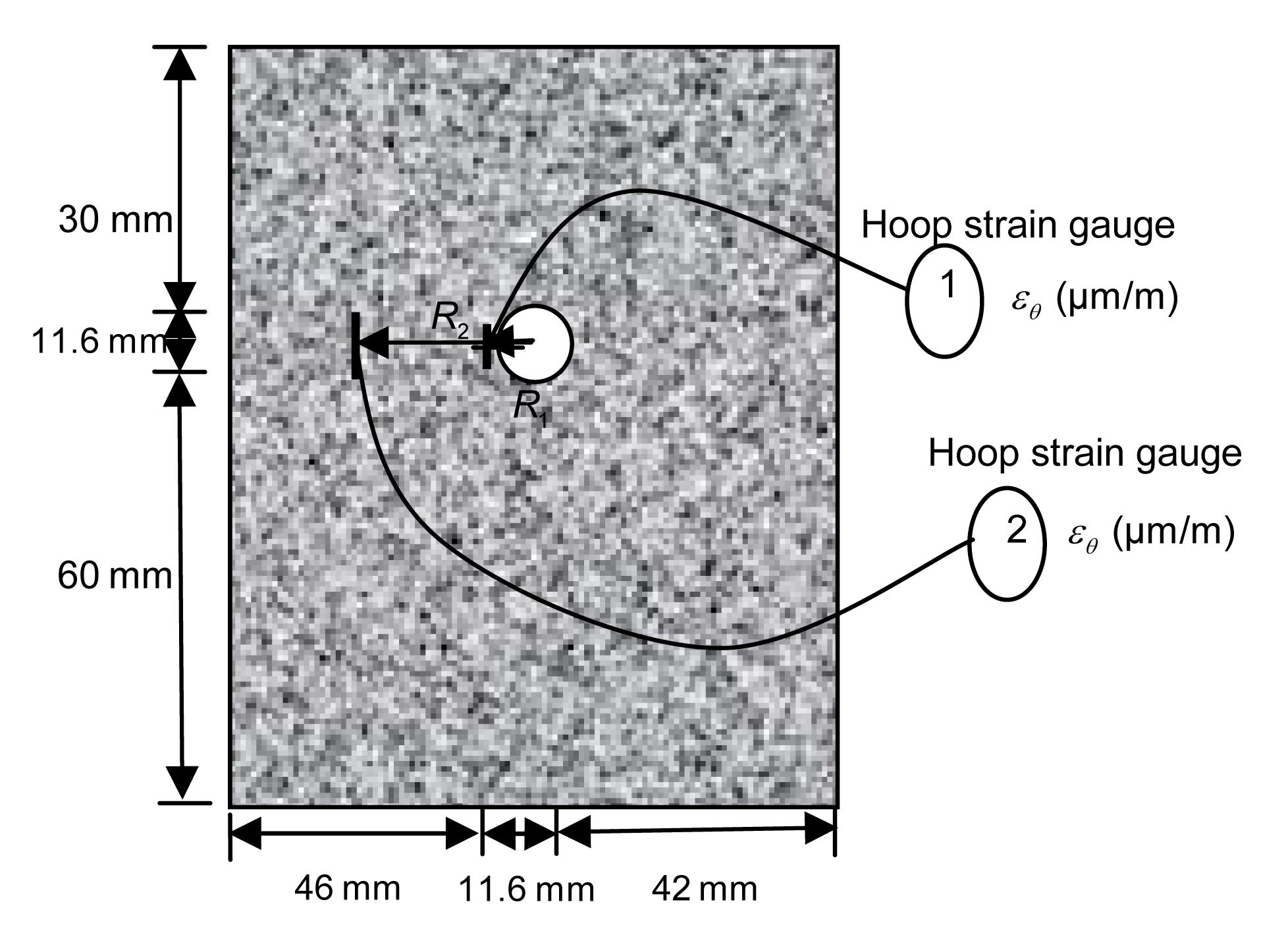
To test the proposed model, a current accelerated corrosion test was done. The dimension of the specimen was about 100 mm×100 mm×100 mm. The concrete was cast with Portland cement, crushed coarse aggregate, sand, and tap water. The mass density of the cement was 330 kg/m3 and w/c=0.5. A longitudinal rebar was embedded inside the specimen (Fig. 5).
Fig.5 Specimen of the accelerated test
The parameters adopted in the calculation were vcon=0.17, Rst=0.0058 m, Est=2×10¹¹ Pa, vst=0.3, kcorr=7×10⁹ Pa, ncorr=7, icorr=4.5 A/m2, rm=0.622, α=2.09, tp=0, φ=0.1, and N=5.
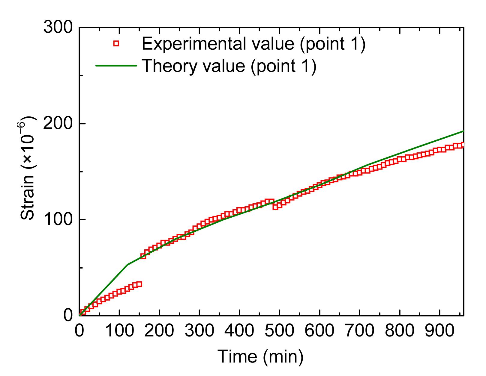
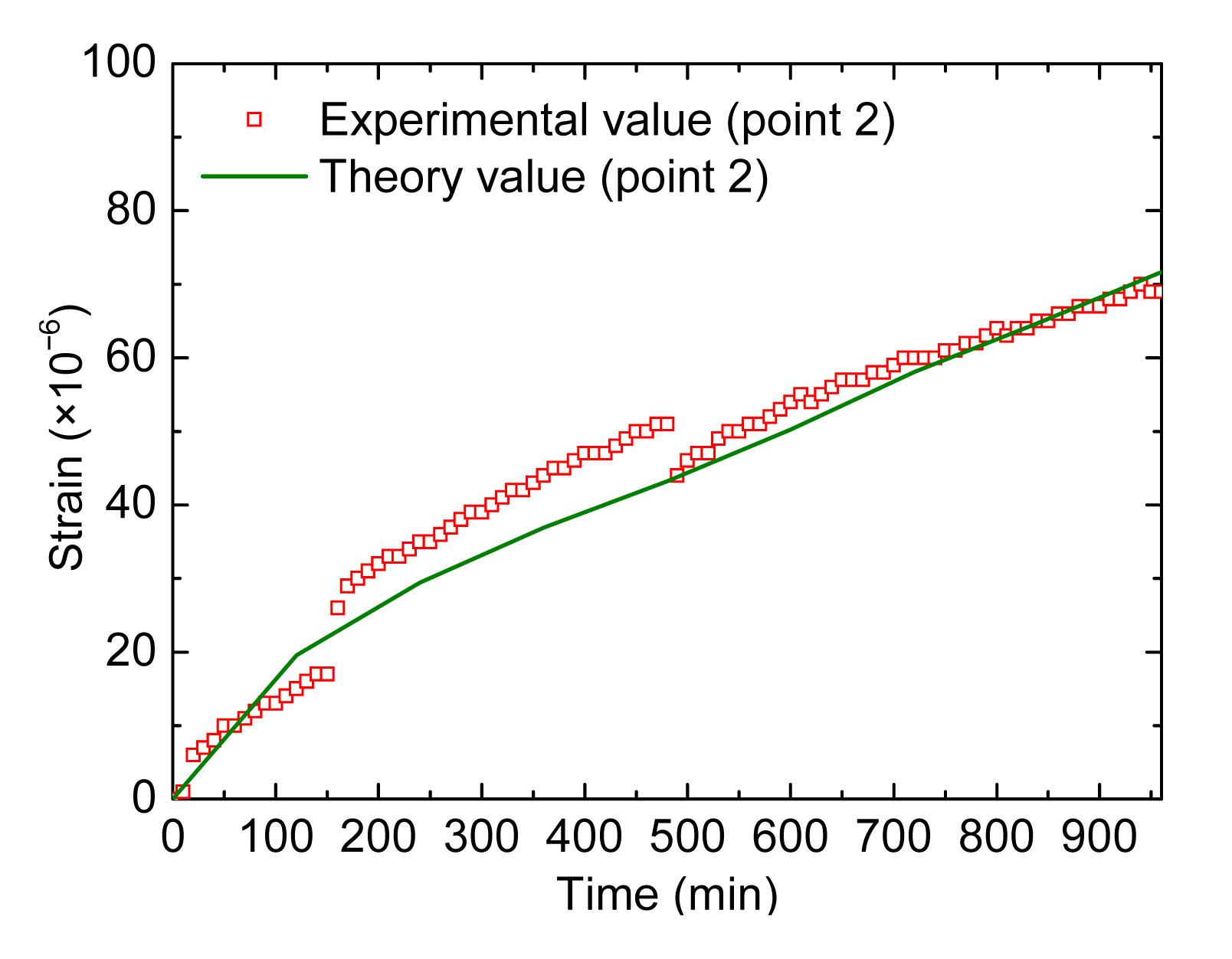
A group of three strain gauges was posted at a fixed radius, and there were two groups. The experiment data were acquired every 10 min. The data were averaged in every group. The hoop strain predicted by theory and the corresponding average experimental data are shown in Fig. 6 and Fig. 7.
Fig.6 Comparison between experimental and theory values at point 1
Fig.7 Comparison between experimental and theory values at point 2
From the above results, it can be seen that the predicted values match the experimental data well, which shows that the model is effective in calculating the strain and stress values during the corrosion process.
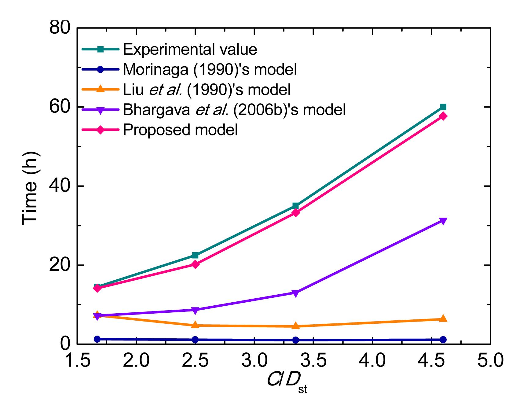
4.2. Time of cover cracking
For checking the correctness of the proposed analytical solution, the predicted values by this model were compared with experimental results (Rasheeduzzafar et al., 1992) and other models (Table 1 and Table 2).
Table 1
Experimental values in (Rasheeduzzafar et al., 1992)
Specimen
Dst (m)
C (m)
fc′ (MPa)
Icorr (A/m2)
Tcr (h)
S1
0.0190
0.03173
35.4
30
14.5
S2
0.0127
0.03175
35.4
30
22.5
S3
0.0095
0.03183
35.4
30
35.0
S4
0.0080
0.03680
35.4
30
60.0
Table 2
Comparison of cover cracking time between proposed model and other models (h)
Fig. 8 shows that the predicted results for the time of cover cracking with different models vary a lot, but the results with the proposed model match the experimental values well because the rust property, interface, filling effect, and properties of concrete have been fully and correctly taken into account.
Fig.8 Time to cover cracking with various ratios of cover thickness to steel diameter (C/Dst)
4.3. Effect of porous zone on the corrosion-induced strain field
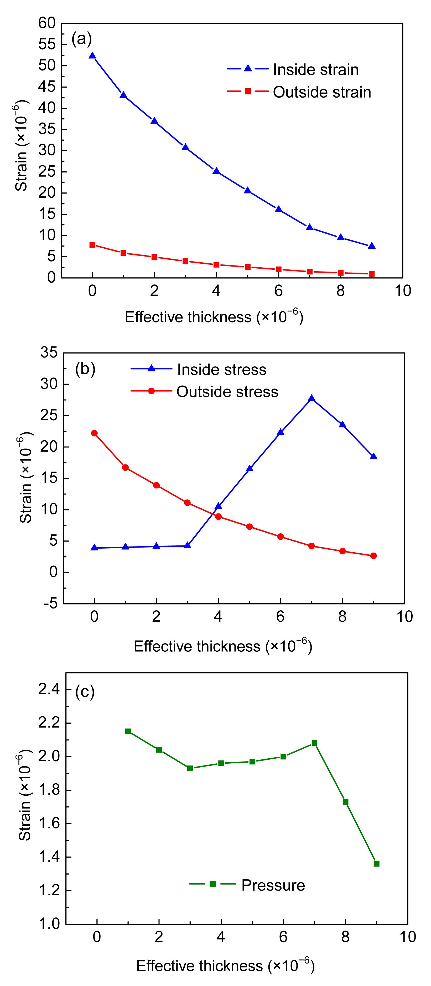
To examine the rust filling in the interface between steel and concrete, the program coded in MATLAB 7.11 was run to determine the relationship between strain and effective interface thickness (Fig. 9a), the relationship between stress and effective interface thickness (Fig. 9b), and the relationship between pressure and effective interface thickness (Fig. 9c).
Fig.9 Rust filling effect of effective interface thickness (a) Relationship between hoop strain and effective thickness; (b) Relationship between hoop stress and effective thickness; (c) Relationship between internal pressure and effective thickness
The parameters adopted in the calculation were C=0.0368 m, fc′=35.4 MPa, vcon=0.17, Rst=0.004 m, Est=2×10¹¹ Pa, vst=0.3, kcorr=7×10⁹ Pa, ncorr=7, icorr=30 A/m2, t=4×3600 s, rm=0.622, α=2.09, φ=0, and N=5.
Fig. 9a shows the filling effect at the interface. As the effective interface thickness increases, the hoop strains of both inner concrete and outer concrete decrease.
Fig. 9b shows when the effective interface thickness increases, the outer hoop stress decreases, but the inner hoop stress fluctuates. When the effective thickness is larger than 8×10⁻⁶ m, the inner concrete will not be damaged and perform well. When the effective thickness is smaller than 8×10⁻⁶ m but larger than 3×10⁻⁶ m, the hoop strain of the inner concrete will be large enough to cause damage in it. So with the effective interface thickness decreasing within this range, the inner concrete will damage and the stress in it will decrease. However, it does not always lead to the damage of outer concrete, so the outer hoop stress may increase. When the effective thickness is smaller than 3×10⁻⁶ m, the inner concrete will be severely damaged, and the inner hoop stress level will remain low.
Fig. 9c shows the pressure as the function of effective thickness. The analysis is the same as for the hoop stress of the inner concrete. When the effective thickness is larger than 8×10⁻⁶ m, the pressure will increase with the increase of effective thickness. When the effective thickness is smaller than 8×10⁻⁶ m but larger than 3×10⁻⁶ m, the damage will increase with the decrease of effective interface thickness. At the same time, the filling space will decrease and the pressure will also decrease. When the effective thickness is smaller than 3×10⁻⁶ m, the inner concrete will be severely damaged, and the pressure will increase accordingly.
Recently, some authors have used pressure as a measure of the corrosion level. From the above analysis, it can be seen that pressure is not a good indicator for describing the degree of damage of cover concrete. However, the inner hoop strain or outer hoop strain can be used as good indicators. Therefore, in the following part of this paper, the inner hoop strain and outer hoop strain are selected as the key parameters.
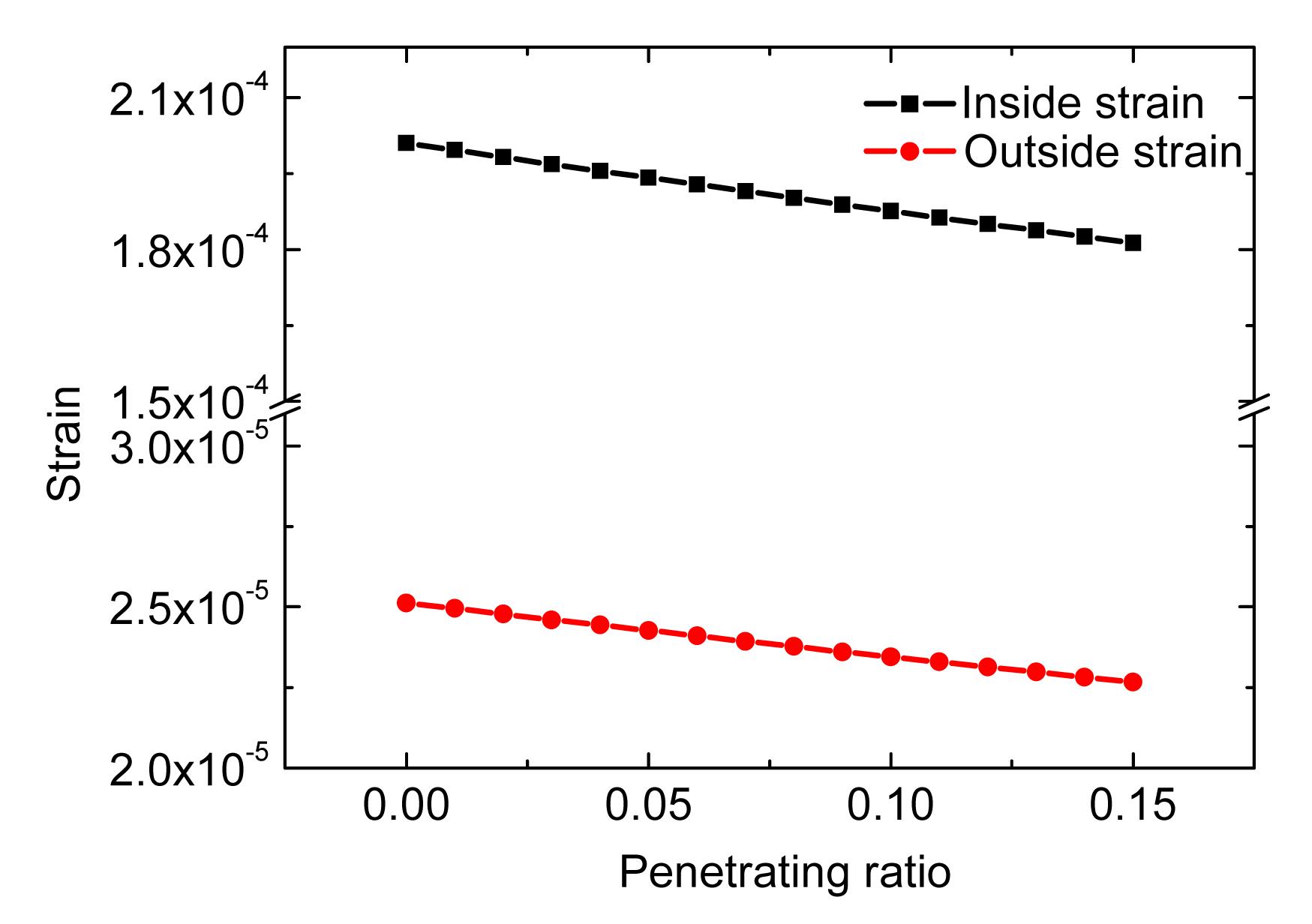
4.4. Effect of rust penetrating into cracks on the corrosion-induced strain field
To examine the rust penetrating into crack induced by corrosion, the program coded in MATLAB 7.11 was run to get the relation between the inner and outer hoop strains and the penetrating ratio (Fig. 10).
Fig.10 Relationship between hoop strains and penetrating ratio
The parameters adopted in the calculation were C=0.0368 m, fc′=35.4 MPa, vcon=0.17, Rst=0.004 m, Est=2×10¹¹ Pa, vst=0.3, kcorr=7×10⁹ Pa, ncorr=7, icorr=30 A/m2, t=4×3600 s, rm=0.622, α=2.09, tp=0, and N=5.
Fig. 10 shows that the hoop strains decrease linearly with the increase of the penetrating ratio.
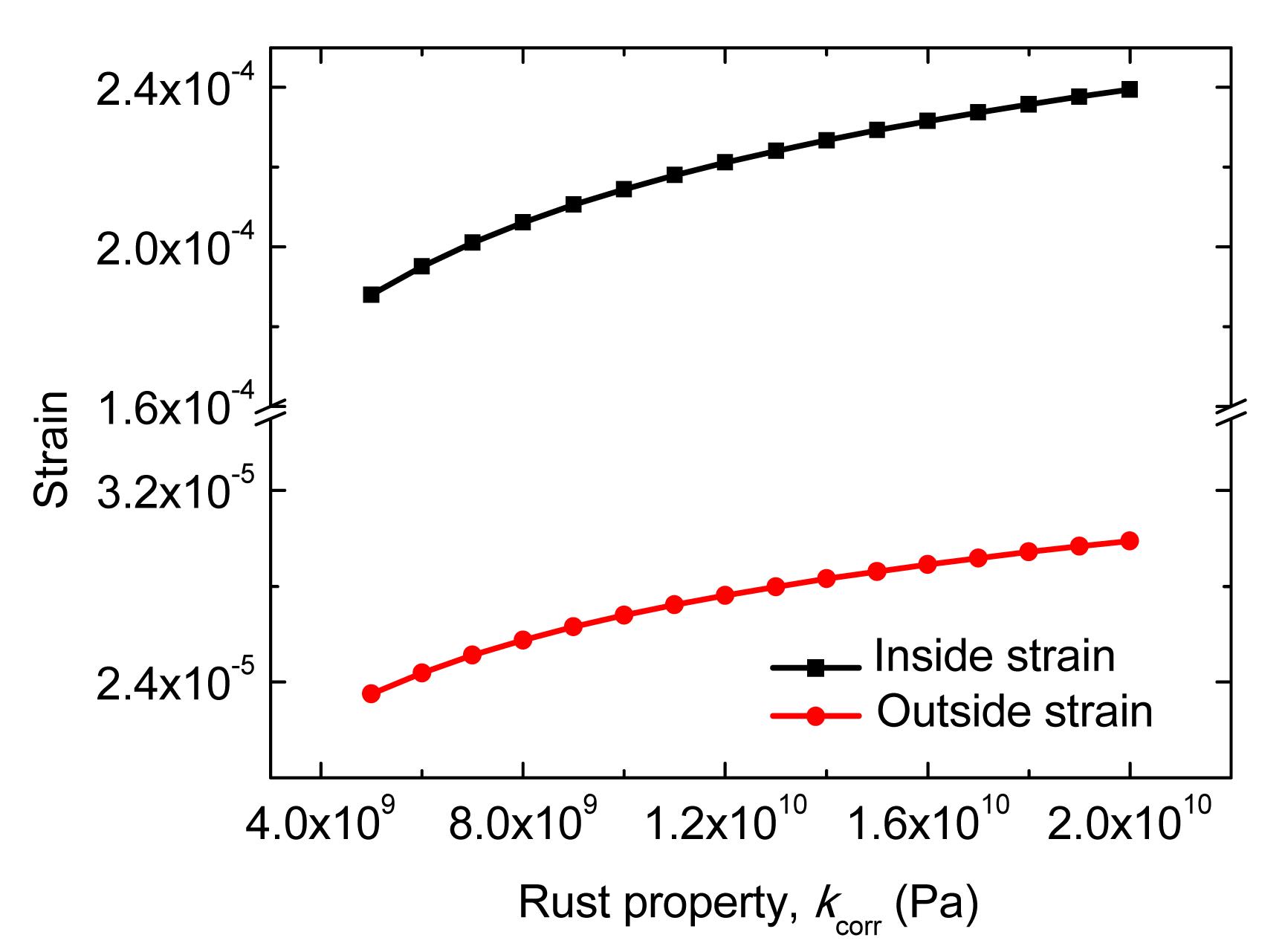
4.5. Effect of rust modulus on the corrosion-induced strain field
To examine the influence of the rust modulus, the program coded in MATLAB 7.11 was run to get the relationship between the inner and outer hoop strains and the rust modulus (Fig. 11).
Fig.11 Relationship between hoop strains and rust property
The parameters adopted in the calculation were C=0.0368 m, fc′=35.4 MPa, vcon=0.17, Rst=0.004 m, Est=2×10¹¹ Pa, vst=0.3, ncorr=7, icorr=30 A/m2, t=4×3600 s, rm=0.622, α=2.09, φ=0, tp=0, and N=5.
Fig. 11 shows that the hoop strains increase with the increase of the rust modulus.
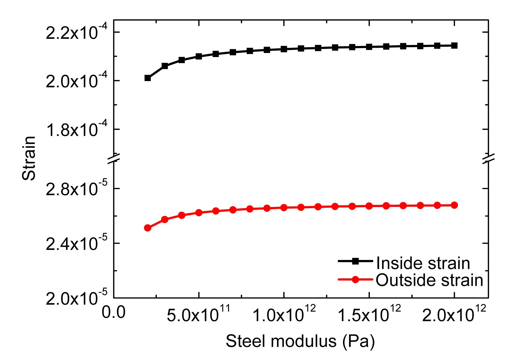
4.6. Effect of steel modulus on the corrosion-induced strain field
To examine the effect of the steel modulus, the program coded in MATLAB 7.11 was run to get the relationship between inner and outer hoop strains and the steel modulus (Fig. 12).
Fig.12 Relationship between hoop strains and steel modulus
The parameters adopted in the calculation were C=0.0368 m, fc′=35.4 MPa, vcon=0.17, Rst=0.004 m, vst=0.3, kcorr=7×10⁹ Pa, ncorr=7, icorr=30 A/m2, t=4×3600 s, rm=0.622, α=2.09, φ=0, tp=0, and N=5.
Fig.12 shows that the hoop strains increase nonlinearly with the increase of the steel modulus.
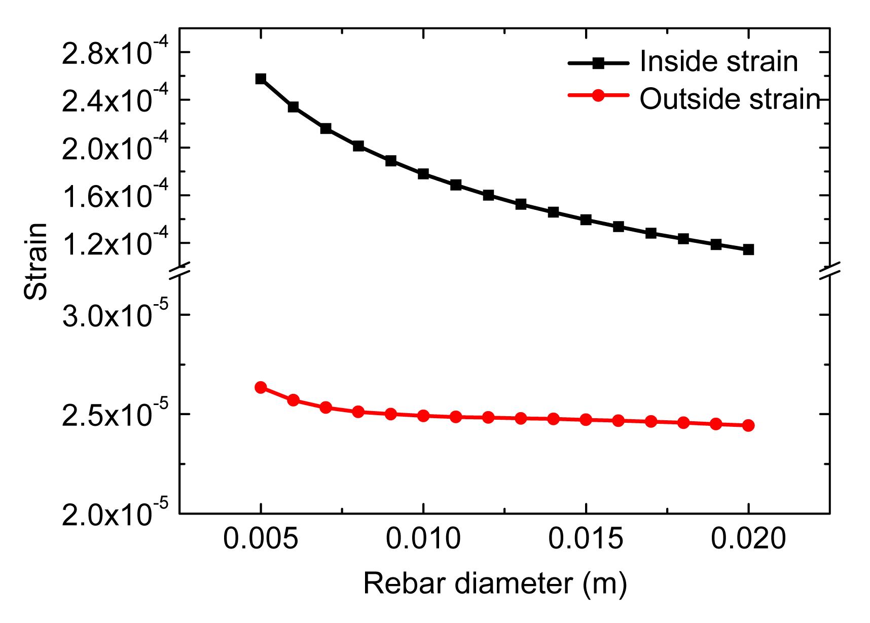
4.7. Effect of rebar diameter on the corrosion-induced strain field
For investigating the effect of rebar diameter on the strain, the program coded in MATLAB 7.11 was run to get the relationship between the inner and outer hoop strains and the diameter of the steel bar (Fig. 13).
Fig.13 Relationship between hoop strains and rebar diameter
The parameters adopted in the calculation were C=0.0368 m, fc′=35.4 MPa, vcon=0.17, Est=2×10¹¹ Pa, vst=0.3, kcorr=7×10⁹ Pa, ncorr=7, icorr=30 A/m2, t=4×3600 s, rm=0.622, α=2.09, φ=0, tp=0, and N=5.
Fig. 13 shows that the hoop strains decrease nonlinearly with the increase of the rebar diameter. Under the same influences, a steel bar of larger diameter produces smaller free rust expansion thickness compared with a bar of smaller diameter.
4.8. Effect of concrete cover thickness on the corrosion-induced strain field
To investigate the effect of cover thickness on the strain, the program coded in MATLAB 7.11 was run to get the relationship between the inner and outer hoop strains and the cover thickness (Fig. 14).
Fig.14 Relationship between hoop strains and cover thickness
The parameters adopted in the calculation were fc′=35.4 MPa, vcon=0.17, Rst=0.004 m, Est=2×10¹¹ Pa, vst=0.3, kcorr=7×10⁹ Pa, ncorr=7, icorr=30 A/m2, t=4×3600 s, rm=0.622, α=2.09, φ=0, tp=0, and N=5.
Fig. 14 shows that the hoop strains decrease nonlinearly with the increase of cover thickness.
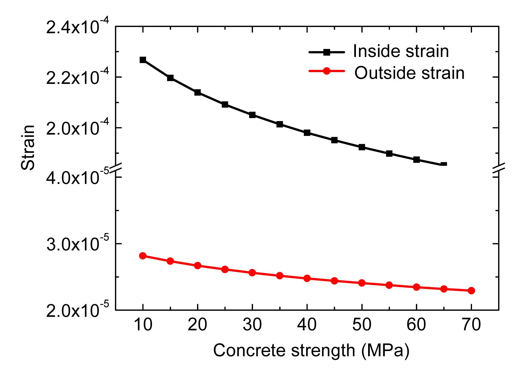
4.9. Effect of concrete strength on the corrosion-induced strain field
To examine the effect of concrete strength on the strains, the program coded in MATLAB 7.11 was run to get the relationship between the inner and outer hoop strains and concrete strength (Fig. 15).
Fig.15 Relationship between the inner and outer hoop strains and concrete strength
The parameters adopted in the calculation were C=0.0368 m, vcon=0.17, Rst=0.004 m, Est=2×10¹¹ Pa, vst=0.3, kcorr=7×10⁹ Pa, ncorr=7, icorr=30 A/m2, t=4×3600 s, rm=0.622, α=2.09, φ=0, tp=0, and N=5.
Fig. 15 shows that the hoop strains decrease nonlinearly with the increase of concrete strength.
5. Conclusions
A new rebar corrosion model was developed to determine the mechanical fields in RC structures, and the proposed model was used to predict the cracking time of the concrete cover. In this study, we considered a concrete-rust-steel composite consisting of a circular cylindrical concrete cover and a coaxial uniformly corroded steel bar, where the rust and steel rebar mechanical properties could be fully taken into account. At the same time, the influences of the steel-concrete interface pore and cracks in concrete on the rust expansion pressure value were satisfactorily modelled. The proposed model and experiment values show that: (1) when the crack occurs, the corrosion rust will penetrate into the crack, and the increasing velocity of hoop strain will decrease; (2) when the type and diameter of steel, and strength of concrete are chosen, the risk of cover cracking decreases with increasing the ratio of cover thickness to steel diameter (C/Dst).
[1] Alsulaimani, G.J., Kaleemullah, M., Basunbul, I.A., 1990. Rasheeduzzafar. Influence of corrosion and cracking on bond behavior and strength of reinforced-concrete members. ACI Structural Journal, 87(2):220-231.
[2] Andrade, C., Alonso, C., Molina, F.J., 1993. Cover cracking as a function of bar corrosion. 1. Experimental test. Materials and Structures, 26(8):453-464.
[3] Bazant, Z.P., 1979. Physical model for steel corrosion in concrete sea structures-application. Journal of the Structural Division, ASCE, 105(6):1155-1166.
[4] Bertolini, L., 2008. Steel corrosion and service life of reinforced concrete structures. Structure and Infrastructure Engineering, 4(2):123-137.
[5] Bhargava, K., Ghosh, A.K., Mori, Y., 2005. Modeling of time to corrosion-induced cover cracking in reinforced concrete structures. Cement and Concrete Research, 35(11):2203-2218.
[6] Bhargava, K., Ghosh, A.K., Mori, Y., 2006. Analytical model for time to cover cracking in RC structures due to rebar corrosion. Nuclear Engineering and Design, 236(11):1123-1139.
[7] Bhargava, K., Ghosh, A.K., Mori, Y., 2006. Model for cover cracking due to rebar corrosion in RC structures. Engineering Structures, 28(8):1093-1109.
[8] Chernin, L., Val, D.V., 2011. Prediction of corrosion-induced cover cracking in reinforced concrete structures. Construction and Building Materials, 25(4):1854-1869.
[9] Chernin, L., Val, D.V., Volokh, K.Y., 2010. Analytical modelling of concrete cover cracking caused by corrosion of reinforcement. Materials and Structures, 43(4):543-556.
[10] Coronelli, D., 2002. Corrosion cracking and bond strength modeling for corroded bars in reinforced concrete. ACI Structural Journal, 99(3):267-276.
[11] Gambarova, P.G., Rosati, G., 1996. Bond and splitting in reinforced concrete: test results on bar pull-out. Materials and Structures, 29(5):267-276.
[12] Grassl, P., Jirasek, M., 2006. Damage-plastic model for concrete failure. International Journal of Solids and Structures, 43(22-23):7166-7196.
[13] Kiani, K., Shodja, H.M., 2011. Prediction of the penetrated rust into the microcracks of concrete caused by reinforcement corrosion. Applied Mathematical Modelling, 35(5):2529-2543.
[14] Liu, Y.P., Weyers, R.E., 1998. Modeling the time-to-corrosion cracking in chloride contaminated reinforced concrete structures. ACI Materials Journal, 95(6):675-681.
[15] Lundgren, K., 2002. Modelling the effect of corrosion on bond in reinforced concrete. Magazine of Concrete Research, 54(3):165-173.
[16] Lundgren, K., 2005. Bond between ribbed bars and concrete. Part 2: the effect of corrosion. Magazine of Concrete Research, 57(7):383-395.
[17] Melchers, R.E., Jeffrey, R., 2005. Early corrosion of mild steel in seawater. Corrosion Science, 47(7):1678-1693.
[18] Molina, F.J., Alonso, C., Andrade, C., 1993. Cover cracking as a function of rebar corrosion. 2. Numerical-model. Materials and Structures, 26(9):532-548.
[19] Morinaga, S., 1990. Prediction of service lives of reinforced concrete buildings based on rate of corrosion of reinforcing steel. , Proceedings of the 5th International Conference on Durability of Building Materials and Components, Brighton, UK, 5-16. :5-16.
[20] Ouglova, A., Berthaud, Y., Francois, M., 2006. Mechanical properties of an iron oxide formed by corrosion in reinforced concrete structures. Corrosion Science, 48(12):3988-4000.
[21] Pantazopoulou, S.J., Papoulia, K.D., 2001. Modeling cover-cracking due to reinforcement corrosion in RC structures. Journal of Engineering Mechanics-ASCE, 127(4):342-351.
[22] Rabczuk, T., Akkermann, J., Eibl, J., 2005. A numerical model for reinforced concrete structures. International Journal of Solids and Structures, 42(5-6):1327-1354.
[23] Rasheeduzzafar, S.S., Al-Saadoun, A.S., Al-Gahtani, ., 1992. Corrosion cracking in relation to bar diameter, cover, and concrete quality. Journal of Materials in Civil Engineering, 4(4):327-342.
[24] Sanchez, P.J., Huespe, A.E., Oliver, J., 2010. Mesoscopic model to simulate the mechanical behavior of reinforced concrete members affected by corrosion. International Journal of Solids and Structures, 47(5):559-570.
[25] Shodja, H.M., Kiani, K., Hashemian, A., 2010. A model for the evolution of concrete deterioration due to reinforcement corrosion. Mathematical and Computer Modelling, 52(9-10):1403-1422.
[26] Tepfers, R., 1979. Cracking of concrete cover along anchored deformed reinforcing bars. Magazine of Concrete Research, 31(106):3-12.
[27] Wong, H.S., Zhao, Y.X., Karimi, A.R., 2010. On the penetration of corrosion products from reinforcing steel into concrete due to chloride-induced corrosion. Corrosion Science, 52(7):2469-2480.
Open peer comments: Debate/Discuss/Question/Opinion


Open peer comments: Debate/Discuss/Question/Opinion
<1>