Francesca Curà, Andrea Mura. Analysis of a load application point in spline coupling teeth[J]. Journal of Zhejiang University Science A, 2014, 15(4): 302-308.
@article{title="Analysis of a load application point in spline coupling teeth", author="Francesca Curà, Andrea Mura", journal="Journal of Zhejiang University Science A", volume="15", number="4", pages="302-308", year="2014", publisher="Zhejiang University Press & Springer", doi="10.1631/jzus.A1300323" }
%0 Journal Article %T Analysis of a load application point in spline coupling teeth %A Francesca Curà %A Andrea Mura %J Journal of Zhejiang University SCIENCE A %V 15 %N 4 %P 302-308 %@ 1673-565X %D 2014 %I Zhejiang University Press & Springer %DOI 10.1631/jzus.A1300323
TY - JOUR T1 - Analysis of a load application point in spline coupling teeth A1 - Francesca Curà A1 - Andrea Mura J0 - Journal of Zhejiang University Science A VL - 15 IS - 4 SP - 302 EP - 308 %@ 1673-565X Y1 - 2014 PB - Zhejiang University Press & Springer ER - DOI - 10.1631/jzus.A1300323
Abstract: The objective of this paper is to investigate the position of the resultant force in involute spline coupling teeth due to the contact pressure distribution for both ideal and misaligned conditions. In general, spline coupling teeth are in contact all along the involute profile and the load is far from uniform along the contact line. Theoretical models available in publications consider the resultant contact force as it is applied at the pitch diameter, and this study aims to evaluate the error introduced within the confines of a common approximation environment. This analysis is carried out through using finite element method (FEM) models, considering spline couplings in both ideal and misaligned conditions. Results show that the differences between the load application diameter and pitch diameter are not very obvious in both ideal and misaligned conditions; however, this approximation becomes more important for the calculation of the tooth stiffness.
Darkslateblue:Affiliate; Royal Blue:Author; Turquoise:Article
Article Content
1. Introduction
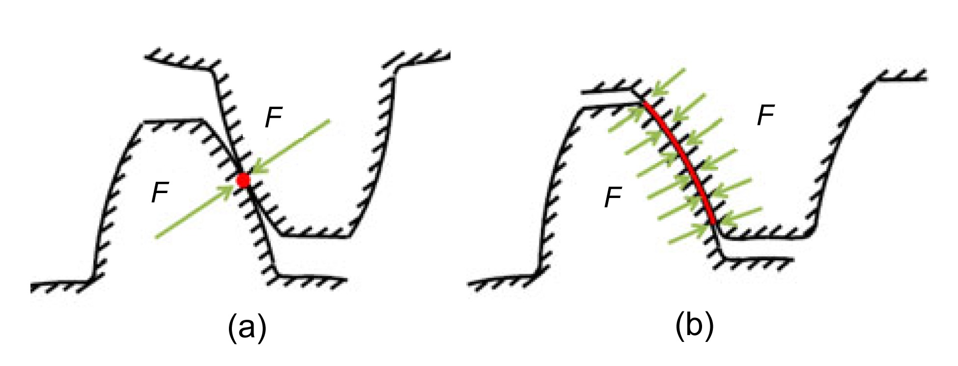
Involute spline coupling teeth are similar to gear teeth, but they work in substantially different types of conditions. In particular, in using the gears the force is transmitted, theoretically, by a point or a line, and the position of the contact point varies during the functioning of the gear due to the relative motion between the engaging teeth (Cuffaro et al., 2014); in spline couplings the force F is transmitted along the whole involute profile and there is not any relative motion between the engaging teeth, as schematically shown respectively in Figs. 1a and 1b (Curà et al., 2013).
Fig.1 Contact in gear teeth (a) and spline coupling teeth (b)
In both gears and splined coupling teeth (Cornell, 1981), the load application point is very important when calculating the individual tooth deformation or its stiffness: as a matter of fact, an error concerning the application point may cause a different value of stiffness and a variation in the engaging phenomena of the teeth.
Teeth stiffness is an important parameter in splined couplings when calculating the contact pressure distribution between the teeth (Adey et al., 2000; Tjernberg, 2001a; Medina and Olver, 2002; Barrot et al., 2009; Cuffaro et al., 2012; Curà et al., 2013). Many theoretical models calculated the teeth stiffness of the gears and splined couplings (Silvers et al., 2010), considering the individual tooth as a cantilever beam (Cornell, 1981) subjected to different loading conditions, as bending, shear, and compression; in addition, the contribution of the root deformation was also taken into account in performing these calculations (Vogt, 1925; O’Donnell, 1960). The effect of the individual tooth profile (Terauchi and Nagamura, 1981), pressure angle (Oda et al., 1986), and the load conditions (Weber, 1949) were also investigated as part of ongoing studies.
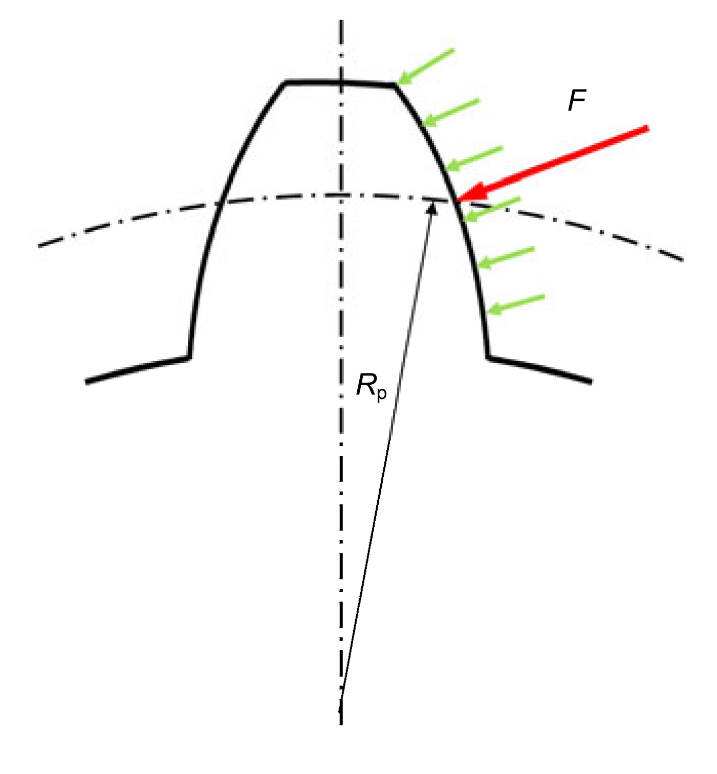
In calculating teeth stiffness of spline couplings, many previous studies considered the resultant load as applied on a point of the pitch diameter Rp (Weber, 1949; Dudley, 1957; Liu and Zhao, 2007; Silvers et al., 2010), as shown in Fig. 2. In this way, the calculation of the teeth deflection was carried on by considering the teeth as a cantilever beam loaded at its extremity. This hypothesis used an approximation in the calculations, because the load distribution along the teeth height was not uniform (Barrot et al., 2006), but many studies evaluated the exact application point of the actual force resultant and discussed the corresponding approximation in the calculations. This assumption is investigated in this work.
Fig.2 Distributed load on a spline coupling teeth and its resultant force F
Considering splined couplings, the resultant contact force may vary not only due to the pressure distribution along the teeth heights, but also because of possible misalignment conditions, which can cause parallel offsets (Weber, 1949). In these cases, when the torque was applied on the spline coupling, at the initial phase only, one tooth pair was engaged and only one edge of the tooth was in contact; then, by increasing the torque, the tooth deformation allowed all teeth surfaces to be in contact. In this particular case, the problem related to the calculation of the tooth deformation in publications was also bypassed by considering the tooth as a cantilever beam loaded into the corresponding pitch diameter (Silvers et al., 2010).
In this work, the position of the application point of the resultant contact force in the involute spline coupling teeth and the corresponding effects are investigated. This study is carried out by using finite element method (FEM) models, and considers spline couplings in ideal conditions and also with parallel offset misalignments.
2. Calculation of the resultant application point
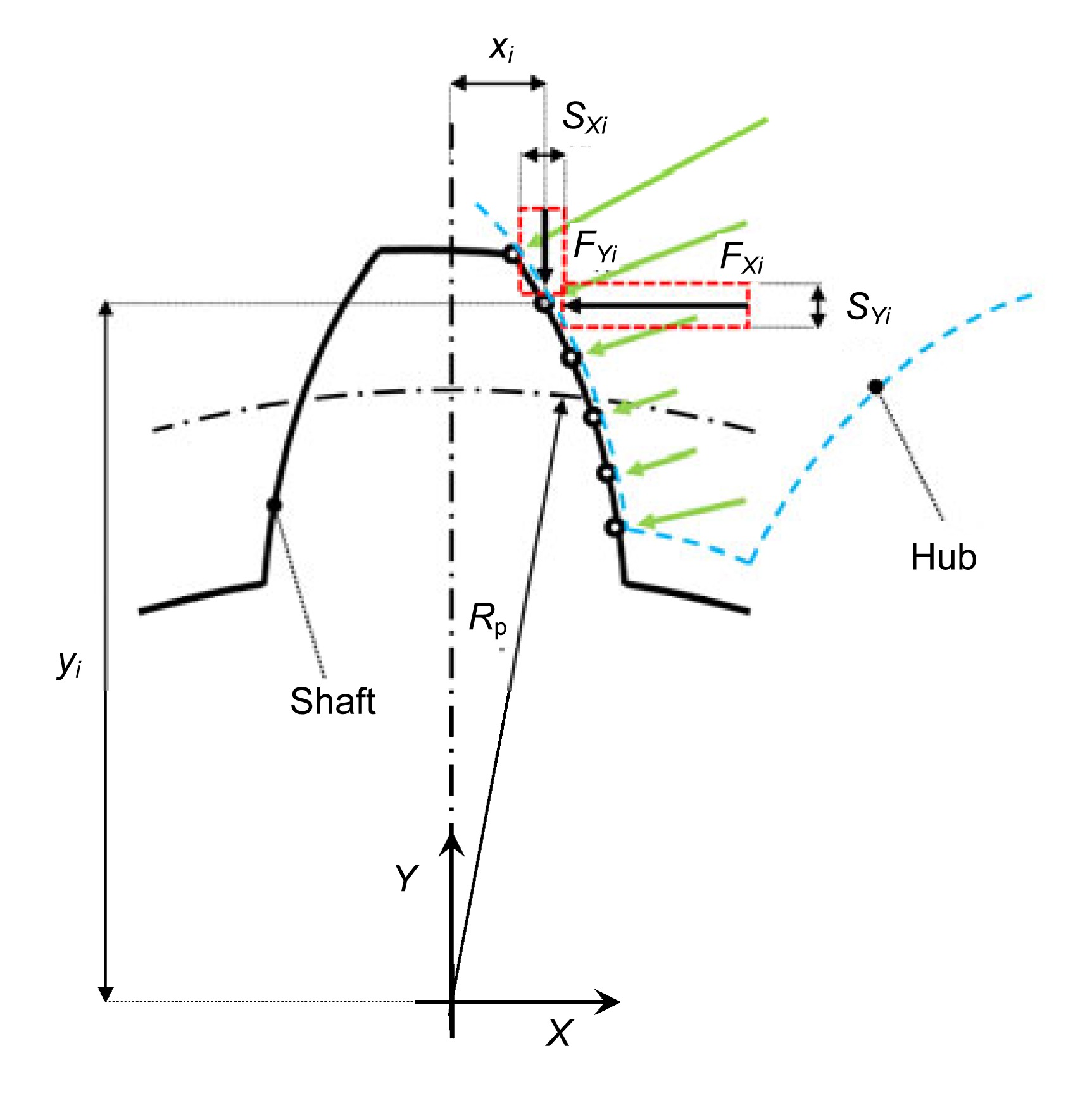
Load distribution along the tooth profile is not uniform (Barrot et al., 2006) and its trend cannot be reproduced as a simple function (i.e., linear, parabolic, etc.), so it is not easy to analytically determine the resultant application point. In this work, the load distribution has been obtained by means of FEM models giving the nodal force applied on each point of the contact profile, so the load distribution can be approximated as a series of rectangular shapes with the force magnitude as the height and the element dimension as the base (Fig. 3). Then, the application point can be obtained by calculating the center of the area for the corresponding rectangular shapes.
Fig.3 Scheme of the contact forces obtained by the FEM models
The coordinates for this center of the area (Fig. 3), corresponding to the coordinates of the resultant application point (XR, YR), can be calculated by the following classical equations (Curti and Curà, 1999):
,
,
where
,
,
,
,
where xi and yi is the X and Y coordinate of the ith nodal force, AXi and AYi is the area contribution in the X and Y direction, FXi and FYi is the component along the X and Y direction of the ith nodal contact force (all nodal forces are expressed in N), sXi and sYi are the ith element thickness projected along the X and Y direction, respectively. Note that for the first and the last nodes in contact (Fig. 3), the area values should be calculated by taking into account only one half of the element thickness: AX1=FX1·sX1/2, AY1=FY1·sY1/2, AXn=FXn·sXn/2, and AYn=FYn·sYn/2.
The resultant radius Rr, corresponding to the resultant application point, is given by
.
3. Finite element method models
Three 2D FEM models were created to study the resultant contact force in a spline coupling in ideal conditions, with respectively 0.02 mm and 0.08 mm parallel offset values.
Fig. 4 shows an example of spline coupling 2D model (obtained using 2D plain strain solid elements), whose characteristics are given in Table 1.
Fig.4 Spline coupling FEM model
Table 1
Spline coupling parameters
Parameter
Value
Modulus (mm)
1.27
Number of teeth
26
Pitch diameter (mm)
33.02
Pressure angle (°)
30
Material
Steel
Elastic modulus (MPa)
206 000
Poisson’s ratio
0.3
The nodes on the hub outer diameter were bounded in all directions, excluding the radial displacement (in this way the radial expansion, due to the radial component of the contact load between teeth, is allowed), and the load was applied on the nodes of the shaft’s inner diameter (Fig. 4).
The contact between the teeth was modelled by means of contact elements.
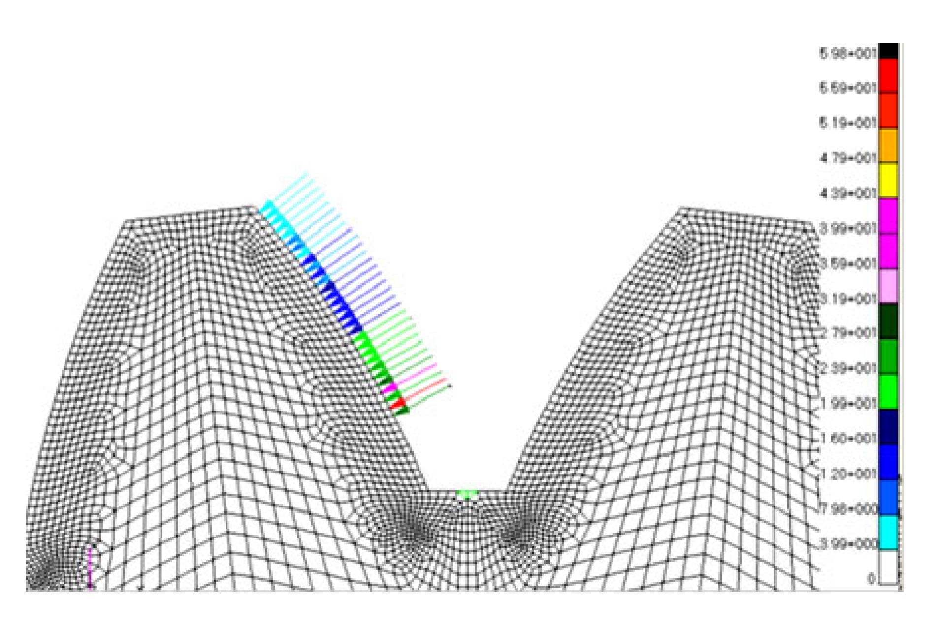
FEM results provide the load distribution along the teeth height, in terms of contact forces shared between nodes of the engaging teeth. Fig. 5 shows the mesh of the model and the obtained results in terms of load distribution (nodal forces were considered).
Fig.5 Spline coupling mesh and load distribution (The color legend represents the contact force in N)
The FEM model in nominal conditions was run with five different loading levels: 200, 500, 1000, 3000, and 5000 N·m. FEM models with parallel offset misalignments have been run with three load levels, 200, 1000, and 5000 N·m. Totally, 11 test cases were considered.
4. Results and discussion
The load application diameter, obtained by the calculations in nominal condition (no parallel offset misalignment) for each loading level, was compared with the theoretical value related to the pitch diameter.
Table 2 shows the results obtained for the five test cases, where the spline coupling was considered in nominal conditions (without parallel offset misalignment), including the applied torque, the load application diameter, and the percentage differences between calculated and nominal (pitch) diameters.
Table 2
Comparison between nominal (pitch) and calculated diameters
Test case
Torque (N·m)
Load application diameter (mm)
Difference (%)
1
200
32.78
0.74
2
500
32.74
0.85
3
1000
32.52
1.53
4
3000
32.50
1.57
5
5000
32.49
1.60
Table 2 shows that it is possible to observe the differences between load application and pitch diameter increases by increasing the loading level and the maximum percentage difference is 1.60% at the torque of 5000 N·m.
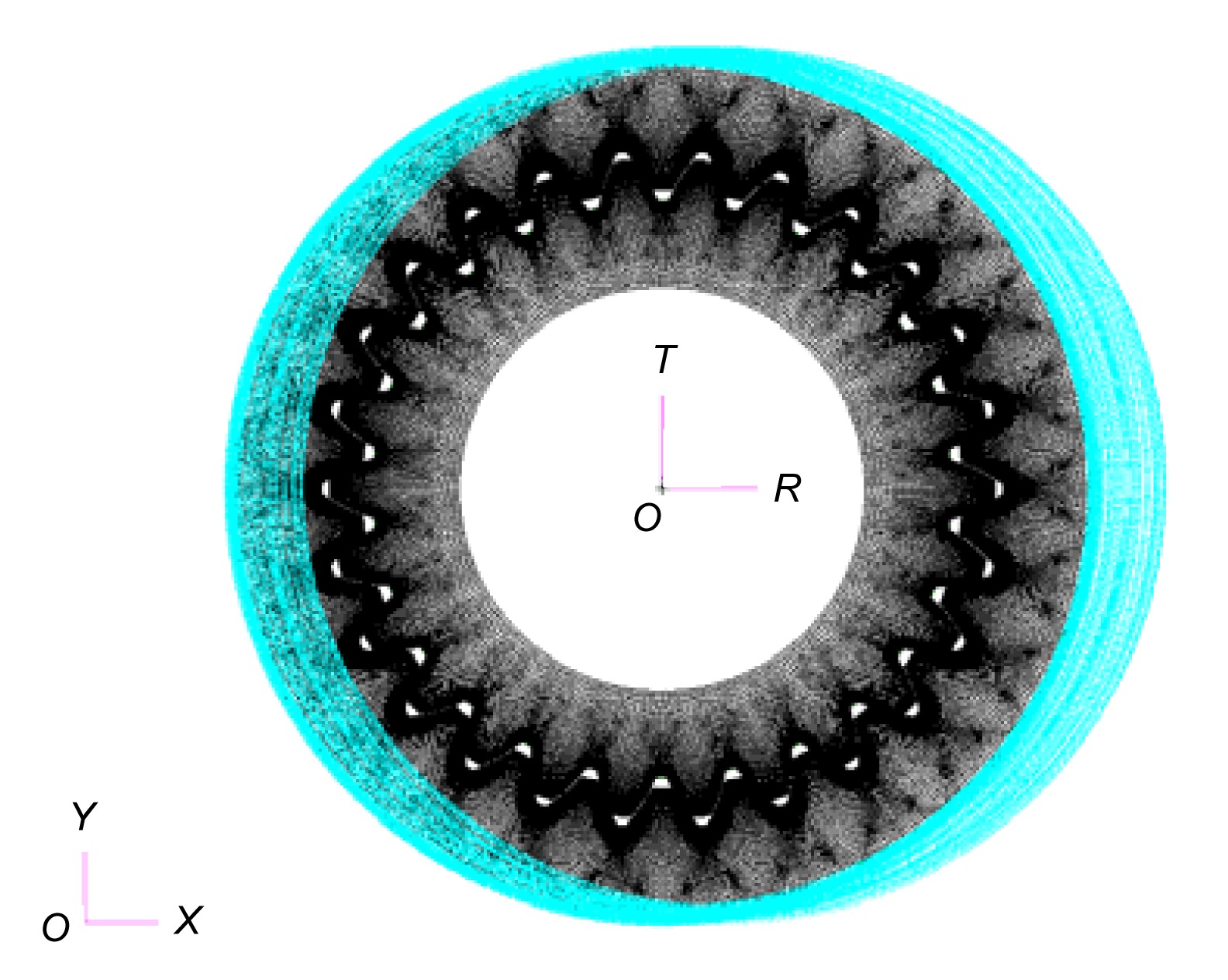
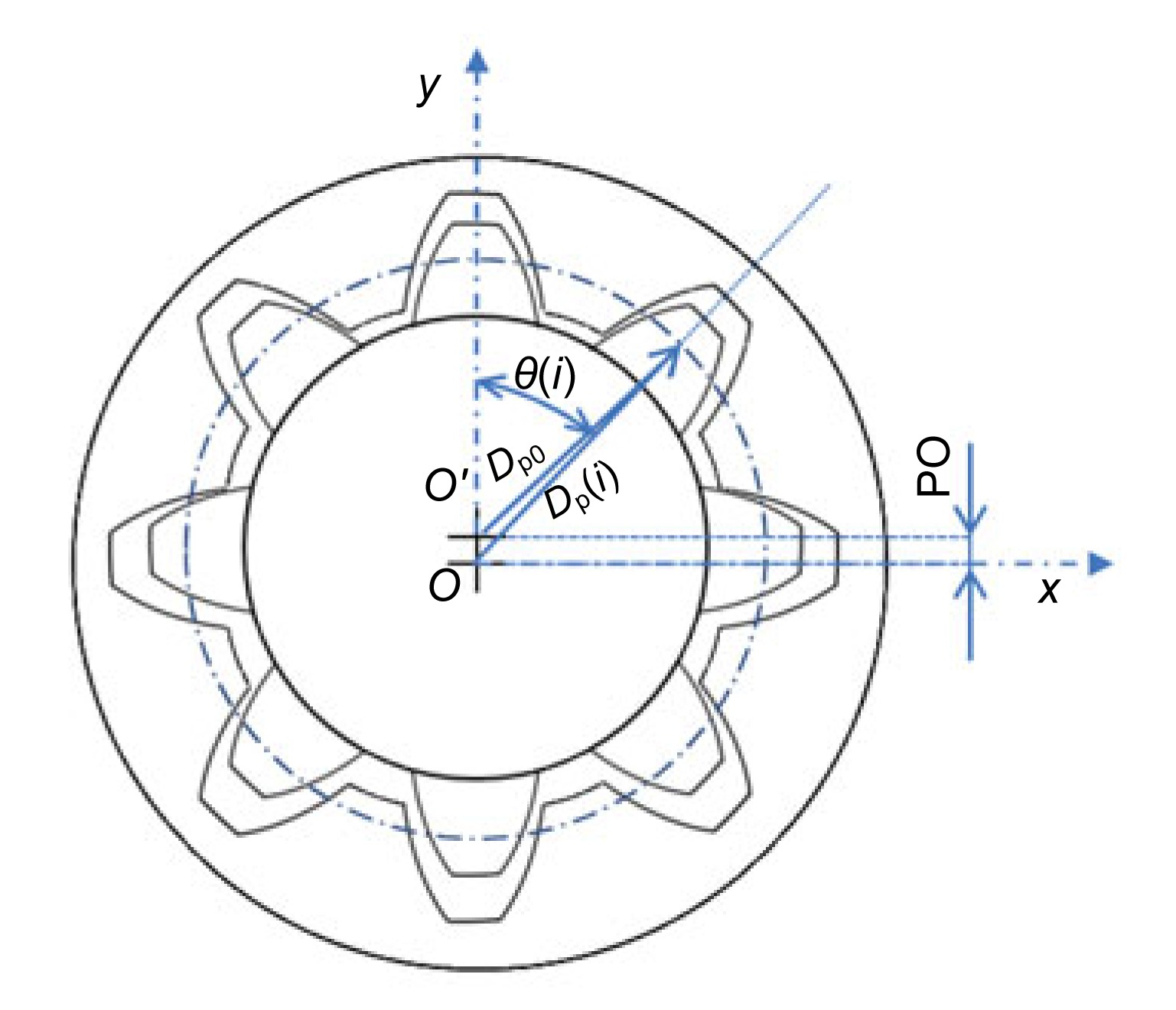
When considering spline couplings with a parallel offset error (PO) (this means that the shaft is shifted in the radial direction with respect to the hub), the theoretical pitch diameter Dp changes tooth by tooth with a sinusoidal behavior which can be calculated by
,
where Dp(i) is the ith pitch diameter corresponding to the ith tooth, PO is the parallel offset error, and θ(i) is the ith angle corresponding to the ith tooth starting from the first tooth, as shown in Fig. 6.
Fig.6 Spline coupling with parallel offset misalignment
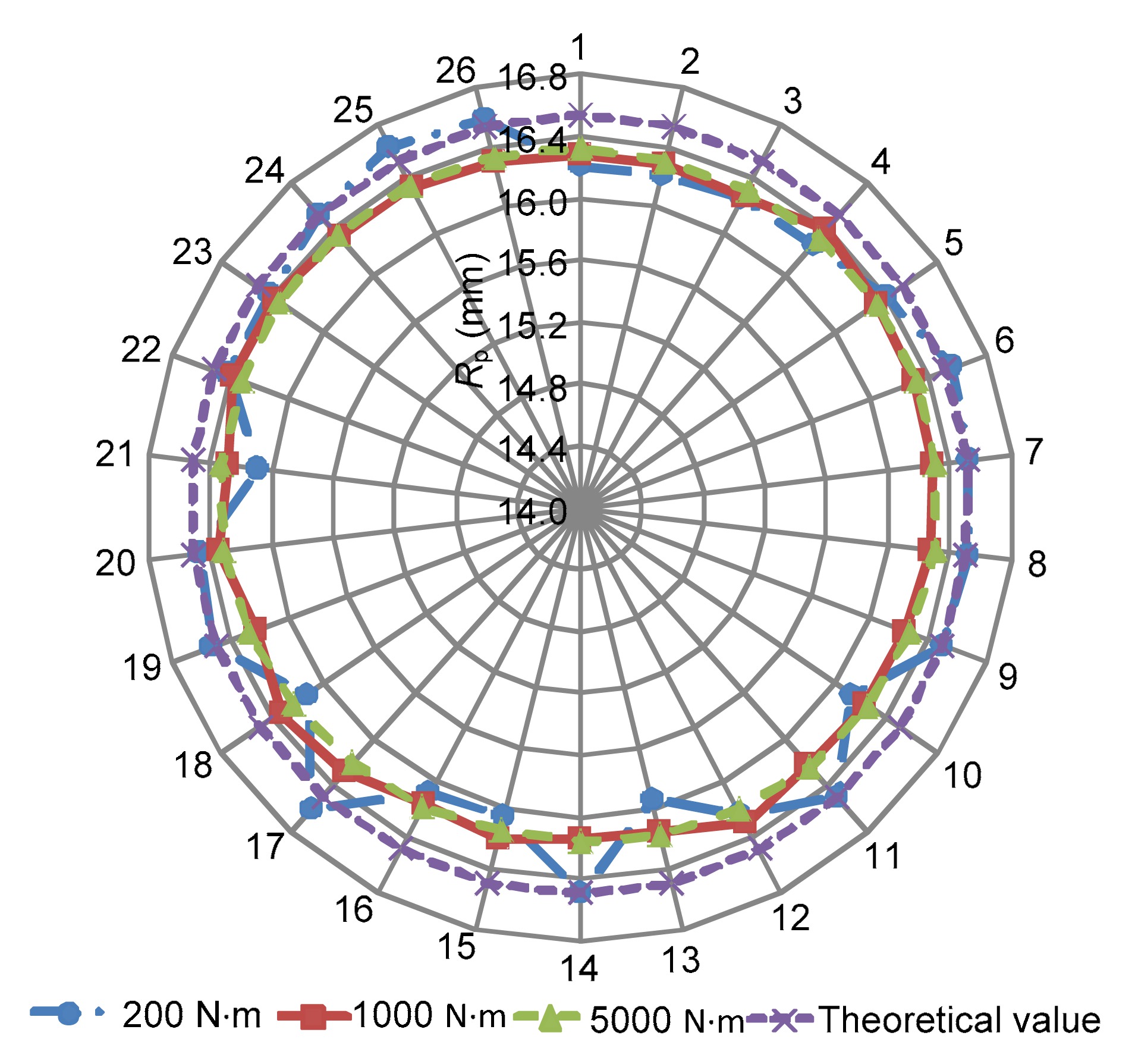
Load application diameters obtained from misaligned models were compared, tooth by tooth, with the theoretical values obtained by Eq. (6).
Results are shown respectively in Figs. 7 and 8 (0.02 mm and 0.08 mm PO misalignments), where the numbers from 1 to 26 represent the tooth number. Figs. 7 and 8 represent the load application radius obtained for each loading level (200, 1000, and 5000 N·m) for each tooth and the corresponding theoretical pitch diameters obtained by Eq. (6).
Fig.7 Pitch radius with 0.02 mm parallel offset
Fig.8 Pitch radius with 0.08 mm parallel offset
Fig. 7 shows that for the case of the 0.02 mm misalignment, the load application diameter decreases by the increase of the loading level. In this case, the maximum percent difference between FEM results and the theoretical pitch diameter is 1.60%, obtained with a torque of 5000 N·m.
Considering the spline coupling with 0.08 mm parallel offset misalignment, results for the 200 N·m torque are less uniform with respect to the other case; this fact may be due to the high misalignment level that, with a relative low load value, causes an imperfect (not total) contact between teeth. However, in this case, the maximum percentage difference between FEM results and theoretical pitch diameter is 2.94%, obtained with a torque of 200 N·m.
The results presented above show a small difference between the theoretical application point of the resultant force and the actual one. However, by calculating the tooth stiffness with the actual load application point, it is possible to emphasize that this approximation produces a fundamental effect on the tooth stiffness.
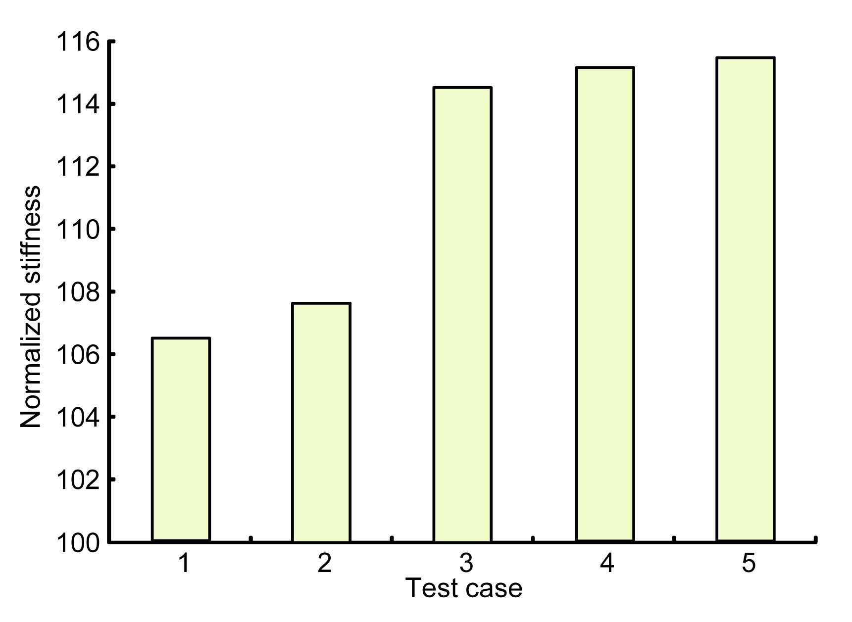
In particular, Fig. 9 shows the comparison between the normalized tooth stiffness (normalized respect to the stiffness nominal value obtained with the theoretical load application point at the pitch diameter) calculated with the model described in (Curà and Mura, 2013) by using the load application points presented in Table 2. Tooth stiffness was obtained, as already described, by considering the tooth as a cantilever beam whose deformation was obtained as the sum of three elastic contributions: bending, shear, and tooth root deformation (Curà and Mura, 2013).
Fig.9 Comparison between normalized tooth stiffness values (test cases of Table 2)
It is possible to observe that a small difference in the approximation of the load application point (up to 1.60%) brings about a more important difference related to the tooth stiffness value (up to about 15%) (Fig. 9).
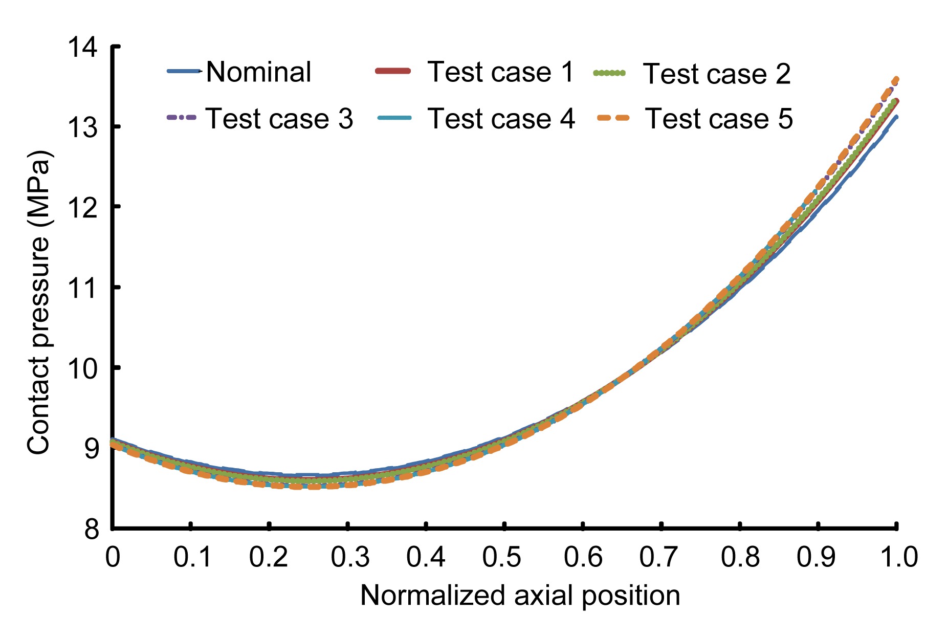
Fig. 10 shows the effect of the teeth stiffness on the axial pressure distribution. This figure represents the contact pressure trend versus the normalized axial position, obtained by dividing the actual axial position by the tooth width (Cuffaro et al., 2012). Pressure distributions was obtained by means of the Tjernberg model (Tjernberg, 2001b), with a 200 N·m torque and considering different tooth stiffness values, obtained for different resultant force application points described as follows: (1) nominal case, stiffness corresponding to the pitch diameter; (2) test cases 1 to 5, stiffness corresponding to those reported in Table 2.
Fig.10 Comparison between axial contact pressure trends
5. Conclusions
In this work, the position of the resultant force shared in the involute spline coupling teeth due to the contact pressure distribution was investigated. This study verified the approximation which considers the resultant contact force in spline coupling engaging teeth applied on the pitch diameter.
The investigation was conducted using FEM models. The resultant force application diameter was numerically obtained for a spline coupling in nominal conditions and with parallel offset misalignments. In particular, two levels of parallel offset misalignment were considered (0.02 mm and 0.08 mm). For each case, different loading levels were applied.
Results show that in nominal conditions, the difference between load application diameter and pitch diameter increases with the increase of loading level and the maximum difference is 1.60%. In models with parallel offset misalignment, the maximum difference between FEM results and theoretical pitch diameter is 2.94%, obtained in the case of a 0.08 mm misalignment.
In general, it is possible to point out that the differences between the load application diameter and pitch diameter is not very high in both ideal coupling and with the parallel offset misalignment spline coupling, but this approximation becomes more important if the tooth stiffness is calculated with the actual load application points. In fact, the difference between the stiffness values obtained considering the load applied on the pitch diameter and those obtained with the actual load application point increases to about 15%.
The effect of the load application point variations was evaluated related to the axial pressure distribution, showing that this parameter may also be influenced by the position of the load application point.
Acknowledgements
Thanks to Exemplar s.r.l., Torino, Italy for their aid in the creation of the FEM models.
References
[1] Adey, R.A., Baynham, J., Taylor, J.W., 2000. Development of analysis tool for spline couplings. Proceedings of the Institution of Mechanical Engineers, Part G: Journal of Aerospace Engineering, 214(6):347-357.
[2] Barrot, A., Paredes, M., Sartor, M., 2006. Determining both radial pressure distribution and torsional stiffness of involute spline couplings. Proceedings of the Institution of Mechanical Engineers, Part C: Journal of Mechanical Engineering Science, 220(12):1727-1738.
[3] Barrot, A., Paredes, M., Sartor, M., 2009. Extended equations of load distribution in the axial direction in a spline coupling. Engineering Failure Analysis, 16(1):200-211.
[4] Cornell, R.W., 1981. Compliance and stress sensitivity of spur gear teeth. ASME Journal of Mechanical Design, 103(2):447-459.
[5] Cuffaro, V., Cur, F., Mura, A., 2012. Analysis of the pressure distribution in spline couplings. Proceedings of the Institution of Mechanical Engineers, Part C: Journal of Mechanical Engineering Science, 226(12):2852-2859.
[6] Cuffaro, V., Cur, F., Mura, A., 2014. Experimental investigation about surface damage in straight and crowned misaligned splined couplings. Key Engineering Materials, 577-578:353-356.
[7] Cur, F., Mura, A., 2013. Experimental procedure for the evaluation of tooth stiffness in spline coupling including angular misalignment. Mechanical Systems and Signal Processing, 40(2):545-555.
[8] Cur, F., Mura, A., Gravina, M., 2013. Load distribution in spline coupling teeth with parallel offset misalignment. Proceedings of the Institution of Mechanical Engineers, Part C: Journal of Mechanical Engineering Science, 227(10):2195-2205.
[9] Curti, G., Cur, F., 1999. Comportamento Meccanico dei Materiali: Lezioni-Esercizi. (in Italian), CLUT,Torino :
[10] Dudley, D.W., 1957. How to design involute splines. Product Engineering, October,:75-80.
[11] Liu, Z.S., Zhao, G., 2007. Modeling research on radial force in gear coupling with parallel misalignment. , 12th IFToMM World Congress, Besanon, France, :
[12] Medina, S., Olver, A.V., 2002. An analysis of misaligned spline couplings. Proceedings of the Institution of Mechanical Engineers, Part J: Journal of Engineering Tribology, 216(5):269-279.
[13] Oda, S., Koide, T., Ikeda, T., Umezawa, ., 1986. Effects of pressure angle on tooth deflection and root stress. Bulletin of JSME, 29(255):3141-3148.
[14] ODonnell, W.J., 1960. The additional deflection of a cantilever due to the elasticity of the support. ASME Journal of Applied Mechanics, 27(3):461-464.
[15] Silvers, J., Sorensen, C.D., Chase, K.W., 2010. A new statistical model for predicting tooth engagement and load sharing in involute splines. AGMA Technical Resources,Alexandria, Virginia :
[16] Terauchi, Y., Nagamura, K., 1981. Study on deflection of spur gear teeth: 2nd report, calculation of tooth deflection for spur gears with various tooth profiles. Bulletin of JSME, 24(188):447-452.
[17] Tjernberg, A., 2001. Load distribution and pitch errors in a spline coupling. Materials and Design, 22(4):259-266.
[18] Tjernberg, A., 2001. Load distribution in the axial direction in a spline coupling. Engineering Failure Analysis, 8(6):557-570.
[19] Vogt, F., 1925. Uber Die Berechnung der Fundament Deformation, Avhandlinger utgil av Det Norske Videnshaps, Akademi I Oslo. , Klasse, 2, (in German), I Math-Naturv,:
[20] Weber, C., 1949. The deformation of loaded gears and the effect on their load carrying capacity, Report No. 3, Sponsored Research (Germany), British Department of Scientific and Industrial Research,:
Open peer comments: Debate/Discuss/Question/Opinion


Open peer comments: Debate/Discuss/Question/Opinion
<1>