Shuo-qiao Zhong, Jia-yang Xiong, Xin-biao Xiao, Ze-feng Wen, Xue-song Jin. Effect of the first two wheelset bending modes on wheel-rail contact behavior[J]. Journal of Zhejiang University Science A, 2014, 15(12): 984-1001.
@article{title="Effect of the first two wheelset bending modes on wheel-rail contact behavior", author="Shuo-qiao Zhong, Jia-yang Xiong, Xin-biao Xiao, Ze-feng Wen, Xue-song Jin", journal="Journal of Zhejiang University Science A", volume="15", number="12", pages="984-1001", year="2014", publisher="Zhejiang University Press & Springer", doi="10.1631/jzus.A1400199" }
%0 Journal Article %T Effect of the first two wheelset bending modes on wheel-rail contact behavior %A Shuo-qiao Zhong %A Jia-yang Xiong %A Xin-biao Xiao %A Ze-feng Wen %A Xue-song Jin %J Journal of Zhejiang University SCIENCE A %V 15 %N 12 %P 984-1001 %@ 1673-565X %D 2014 %I Zhejiang University Press & Springer %DOI 10.1631/jzus.A1400199
TY - JOUR T1 - Effect of the first two wheelset bending modes on wheel-rail contact behavior A1 - Shuo-qiao Zhong A1 - Jia-yang Xiong A1 - Xin-biao Xiao A1 - Ze-feng Wen A1 - Xue-song Jin J0 - Journal of Zhejiang University Science A VL - 15 IS - 12 SP - 984 EP - 1001 %@ 1673-565X Y1 - 2014 PB - Zhejiang University Press & Springer ER - DOI - 10.1631/jzus.A1400199
Abstract: The objective of this paper is to develop a new wheel-rail contact model, which is suitable for considering the effect of wheelset bending deformation on wheel-rail contact behavior at high speeds. Dummies of the two half rigid wheelset are introduced to describe the spacial positions of the wheels of the deformed wheelset. In modeling the flexible wheelset, the first two wheelset bending modes are considered. Based on the modal synthesis method, these mode values of the wheelset axle are used to solve the motion equations of the flexible wheelset axle modeled as an Euler-Bernoulli beam. The wheel is assumed to be rigid and always perpendicular to the deformed axle at the wheel centre. In the vehicle model, two bogies and one car body are modeled as lumped masses. Spring-damper elements are adopted to model the primary and secondary suspension systems. The ballasted track is modeled as a triple layer discrete elastic supported model. Two high-speed vehicle-track models, one considering rigid wheelset models and the other considering flexible wheelset models, are used to analyze the differences of the numerical results of the two models in both frequency and time domains. In the simulation, a random high-speed railway track irregularity is used as wheel-rail excitations. Wheel-rail forces are calculated and analyzed in the time and frequency domains. The results clarify that this new contact model can characterize very well the influence of the first two bending modes of the wheelset on contact behavior.
Darkslateblue:Affiliate; Royal Blue:Author; Turquoise:Article
Article Content
1. Introduction
High-speed railways are currently popular globally. However, there are some problems including passenger riding comfort, noise pollution, and even operational safety (Jin et al., 2013). Rail corrugation, rail welding irregularity, wheel burning, and wheel out-of-roundness (OOR) generate high-frequency components of the dynamic wheel-rail contact forces that contribute significantly to the total wheel-rail contact forces (Nielsen et al., 2003), and reduce the life of the components of track and vehicle, such as wheels, rails, and fasteners. Rail grinding and wheel re-profiling are the most common measures that have been proved to be effective in controlling rail irregularities and wheel OOR. However, these measures lead to notably high maintenance costs. A lot of measurements at the sites and coupling vehicle-track dynamics modeling have been carried out to investigate the mechanism and development of these phenomena. In the vehicle-track dynamics modeling, a rigid multi-body system is often adopted to simulate railway vehicles, based on several commercial codes available for the low-frequency domain, such as GENSYS, NUCARS, SIMPACK, and VAMPIRE. These computer programs are generally used to analyze railway vehicle dynamics responses at frequencies below 20 Hz, where the influence of rigid motions of the vehicle on wheel-rail contact forces is dominant (Nielsen et al., 2005). To analyze the vehicle dynamic responses at mid- and high-frequencies, the vehicle structural flexibility should be taken into account in the modeling. It is obvious that wheelset structural flexibility has an influence on wheel-rail contact behaviors at mid- and high-frequencies. Different flexible wheelset models have been set up due to various motivations in the past (Chaar, 2007).
The methods applied to modeling flexible wheelset can be summarized as three major categories (Chaar, 2007). The first is a lumped model developed in a simple and convenient way, in which a wheelset is divided into several parts interconnected with springs and dampers. This model can describe the bending and torsional motions of the wheelset with only a few degrees of freedom, which could not be applied to studying wear phenomena on wheel treads or rails (Popp et al., 1999). The second is a continuous model developed by Szolc (1998a; 1998b), in which the wheelset axle was modeled as a beam, and two wheels and brake discs were modeled as rigid rings attached to the axle through a massless, elastically isotropic membrane. The model can characterize the wheelset dynamic behavior in the frequency range of 30–300 Hz. In the model proposed by Popp et al. (2003), the wheelset axle was considered as a 1D continuum, having the properties of a bar, a torsional rod, and a Rayleigh beam. The wheel was considered as a 2D continuum, having the properties of a disc and a Kirchhoff plate. The third was developed based on finite element method (FEM), which simulates wheelset flexibility more realistically than the first two categories of model. The wheelset modes and corresponding natural frequencies were obtained through the modal analysis of the finite element (FE) model by using the commercial software, and they were input into the simulation by means of the commercial codes (SIMPACK, NEWEUL) (Meinders and Meinker, 2003) or some non-commercial multi-body dynamic system codes. The non-commercial code developed by Fayos et al. (2007) and Baeza et al. (2008; 2011) introduced the Eulerian coordinate system to replace the Lagrangian coordinate system in the flexible wheelset modeling. In this way it is convenient to obtain the motion of fixed physical nodes, and consider the inertial effect due to wheelset rotation. Relying on current computing power, it is feasible to use FEM to consider the effect of flexible wheelset in modeling a railway vehicle coupling with a track.
Regarding the wheel-rail contact treatment in considering flexible wheelset influence, wheel-rail rolling contact condition is simplified based on different prior assumptions, especially in the detection of wheel-rail contact points. This is the prerequisite for the calculation of wheel-rail creepages and contact forces. Baeza et al. (2011) neglected the effect of the high-frequency deformation and the deviation of a rotating flexible wheelset rolling over a flexible track model on the wheel-rail contact point in the investigation into the effect of the rotating flexible wheelset on rail corrugation. Through the detailed calculation Kaiser and Popp (2006) found that the contact point was in the location where the wheel and the rail had positive penetration maxima, and the penetration direction was orthogonal to the common tangent plane of the wheel and the rail before their deformations. A linear wheel-rail contact model was proposed and used to carry out the detection of wheel-rail contact point and the contact zone’s normal direction (Andersson and Abrahamsson, 2002). In the detection, the functions were created using a first-order Taylor expansion around a reference state described by a group of parameters which represent a configuration, in which the train was in static equilibrium and the wheel and the track were free from geometric imperfections. The advantage of this approach is that the contact position and orientation in each time step can be calculated by interpolation replacing iterations, which results in a low computational cost. But the approach is only suitable for the case that the effect of all the parameters is very small on the contact point position and the contact patch orientation around the references is in static equilibrium. The wheel-rail contact point position and the contact patch orientation greatly depend on parameters, such as the curvatures of wheel and rail. In (Torstensson et al., 2012; Torstensson and Nielsen, 2011), the contact point detection was done before the simulation and used in the subsequent time integration analysis in the form of look-up table. The commercial software GENSYS allows for such calculations using the pre-processor KPF (from Swedish contact point function). In the KPF, the location and orientation of the contact patch were assumed to be dependent only on the relative displacement in the lateral direction between the wheelset and the rails, and hence the influence of the wheelset yaw angle was not taken into account. In some other papers detailed discussions on the wheel-rail contact model were omitted. In this study, the wheel-rail contact model considering the effect of wheelset flexibility (Zhong et al., 2013; 2014) is further improved and the new contact model is suitable for the analysis on the effect of the local higher-frequency deformation of the wheels on the wheel-rail contact behavior.
2. Vehicle-track coupling dynamic system
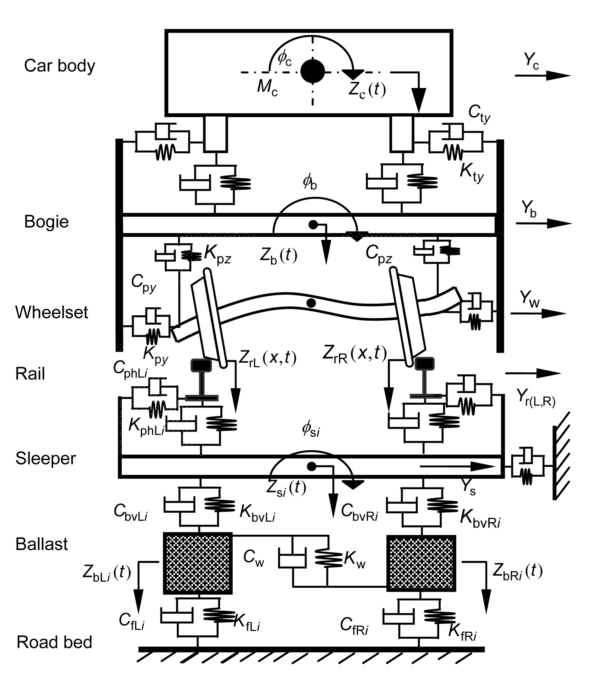
A flexible wheelset model (to be illustrated in Section 2.1) and a suitable wheel-rail contact model (to be discussed in Section 2.2) are integrated into the vehicle-track coupling dynamic system model. All parts of the vehicle system, except for its four wheelsets, are considered as rigid bodies. The primary and secondary suspension systems of the vehicle are modeled with spring-damper elements. A triple layer model of discrete elastic support is adopted to simulate the ballasted track. The rails are modeled as Timoshenko beams. The sleepers are modeled as rigid bodies and the ballast model consists of discrete equivalent masses. The equivalent spring-damper elements are used as the connections between the rails and the sleepers, the sleepers and the equivalent ballast bodies, and the ballast bodies and the roadbed. Fig. 1 shows the vehicle-track coupling dynamic system model. The equations of motion of each component of the vehicle excluding wheelsets and the track are illustrated in detail in (Xiao et al., 2007; 2008; 2010). The parameters and their values describing the dynamic models are given in Appendix A.
Fig.1 Vehicle-track coupling model (elevation)
2.1. Flexible wheelset model
The wheelset structural flexibility is considered by modeling the wheelset axle as an Euler-Bernoulli beam in two planes, one perpendicular to the track centerline and the other parallel to the track level. The crossing effect of the bending deformations in the two planes is ignored. In the first two bending modes obtained using the modal analysis of the FE model of a wheelset, two wheels have little deformation (Fig. 2), and their frequencies are in the available frequency range (0–500 Hz) of an Euler-Bernoulli beam model. Therefore, two wheels can be treated as rigid bodies in this study.
Fig.2 The first two bending modes obtained using FE model
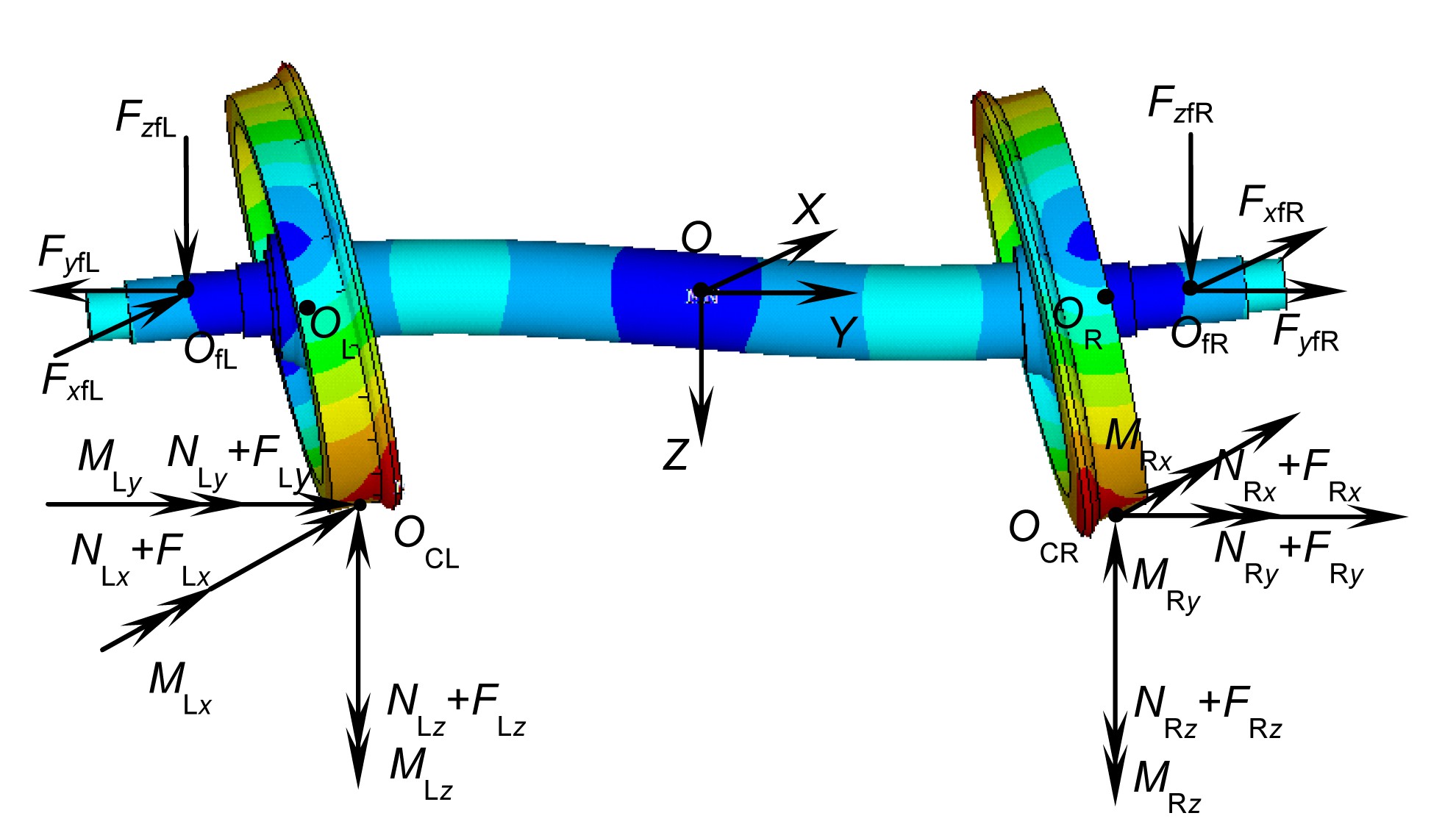
There are two force systems acting on the wheelset, one is the wheel-rail contact forces and the other is the forces of the primary suspension system (Fig. 3).
Fig.3 Force analysis diagram of the flexible wheelset
In Fig. 3, OfL and OfR are the left and right points on the axle, respectively, where the primary suspension force systems are applied. OCL and OCR are the left and right contact points of wheel-rail, respectively. O indicates the origin of the coordinate system O-XYZ that is a coordinate system with a translational motion along the tangent track centerline at operational speed. If the speed is constant, this coordinate system is an inertial coordinate system, and therefore regarded as an absolute coordinate system (geodetic coordinate system).
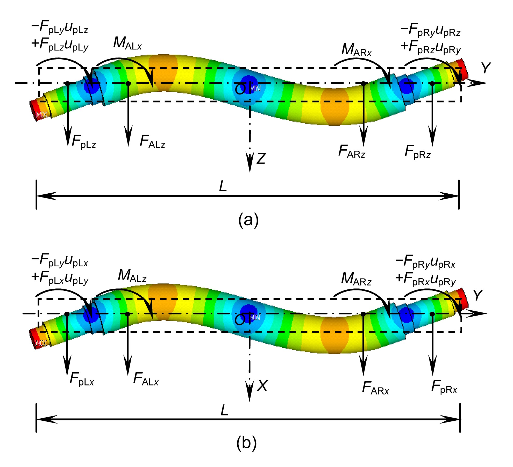
To analyze the axle’s deformation, the force systems from wheel-rail interaction acting on the left and right wheel treads are translated to the nominal circle centers OL and OR, respectively, and extra moments are produced in the procedure of translating contact forces. Thus, the force systems acting on the axle in the two planes are obtained in Fig. 4.
Fig.4 Force analysis diagram in the plane O-YZ (a) and in the O-XY plane (b)
The notations of the variables and symbols are defined in Table 1. The subscript p denotes the primary suspension, the subscripts x, y, and z denote X-, Y-, and Z-direction, respectively, and A denotes the axle.
Table 1
The notations of the variables
Variable
Explanation
upLz, upRz
Z-direction components of the displacements of the nodes where the left and right primary suspension forces are applied on the axle, respectively
upLy, upRy
Y-direction components of the displacements of the nodes where the left and right primary suspension forces are applied on the axle, respectively
upLx, upRx
X-direction components of the displacements of the nodes where the left and right primary suspension forces are applied on the axle, respectively
L
Length of the wheelset axle
FpLx, FpLy, FpLz
X-, Y-, and Z-direction components of the primary suspension forces on the left sides of a wheelset
FpRx, FpRy, FpRz
X-, Y-, and Z-direction components of the primary suspension forces on the right sides of a wheelset
FALx, FALy, FALz
X-, Y-, and Z-direction components of the forces between the left wheel and the axle of a wheelset
FARx, FARy, FARz
X-, Y-, and Z-direction components of the forces between the right wheel and the axle of a wheelset
MALx, MALz
X- and Z-direction components of the moments between the left wheel and the axle of a wheelset
MARx, MARz
X- and Z-direction components of the moments between the right wheel and the axle of a wheelset
E
Young’s modulus
Ix
Cross-sectional area moment of inertia about the X axis
Iz
Cross-sectional area moment of inertia about the Z axis
t
Time
uz(y,t), ux(y,t)
X- and Z-direction components of the displacements of the nodes on the axle at time t, respectively
Qz(y,t), Qx(y,t)
X- and Z-direction components of the forces on the axle at time t, respectively
Mz(y,t), Mx(y,t)
X- and Z-direction components of the moments on the axle at time t, respectively
mw
Mass of a wheel
g
Gravity acceleration
aLz, aRz
Z-direction components of the accelerations of the left and right wheels, respectively
aLx, aRx
X-direction components of the accelerations of the left and right wheels, respectively
Jw
Mass moment of inertia about the diameter of the wheel
αLx, αRx
X-direction components of the angular acceleration of the left and right wheels, respectively
αLz, αRz
Z-direction components of the angular acceleration of the left and right wheels, respectively
u′z(y,t), u′x(y,t)
The first derivative of uz(y, t), ux(y, t) with respect to y, respectively
ywL, ywR
y coordinates of the joints of the left and right wheels and the axle, respectively
FwrLx, FwrLy, FwrLz
X-, Y-, and Z-direction components of the left wheel-rail contact forces, respectively
FwrRx, FwrRy, FwrRz
X-, Y-, and Z-direction components of the right wheel-rail contact forces, respectively
OcL, OcR
Left and right wheel-rail contact point, respectively
OwL, OwR
Centers of the nominal circles of the left and right wheels, respectively
OwL-XwLYwLZwL, OwR-XwRYwRZwR
Body coordinate systems attached to the left and right wheels, respectively
qzk,
The kth generalized coordinate and the kth generalized acceleration coordinate in the plane O-YZ
qxk,
The kth generalized coordinate and the kth generalized acceleration coordinate in the plane O-XY
ωk
The kth circular frequency
N
Considered number of the modes
Uzk(y), U′zk(y)
The kth mode function of the axle in the O-YZ plane and its first derivative with respect to y
Uxk(y), U′xk(y)
The kth mode function of the axle in the O-XY plane and its first derivative with respect to y
The differential equation for the flexural vibration of an Euler-Bernoulli beam (the axle) in the plane O-YZ is written as
,
where
,
.
The force analysis diagram of the two wheels including the D’Alembert forces is shown in Fig. 5, based on which differential equations of motion of the two wheels are written as
,
.
Fig.5 Force analysis diagram of the two wheels
Note that the lateral accelerations of the wheels are assumed to be the same as the wheelset axle so there is no relative motion between wheels and axle.
Substituting the expressions of FA(L,R)z and MA(L,R)x obtained through Eqs. (4) and (5) into Eqs. (2) and (3), respectively, we can obtain:
,
,
,
where
.
Consider a solution of Eq. (8) in the form:
.
Using the calculus of variation (Qiu et al., 2009), the modal function satisfies:
,
,
,
where δij is the Kronecker delta. For i=j, Eq. (11) can be written as
.
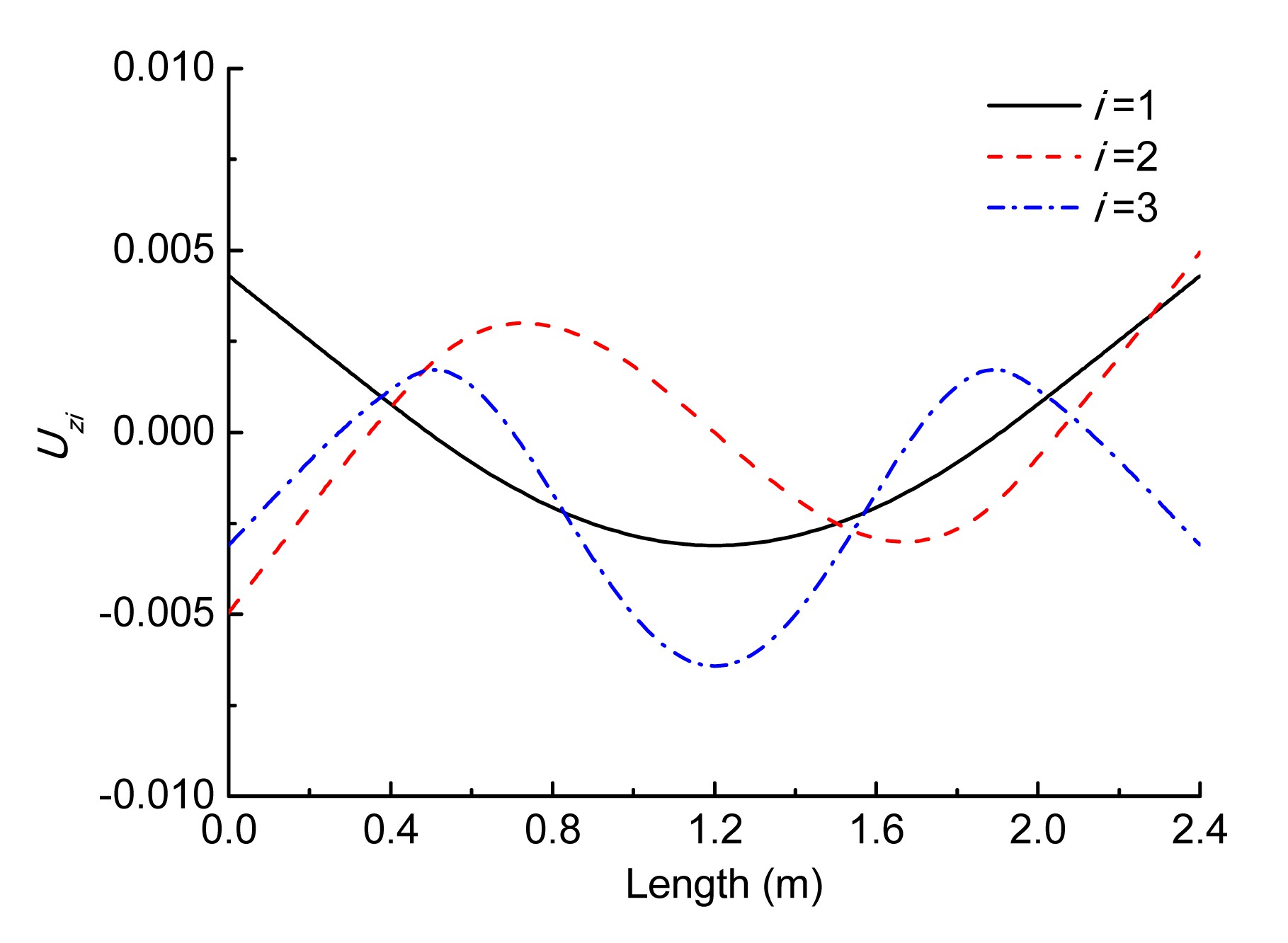
To obtain the mode shape functions with the wheelset axle modeled as a uniform Euler-Bernoulli beam carrying two particles (wheels), the segment of the beam from the left end to the first particle is referred to as the first portion, in between the two particles as the second portion and from the second particle to the right end as the third portion. The beam mode shape will be the superposition of the mode shapes of the three portions. The derivation of the mode shape functions is presented in Appendix B. The first three modes have the frequencies of f1=111 Hz, f2=245 Hz, and f3=547 Hz, respectively. These mode shape functions are normalized so as to satisfy Eq. (14), as shown in Fig. 6. The third mode is not in the frequency range of 0–500 Hz where the Euler-Bernoulli beam is available to analyze the system. Hence, the effect of the first two modes on dynamic responses is conducted in this study.
Fig.6 The first three bending mode shapes of the wheelset
According to the modal analysis, we let the solution of Eq. (8) have the form:
.
Substituting Eq. (15) into Eq. (8), the differential equation can be written as
.
Multiplying both sides of Eq. (16) by and integrating over the domain 0<y<L, we can obtain:
.
Using the orthogonality of the modal shape function as expressed in Eqs. (11) and (13), Eq. (17) can be written as
,
where
.
Eq. (18) can be expressed as
.
Eq. (20) can be written in the matrix form:
,
where
The explicit integral method illustrated in (Zhai, 2007) is used to obtain the vector of each acceleration coordinate.
For the vibration in the plane YOX, the differential equation expressed with respect to can be written as
.
The derivation of Eq. (23) is similar to that of Eq. (20) and omitted here. Eq. (23) can be expressed in matrix form:
,
where
2.2. Wheel-rail contact model
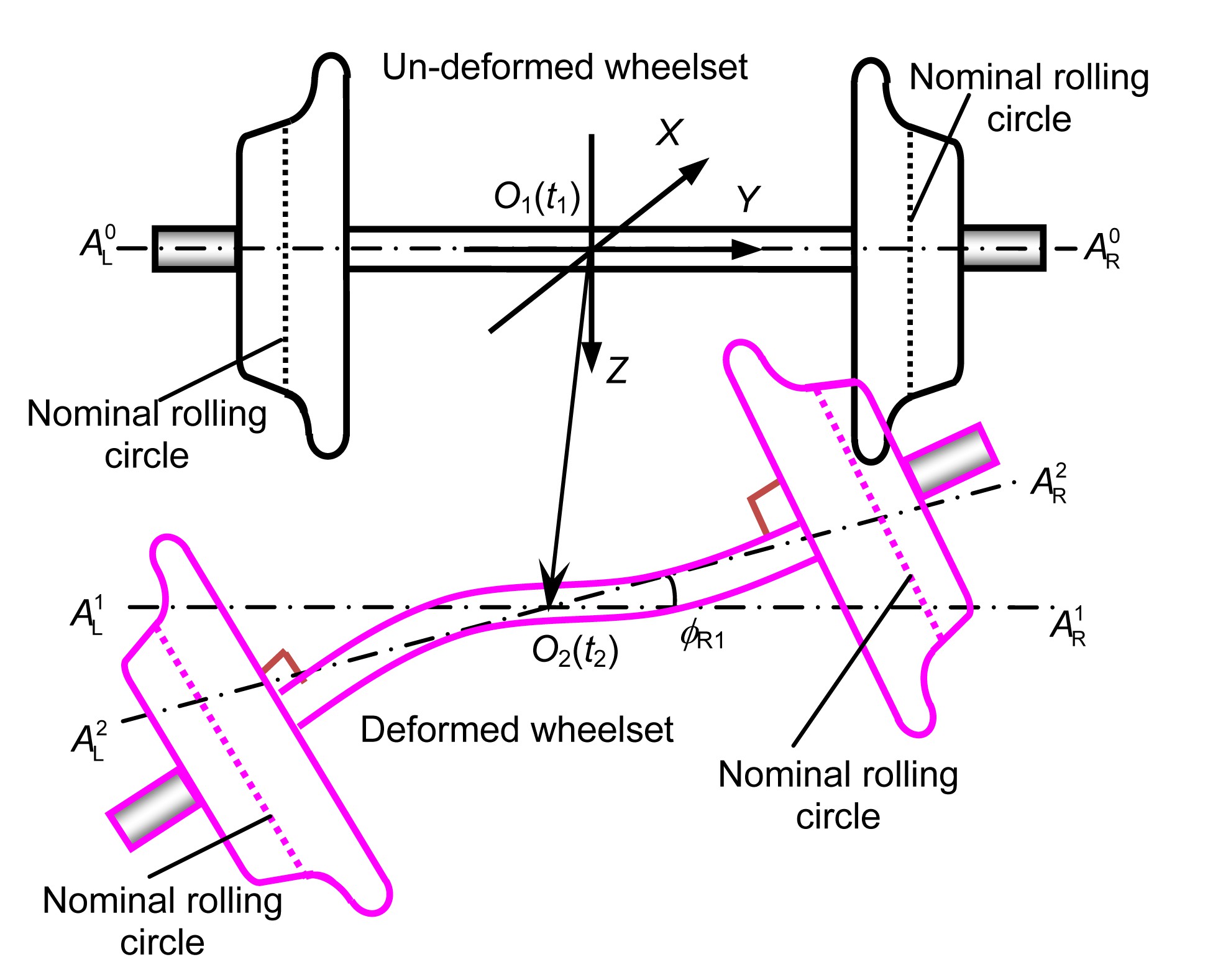
As mentioned in Section 2.1, the main concern in this work is the wheelset axle bending. The wheels are assumed to be rigid and their nominal rolling circles are always perpendicular to the deformed wheelset axle at their interference fit surfaces. Fig. 7 shows that the flexible wheelset moves from its initial reference state (O1(t1)) to its t2 status (O2(t2)), which is described in the plane of O-YZ. O1 is the center of the un-deformed wheelset at t1, and O2 is the center of the deformed wheelset at any time t. O1O2 is the displacement vector of the wheelset center due to its rigid motion, and ϕR1 is the roll angle due to the wheelset rigid motion. The auxiliary line, ,
is the central line of the un-deformed wheelset axle, is obtained by moving from O1(t1) to O2(t2), and is obtained through rotating by ϕR1. is actually the central line of the rigid wheelset axle at t2. Fig. 7 shows that the wheels are assumed to be rigid and always perpendicular to the deformed axle line at their connections at any time t2.
Fig.7 A flexible wheelset moving from its initial reference state (O1(t1)) to its any status (O2(t)) in the plane of O-YZ
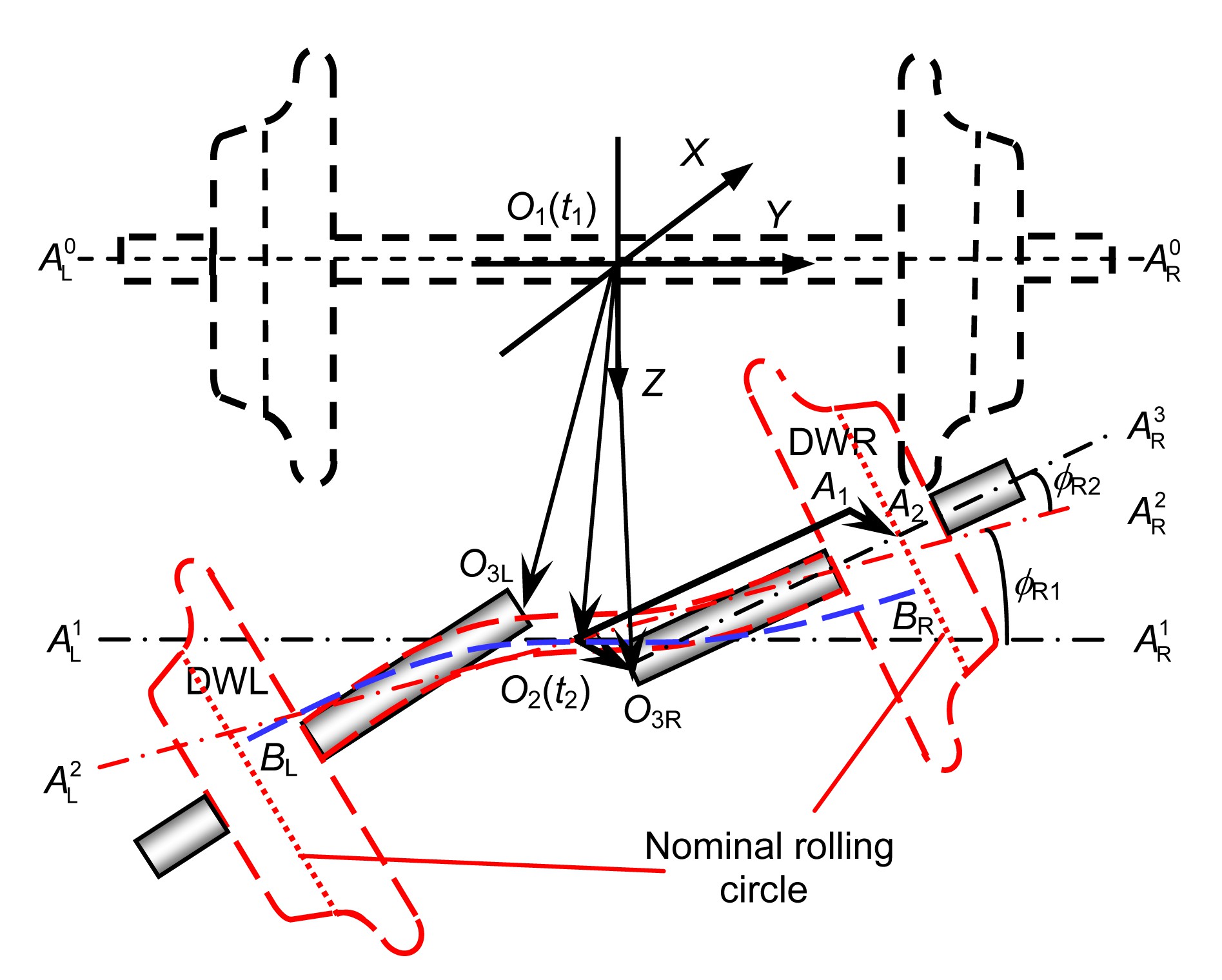
To clearly describe the new wheel-rail contact model, the dummies of the two rigid half wheelsets, as shown in Fig. 8, are employed to describe wheel-rail rolling contact behavior affected by the wheelset bending. The two dummies are indicated by DWL and DWR, respectively, and the wheels of the DWL and the DWR are assumed to overlap the left and right wheels of the flexible wheelset, respectively, all the time, namely, the motion of the assumed rigid wheels of the flexible wheelset can be described by the DWL and the DWR (Fig. 8). ϕR2 is the roll angle of the right wheel due to the bending deformation of the flexible wheelset. It is exactly the included angle between the line and the axle line of the right wheel or the wheel of the DWR.
Fig.8 The relationship between the two rigid half-wheelset dummies and the flexible wheelset
It is not difficult to calculate the wheel-rail contact geometry considering the effect of the flexible deformation of the wheelset or the local high-frequency deformations of the wheels if the spatial positions of the DWL and the DWR are determined. Determining the spatial positions of the DWL and the DWR involves calculating their motion parameters, such as the lateral displacements of the centers of the wheels of the DWL and the DWR, indicated by yDWL and yDWR, respectively, the vertical displacements, zDWL and zDWR, the roll angles, ϕDWL and ϕDWR, and the yaw angles, ψDWL and ψDWR. These parameters are key to calculating the contact geometry of the flexible wheelset in rolling contact with a pair of rails by using this new wheel-rail contact model. This will now be demonstrated in detail.
Fig. 8 describes the motion of the DWL and the DWR influenced by the wheelset bending and its rigid motion in the O-YZ plane only. After the rigid wheelset moves with the center displacement of O1O2 and the rolling angle of ϕR1 in the O-YZ plane of the global reference, O-XYZ, its center position O1(t1) reaches the position O2(t2) and reaches (or becomes) . Note that the vector O1O2 and the roll angle ϕR1 around axis X are described in the O-YZ plane. The dash-dot line is through point O2(t2) and parallel to . From Fig. 6, it is obvious that the rolling angle of the DWR caused by the wheelset rigid motion is just ϕR1, and that caused by the wheelset bending deformation is ϕR2, so the total rolling angle of the DWR is ϕDWR=ϕR1+ϕR2, as shown in Fig. 6.
In addition, the displacement of the DWR is the vector O1O3R, which could be written as
.
In Fig. 8, the vector O2A1 is parallel to O3RA2 with the same length l0. l0 is actually the distance between the center of the wheel nominal circle and the center of the un-deformed wheelset. The vector O2O3R is parallel to A1A2, with the same length. Thus, O1O3R can be written as
.
Moreover, the vector O2A1 is described by {x1y1z1}[i j k]T in O-XYZ, and can be obtained by rotating the vector {0 l0 0}[i j k]T (coinciding with the line ) about the X-axis by ϕDWR. O2A1 is written as
.
The curve (Fig. 6) is the deformed axle center line of the wheelset, which does not consider the influence of the rotation caused by the wheelset rigid motion. The point BR is the center of the right nominal circle. The axle center line () of the deformed wheelset, can be obtained by rotating about the X-axis by ϕR1. According to the definition of the curve , the vector O2BR is defined as
,
where {Δx2 Δy2 Δz2}[i j k]T is the displacement vector of the center of the right nominal circle due to the axle bending. Then the vector O2A2 is defined as {x3y3z3}[i j k]T, and can be written as
,
which is obtained according to the relationship between and , or obtained by rotating by ϕR1. The wheelset center displacement vector O1O2 is defined as {x0y0z0}[i j k]T.
Substituting Eqs. (28) and (30) and the expression of O1O2 into Eq. (27), the vector O1O3R can be written as
Similarly, when considering the wheelset bending deformation in the plane O-XY, the vector O1O3R should be given as
where ψR1 and ψR2 are the yaw angles caused by the rigid motion and the bending deformation in the plane O-XY, respectively.
ψDWR=ψR1+ψR2 is the total yaw angle of the DWR. Similarly, the position of the DWL can be obtained. When the positions of the two dummies are known at t2, the wheel-rail contact geometry can be calculated. Then the positions of the wheel-rail contact points are easily found and the wheel-rail contact forces can be calculated. The normal wheel-rail contact forces are calculated by the Hertzian nonlinear contact spring model, and the tangent contact forces and spin moments are calculated by means of the model by Shen et al. (1983). Compared with the conventional wheel-rail contact model (Wang, 1984; Zhai, 2007), this new wheel-rail contact model can characterize the independent high-frequency deformations of the two wheels of the flexible wheelset more conveniently.
3. Results and discussion
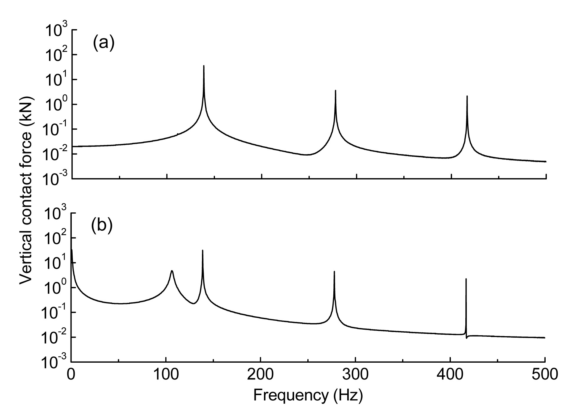
When a vehicle is running on an ideal track, it is only excited by sleepers. Note that the “flexible” wheelset model used in this section denotes the model considering the first two bending modes. The dynamic system with flexible wheelset models is used in the simulation on an ideal track at the speed of 300 km/h. Figs. 9a and 9b show the vertical forces in the frequency domain in steady and unsteady stages, respectively. In the unsteady stage, the peaks appear not only at a set of harmonic frequencies nfs (n=1, 2, 3, …) produced by passing sleeper but also at fb1, while the influence of the second bending mode is small since there is no peak at fb2. In the steady stage, the contribution of the component at fb1 is weakened and only the peaks at nfs (n=1, 2, 3, …) remain. These results are reasonable because when a system comes to a steady stage, its responses only contain the component at the excitation frequency.
Fig.9 The vertical contact force in steady (a) and unsteady (b) stages
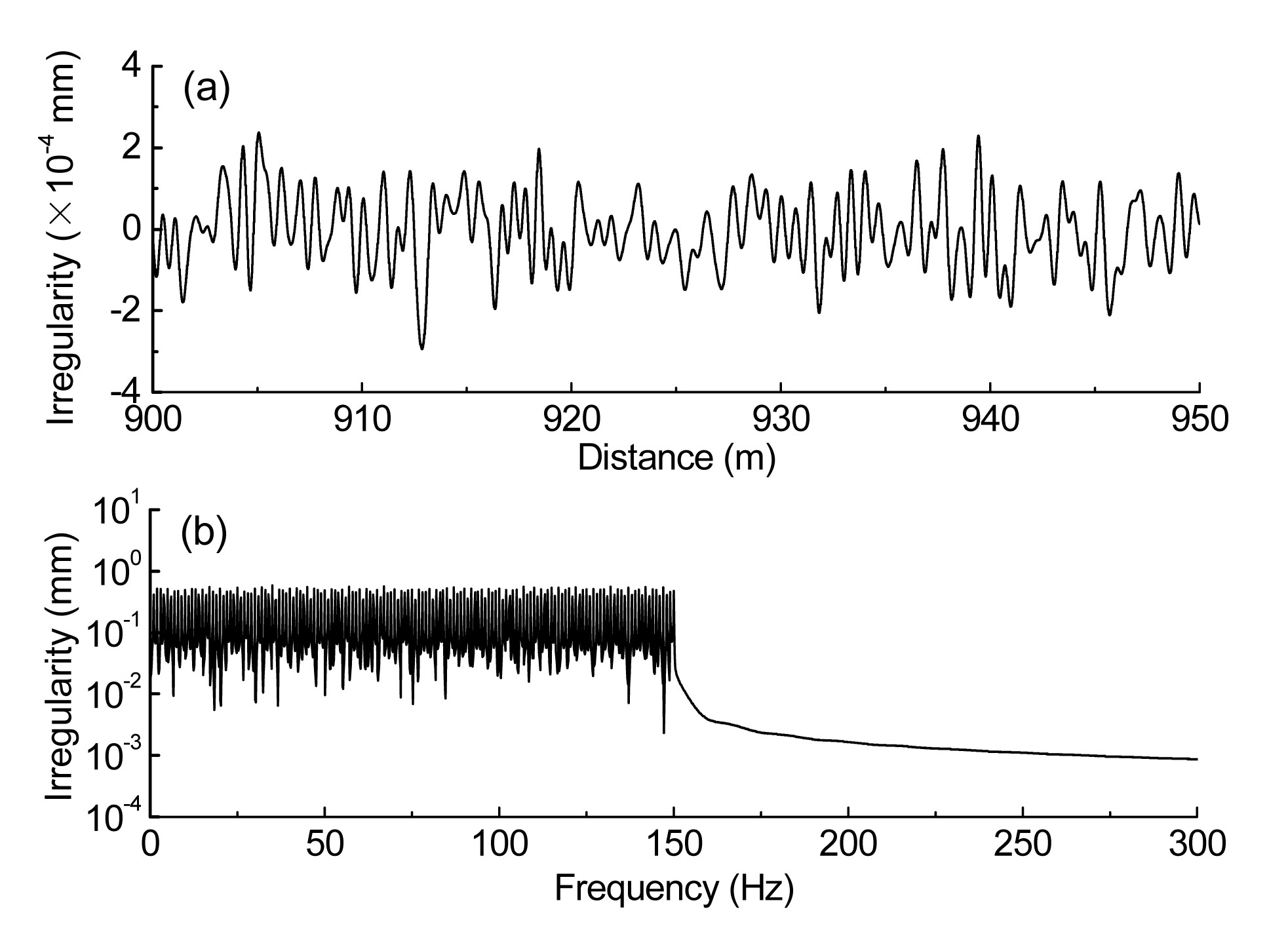
Based on a large range of site measurements, the components of roughness on rails mostly appear in the range of 1–20 m. The natural frequencies of the first two bending modes are below 250 Hz, meaning the available frequency of this model is limited. Therefore, the components of the random irregularity on the rails are mainly in the frequency range of 0–150 Hz at the speed of 300 km/h. Fig. 10a presents the local section of 900–950 m in the time domain, and Fig. 10b shows the irregularity in the frequency domain. Note that the results below are from the steady stage.
Fig.10 Random irregularity in the time domain (a) and frequency domain (b)
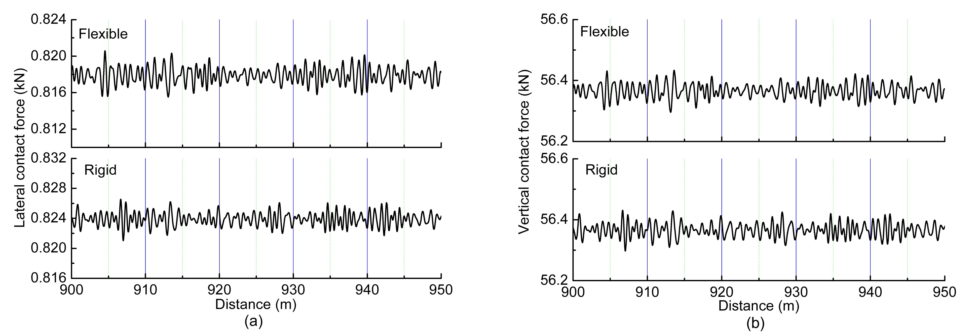
Figs. 11 and 12 show the wheel-rail contact forces acting on the rigid and flexible wheelsets in the time and frequency domains, respectively. As shown in Fig. 11a, the average of the oscillation of the lateral contact force acting on the flexible model is a little smaller than that on the rigid wheelset model, and the shapes of the oscillation are different. As shown in Fig. 11b, the vertical contact forces acting on the two models oscillate around a similar average, while their shapes are different. These differences are caused by the wheelset flexibility.
Fig.11 Lateral contact forces (a) and vertical contact forces (b) in the time domain
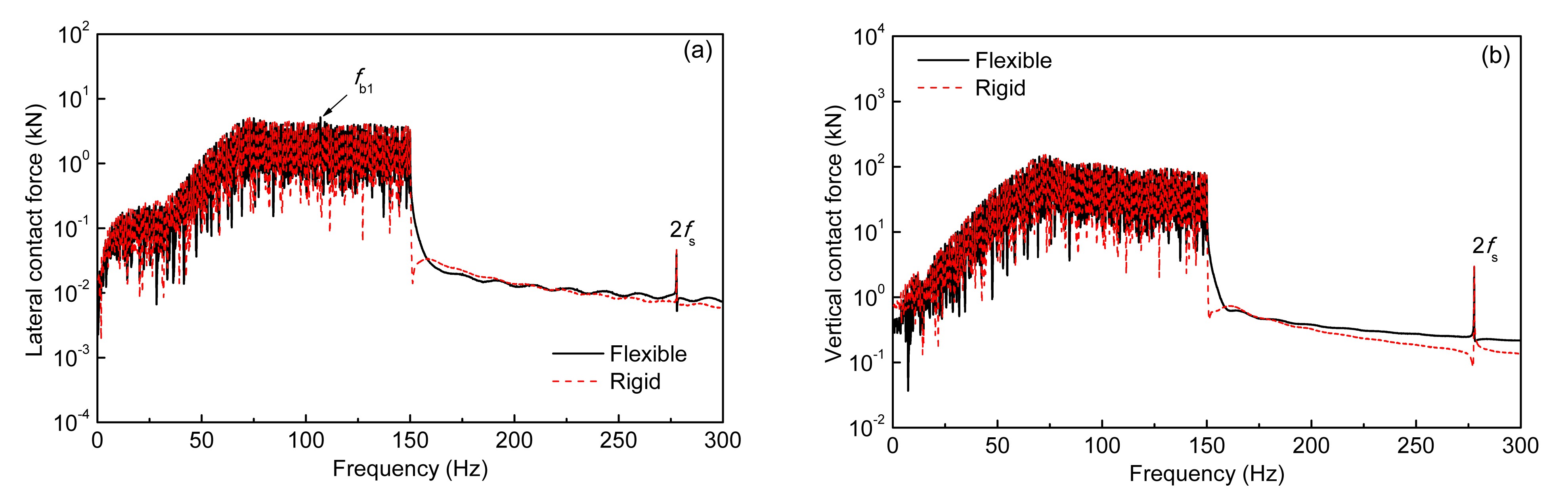
In the frequency domain, the distributions of the components contained in both the lateral and vertical contact forces are in the excitation frequency range of the random irregularity. A peak at frequency 2fs appears in Figs. 11a and 11b. The contribution of the component at frequency fs is overwhelmed by the effect of the irregularity. In addition, the uniform distribution in 0–150 Hz of the irregularity results in the non-uniform distribution of contact forces. As shown in Figs. 12a and 12b, the components in 80–150 Hz are higher than those in 0–80 Hz. This shows that under this present irregularity, this dynamic system is more sensitive to the excitation in 80–150 Hz than to those in 0–80 Hz.
In the frequency domain, the component at fb1 of the lateral contact force acting on the flexible model is a little larger than that on the rigid model, as marked using the arrow in Fig. 12a. This shows that the first bending mode is excited, and the availability of the model to characterize the wheelset bending is proved. However, there is no evident difference at fb1 for vertical contact forces acting on the two models. This shows that the wheelset bending deformation has a stronger effect on the lateral contact force than on the vertical contact force.
Fig.12 Lateral contact forces (a) and vertical contact forces (b) in the frequency domain
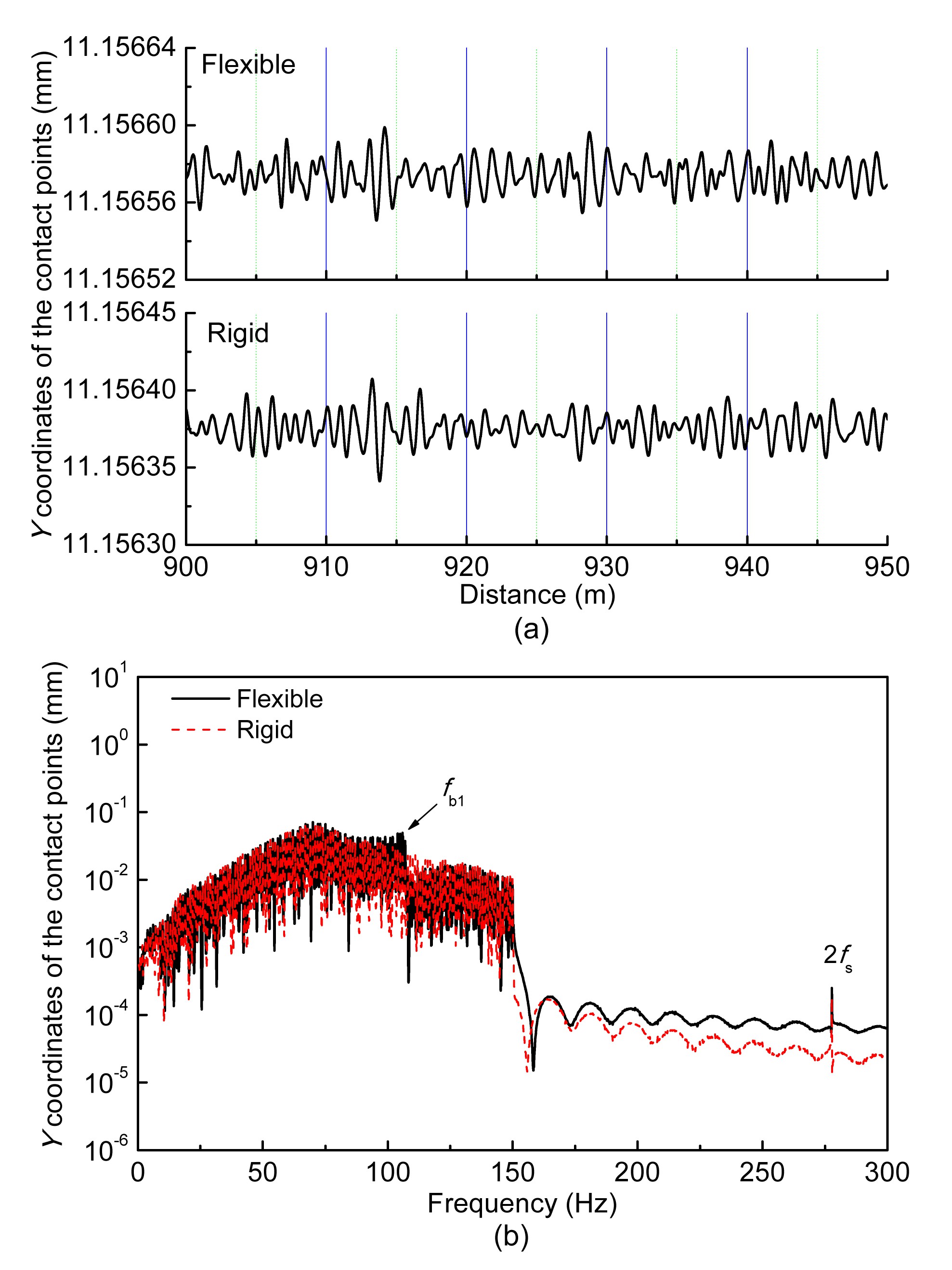
The wheel-rail contact force is affected by the position of the lateral contact points. Figs. 13a and 13b show the oscillations of the contact points in lateral direction described in the body coordinate system attached to the rail cross-section in the time and frequency domains, respectively. The average of the magnitudes of oscillation of the contact points on the flexible model in the time domain is larger than that on the rigid model. This is caused by the wheelset bending. Moreover, it can weaken the relative movement between rail and wheel caused by the irregularity. Therefore, it is one cause of the smaller average of the lateral contact force acting on the flexible model (Fig. 11a). As shown in Fig. 13b, the difference of the components between the two models at fb1 is evident. This explains the difference in the time domain (Fig. 13a) and again shows the effectiveness of the proposed model.
Fig.13 Oscillation of contact points in lateral direction in the time domain (a) and frequency domain (b)
4. Conclusions
In this study a new wheel-rail contact model is integrated into the high-speed vehicle-track coupling dynamics system model, which takes into account the effect of wheelset structural flexibility. Based on the new vehicle-track model the effect of the first two bending modes of the wheelset on wheel-rail contact behavior is analyzed under the random irregularity in a frequency range of 0–150 Hz. The numerical results of the rigid wheelset model and the flexible wheelset model are compared in detail. The following conclusions can be drawn from the results:
The present vehicle-track model considering flexible wheelsets can very well characterize the effect of the flexible wheelset on wheel-rail dynamic behavior.
Under the excitation, the shapes of the oscillations of the wheel-rail contact forces and contact points for the new and conventional vehicle-track models are different. The difference is caused by the excited first bending mode of the wheelset.
For future work, the first improvement to be considered is to model a wheelset using the FEM or the Timoshenko beam theory to broaden the model’s available frequency range. This could allow it to help investigate the mechanisms behind the generation and development of wheel-rail wear and noise.
The vehicle notations and track parameters are given in Table A1.
References
[1] Andersson, C., Abrahamsson, T., 2002. Simulation of interaction between a train in general motion and a track. Vehicle System Dynamics, 38(6):433-455.
[2] Baeza, L., Vila, P., Rodaa, A., 2008. Prediction of corrugation in rails using a non-stationary wheel-rail contact model. Wear, 265(9-10):1156-1162.
[3] Baeza, L., Vila, P., Xie, G., 2011. Prediction of rail corrugation using a rotating flexible wheelset coupled with a flexible track model and a non-Hertzian/non-steady contact model. Journal of Sound and Vibration, 330(18-19):4493-4507.
[4] Chaar, N., 2007. Wheelset Structural Flexibility and Track Flexibility in Vehicle/track Dynamic Interaction. PhD Thesis, Royal Institute of Technology,Stockholm, Sweden :
[5] Fayos, J., Baeza, L., Denia, F.D., 2007. An Eulerian coordinate-based method for analysing the structural vibrations of a solid of revolution rotating about its main axis. Journal of Sound and Vibration, 306(3-5):618-635.
[6] Jin, X.S., Xiao, X.B., Ling, L., 2013. Study on safety boundary for high-speed train running in severe environments. International Journal of Rail Transportation, 1(1-2):87-108.
[7] Kaiser, I., Popp, K., 2006. Interaction of elastic wheelsets and elastic rails: modeling and simulation. Vehicle System Dynamics, 44(S1):932-939.
[8] Meinders, T., Meinker, P., 2003. Rotor dynamics and irregular wear of elastic wheelsets, system dynamics and long-term behavior of railway vehicles, track and subgrade. System Dynamics and Long-term Behaviour of Railway Vehicles, Track and Subgrade, 6:133-152.
[9] Nielsen, J.C.O., Lundn, R., Johansson, A., 2003. Train-track interaction and mechanisms of irregular wear on wheel and rail surfaces. Vehicle System Dynamics, 40(1-3):3-54.
[10] Nielsen, J.C.O., Ekberg, A., Lundn, R., 2005. Influence of short-pitch wheel/rail corrugation on rolling contact fatigue of railway wheels. Journal of Rail and Rapid Transit, 219(3):177-188.
[11] Popp, K., Kruse, H., Kaiser, I., 1999. Vehicle/track dynamics in the mid-frequency range. Vehicle System Dynamics, 31(5-6):423-463.
[12] Popp, K., Kaiser, I., Kruse, H., 2003. System dynamics of railway vehicles and track. Archive of Applied Mechanics, 72(11-12):949-961.
[13] Qiu, J.B., Xiang, S.H., Zhang, Z.P., 2009. Computational Structural Dynamics. (in Chinese), Press of University of Science and Technology of China,Hefei, China :
[14] Shen, Z.Y., Hedrick, J.K., Elkins, J.A., 1983. A comparison of alternative creep force models for rail vehicle dynamic analysis. Vehicle System Dynamics, 12(1-3):79-83.
[15] Szolc, T., 1998. Medium frequency dynamic investigation of the railway wheelset-track system using a discrete-continuous model. Archive of Applied Mechanics, 68(1):30-45.
[16] Szolc, T., 1998. Simulation of bending-torsional-lateral vibrations of the railway wheelset-track system in the medium frequency range. Vehicle System Dynamics, 30(6):473-508.
[17] Torstensson, P.T., Nielsen, J.C.O., 2011. Simulation of dynamic vehicle-track interaction on small radius curves. Vehicle System Dynamics, 49(11):1711-1732.
[18] Torstensson, P.T., Pieringer, A., Nielsen, J.C.O., 2012. Simulation of rail roughness growth on small radius curves using a non-Hertzian and non-steady wheel-rail contact model. , 9th International Conference on Contact Mechanics and Wear of Rail/Wheel Systems, Chengdu, China, 223-230. :223-230.
[19] Wang, K.W., 1984. Wheel contact point trace line and wheel/rail contact geometry parameters computation. Journal of Southwest Jiaotong University, (in Chinese),1:89-99.
[20] Xiao, X.B., Jin, X.S., Wen, Z.F., 2007. Effect of disabled fastening systems and ballast on vehicle derailment. Journal of Vibration and Acoustics, 129(2):217-229.
[21] Xiao, X.B., Jin, X.S., Deng, Y.Q., 2008. Effect of curved track support failure on vehicle derailment. Vehicle System Dynamics, 46(11):1029-1059.
[22] Xiao, X.B., Jin, X.S., Wen, Z.F., 2010. Effect of tangent track buckle on vehicle derailment. Multibody System Dynamics, 25(1):1-41.
[23] Zhai, W.M., 2007. Vehicle/Track Coupling Dynamics (3rd Edition). (in Chinese), Chinese Science Press,Beijing, China :
[24] Zhong, S.Q., Xiao, X.B., Wen, Z.F., 2013. The effect of first-order bending resonance of wheelset at high speed on wheel-rail contact behavior. Advances in Mechanical Engineering, 2013:296106
[25] Zhong, S.Q., Xiao, X.B., Wen, Z.F., 2014. A new wheel-rail contact model integrated into a coupled vehicle-track system model considering wheelset bending. , 2nd International Conference on Railway Technology Research, Development and Maintenance, Ajacocia, France, 1-10. :1-10.
Open peer comments: Debate/Discuss/Question/Opinion
No where forces values are given ,Like if a 31Tonne axle load running at 300km/hr then at what force track will experiencing in longitudinal direction,vertical direction, thrust which over turn track?


 ORCID:
Open peer comments: Debate/Discuss/Question/Opinion
<1>
Ramesh<rcdohare@gmail.com>
2016-12-28 17:32:30
No where forces values are given ,Like if a 31Tonne axle load running at 300km/hr then at what force track will experiencing in longitudinal direction,vertical direction, thrust which over turn track?