Zhi-gang Shan, Sheng-jie Di. Loading-unloading test analysis of anisotropic columnar jointed basalts[J]. Journal of Zhejiang University Science A, 2013, 14(8): 603-614.
@article{title="Loading-unloading test analysis of anisotropic columnar jointed basalts", author="Zhi-gang Shan, Sheng-jie Di", journal="Journal of Zhejiang University Science A", volume="14", number="8", pages="603-614", year="2013", publisher="Zhejiang University Press & Springer", doi="10.1631/jzus.A1200261" }
%0 Journal Article %T Loading-unloading test analysis of anisotropic columnar jointed basalts %A Zhi-gang Shan %A Sheng-jie Di %J Journal of Zhejiang University SCIENCE A %V 14 %N 8 %P 603-614 %@ 1673-565X %D 2013 %I Zhejiang University Press & Springer %DOI 10.1631/jzus.A1200261
TY - JOUR T1 - Loading-unloading test analysis of anisotropic columnar jointed basalts A1 - Zhi-gang Shan A1 - Sheng-jie Di J0 - Journal of Zhejiang University Science A VL - 14 IS - 8 SP - 603 EP - 614 %@ 1673-565X Y1 - 2013 PB - Zhejiang University Press & Springer ER - DOI - 10.1631/jzus.A1200261
Abstract: To evaluate the columnar jointed basalts in the dam site of Baihetan hydropower station in southwest China, we developed a basic conceptual model of single jointed rock mass. Considering that the rock mass deformation consists of rock block deformation and joints deformation, the linear mechanical characteristics of the cell (including the elastic joints and the nonlinear mechanical behaviors of the cell) with a combined frictional-elastic interface were analyzed. We developed formulas to calculate the rock block deformation, which can be adapted for multiple jointed rock mass and columnar jointed basalts. The formulas are effective in calculating the equivalent modulus of multiple jointed rock mass, and precisely reveal the anisotropic properties of columnar jointed basalts. Furthermore, the in situ rigid bearing plate tests were analyzed and calculated, and the types of loading-unloading curves and the equivalent modulus along different directions of columnar jointed basalts were obtained. The analytical results are in close compliance with the test results.
Darkslateblue:Affiliate; Royal Blue:Author; Turquoise:Article
Article Content
1. Introduction
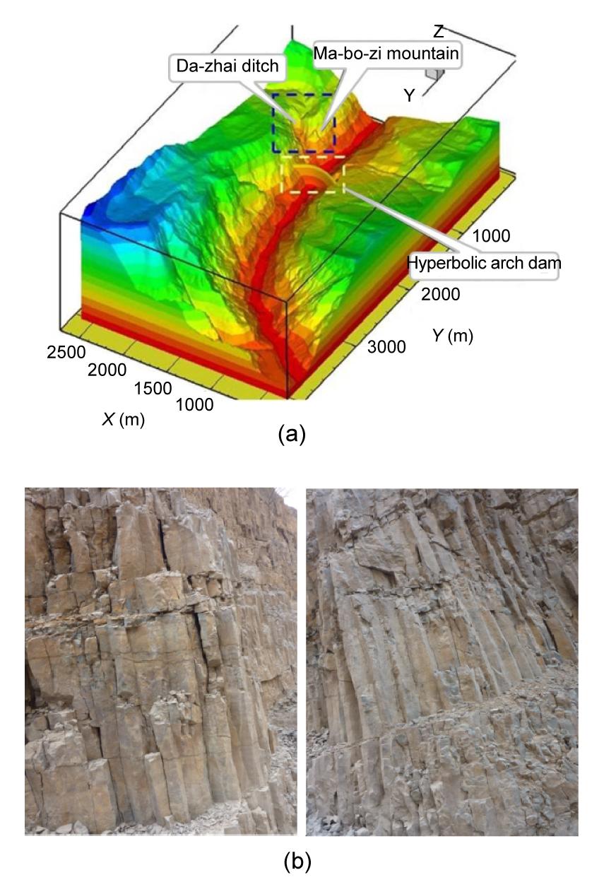
Columnar jointed basalts are the typical type of rock mass materials generated after the condensation of volcanic lava. They are widespread in nature and frequently encountered in civil and hydraulic engineering. For example, the Baihetan hydropower station in southwest China is located in an area containing columnar jointed basalts (Fig. 1). This ten million kW-level hydropower plant will represent the main power supply point for the west-to-east power transmission project in China. The dam foundation and dam abutment are located at an area where columnar jointed basalts are highly developed, leading to anisotropic properties, in which measurements in different directions can produce different values. This unique feature has attracted the attention of many domestic and foreign experts who are conducting in situ geological investigations.
Fig.1 Visual model of Baihetan hydropower station (a) and columnar jointed basalts (b)
According to the traditional classification of engineering geological quality, columnar jointed basalts belong to the group of rock masses with poor integrity. Therefore, the question of whether it can meet the strict deformation requirements of a high-arch dam foundation has drawn wide attention in the engineering field. To investigate the geometric features and engineering properties of basalts, the Basalt Waste Isolation Project (BWIP) conducted simulation-based calculations of columnar jointed basalts using regular hexagons (Hart et al., 1985). An analysis was made concerning the foundation settlement of the skyscraper in Tenerife Island, where columnar jointed basalt was discovered (Justo et al., 2006). Schultz (1996) evaluated the engineering quality of this polycrystalline rock mass and estimated its deformation and strength parameters. However, previous studies did not evaluate the effects of irregular shape distribution of columns’ cross sections. Columnar jointed basalts are generally considered to be discontinuous materials, and deformation and strength properties differ significantly from those of continuum materials.
As the need for construction in columnar jointed basalt areas increases, the corresponding research is being conducted. Based on geological characteristics of columnar jointed basalts in the Baihetan hydropower station, the factors that influenced the deformation performance of these basalts are introduced and explained (Shi et al., 2008), and the Voronoi method to describe the geological structure of columnar jointed basalt were used in simulation studies. Mathematical and mechanical methods were also used in studying the anisotropic behavior of columnar jointed basalts, as well as the constitutive relation, parameter values, and yield criterion. The references is well-applied in the project of the Baihetan hydropower station (Meng, 2007; Zheng, 2008; Xu et al., 2010; 2011a; 2011b; Di et al., 2011; Yan et al., 2011). Deformation mechanical behavior of discontinuous medium is studied. In consideration of dilatancy phenomena and slip and sliding effects, a new interface constitutive model was adopted to simulate the joints, masonry, or concrete-cracked interfaces under monotonic and cyclic loading (Mroz and Giambanco, 1996). Simplified analysis of interface failure under compressive normal stress and monotonic or cyclic shear loading produced encouraging results (Mroz and Bialas, 2005). Felice and Amorosi (2010) made elastoplastic analysis of block structures through a homogenization method, regarded the regular jointed rock mass at a macroscopic scale as homogenized anisotropic media, and provided references for investigation on anisotropic mechanical properties of columnar jointed basalts. Sharma et al. (1989) recommended a flexible bearing plate test to reveal a deformation modulus of jointed rock mass. Tsanga et al. (2005) simulated random fractures in the rock mass as part of the DECOVALEX III and BENCHPAR projects. They performed several numerical tests using universal distinct element code (UDEC), and studied the size of the representative elementary volume (REV) and the equivalent mechanical parameters. Palmstrom and Singh (2001) stated that the loading-unloading test curve should not be included in the calculation of the integral deformation modulus, and they also conducted theoretical research about the deformation modulus of jointed rock mass. Brady et al. (1985) precisely analyzed the loading-unloading regularity of large-size columnar jointed basalts, and discovered three typical mechanical behaviors for different phases. They adopted a theoretical analysis of in situ testing simulation to discuss several problems concerning the joint stiffness, loading-unloading behavior of single jointed rock mass, anisotropic properties of multiple jointed rock mass, and simulation on random models of columnar jointed basalts.
Because of the specific distribution of the structural plane in jointed rock mass, it represents complicated mechanical characteristics of discontinuity, nonuniformity, and anisotropy. It differs from continuum on both strength and deformation, which means that the method of continuum theory is not applicable. Jointed rock mass is a component of rock block and distributed joints; hence, rock block and structural plane superposition methods can be used to calculate the deformation of rock mass. As the existing method and in situ test method cannot reveal the anisotropic properties of jointed rock mass from mechanical essence, it is necessary to start with the fundamental principle of rock mass mechanics. With a deep understanding of mechanical properties of joints and macro-deformation law of rock mass, the anisotropic characteristics of columnar jointed basalts can be comprehended.
The main advantage of the theory of single-weak surface rock mass is its approach to explaining the phenomenon of discontinuous jointed rock mass deformation and destruction. To evaluate the basic mechanical analysis of single jointed rock mass, this paper studied its elastic deformation and loading-unloading hysteretic characteristics. Then the specific formula of jointed rock mass deformation was derived, and then extended into rock mass with multiple random joints. By comparing the analytical results with in situ test results, the method in this study provided instructive references for engineers.
2. Conceptual model of single jointed rock mass
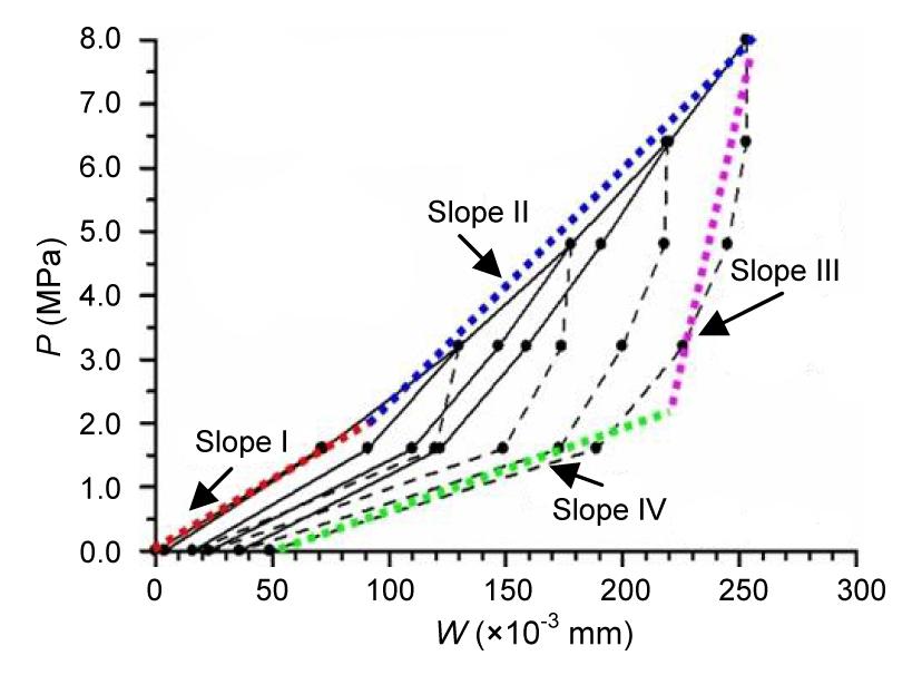
The description concerning the typical loading-unloading curves of columnar jointed basalts is as shown in Fig. 2. The loading-unloading curve during the initial phase of loading should not be included in the calculation of integral deformation modulus because the experiment point was subjected to the influence of excavation blasting. Therefore, joints were tight and close at this stage, but did not represent the state of undisturbed rock mass.
Fig.2 Typical loading-unloading curves of columnar jointed basalts Slope I: compression stage; Slope II: linear deformation stage; Slope III: initial unloading phase; Slope IV: later unloading phase
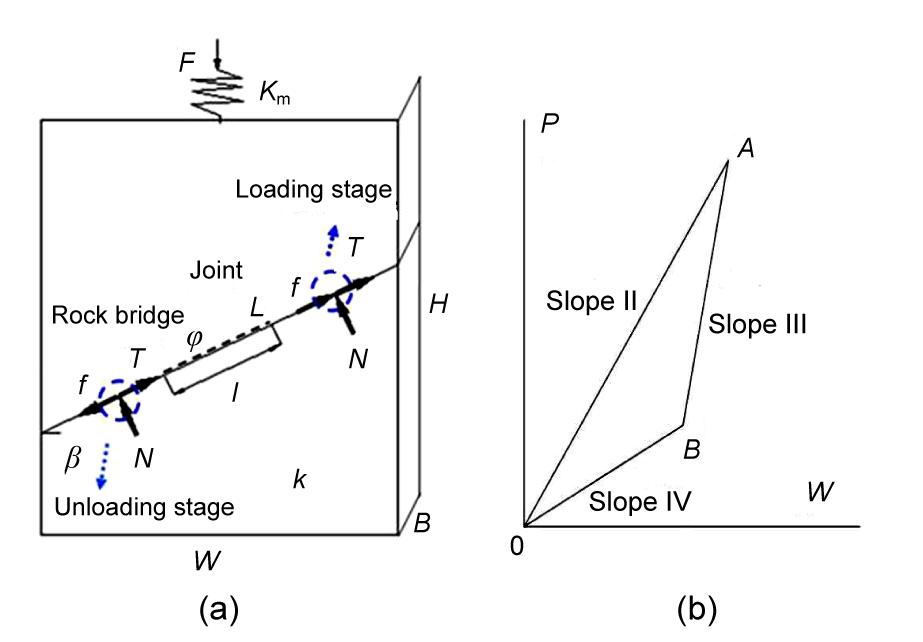
Complex jointed rock mass behaved according to the pattern mentioned above; thus, the study of single jointed rock mass should be conducted so as to fully understand the mechanical properties of this type of rock mass. For a rock mass with only one closed joint for analysis, the conceptual model is shown in Fig. 3a. The mechanical parameters are as follows: krn and krs are the compression and shear stiffness of rock block, E is the elastic modulus of rock block, k is the integral equivalent stiffness of rock mass, β is the angle between the normal direction of joint surface and the loading direction, Kjn and Kjs are the normal and tangential stiffness of join, φ is the friction angle of joint, l is the length of closed joint, and L−l is the length of rock bridge. The stress distributions and deformation characteristics of jointed rock mass are very complicated; nevertheless, the conceptual model can capture the essence of the issue and can reveal the mechanical properties of rock mass.
Fig.3 Conceptual model of single jointed rock mass and cyclic loading curve (a) Conceptual model (W is the length, B is the width, and H is the height); (b) Loading-unloading curve of single jointed rock mass. Slope II represents the loading stage, Slope III the initial unloading stage, and Slope IV the subsequent unloading stage of P-W curve
Suppose the rock block is an ideal elastic material, i.e., the value of joint stiffness does not vary with the change of stress, and the stress condition of the rock mass is the same as that of rock block. When the rock mass generated the smaller deformation, the loading was not big enough to overcome the boundary constraints and friction-locking strength between joint surfaces, and the essential relative sliding did not occur. The shear and compression deformation of joint surface was totally recoverable and elastic, namely, a cell with elastic joints, which was applied to the conditions of smaller deformation, smaller loading, higher geostress, and harder rock mass. If the initial compression phase of the rock mass was omitted, for simplicity, the loading-unloading curve of single jointed rock mass is as shown in Fig. 3b.
The axial displacement of jointed rock mass along the loading direction is composed of three parts, which can be expressed as u=urn+ujs+ujn, and the stiffness satisfies the following equation:
,
where urn, ujs, and ujn represent respectively the deformation of the rock block, the tangential displacement of joint, and normal displacement of joint along the load direction. kjn and kjs are the factors of the normal and tangential stiffness of joints (Kjn and Kjs ) along the load direction. kj stands for the relation of force and displacement with a unit of N/m, while Kj stands for the relation of stress and deformation with a unit of N/m3. The deformations of jointed rock mass along the loading direction are calculated by
,
,
.
The corresponding stiffness are
,
,
.
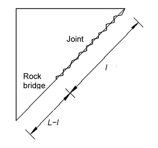
As for a discontinuous joint, without considering factors such as the stress concentration at contact part of the rock bridge and joint, the modification can be made to Eqs. (5)–(7). When the joint is discontinuous, the length of trace line L means the sum of the lengths of the joint l and the rock bridge (L−l) along the joint direction. The connectivity rate of joint is defined as 0<η=l/L<1 (Fig. 4), where η means the connection rate of discontinuous joint, which is the percentage of the length of joint from the length of the rock bridge. As the mechanical properties of the discontinuous joint are complex, the equivalent joint stiffness and can be adopted and considered as the superposition of the rock block and joint stiffness.
Fig.4 Media with non-interpenetrated joint
When both of the rock bridge and joint are taken into account, the equivalent stiffness and can be expressed as
,
,
where Krn and Krs represent the compression of rock block and joints, which can be measured through the pressure-shear test in laboratory. This allows for ease in calculation of the equivalent deformation of discontinuous jointed rock mass, by introducing the concepts of and . As a more general method for a discontinuous joint, Eqs. (8) and (9) can replace Kjn and Kjs in Eqs. (2) and (3), resulting in
,
.
When the joints are continuous in the rock mass, and in Eqs. (10) and (11) can be degenerated into the stiffness of joints.
As the load gradually increases until it overcomes the boundary constraints and joint friction locking strength of the model, the relative sliding trend between the joint surfaces occurs. At this point, a combined frictional-elastic interface can be specified. When the load is small, the deformation is elastic, and the deformation will be back to the point of origin after unloading (Fig. 2). In other words, the larger the load, the bigger the hysteresis loops, the joint effects, and the energy absorption. Ideally, the cells with elastic joints and combined frictional-elastic interface can be viewed as two different mechanical behaviors of jointed physical model under different situations.
The combined frictional-elastic interface can be analyzed, and the loading phase should meet the following relationship:
,
,
,
,
where T is the tension generated at the top of joints, N represents the normal force of equivalent continuous joint, f is the frictional resistance along the joint surface, is the deformation of joints along the joint surface, and u′ is the total axial deformation of rock mass with consideration of joint deformation.
The curve slope of the loading phase can be deduced by substituting Eq. (14) into Eq. (15):
.
When the vertical load is removed at a certain rate, the jointed rock mass generates an inverse resilience. If the frictional resistance is strong enough to stop the joint surface from sliding upward, the displacement only represents the deformation of rock mass without the slip value of joints. Then Slope III =k/(BW), simultaneously the unloading stage can be described as follows:
,
.
If the model is considered as a square with unit length, then the slopes can be derived as
,
,
.
The elastic parameter k (containing joint stiffness kj and rock block stiffness kr, as shown in Eq. (1)) is included in Eqs. (12)–(21) of the calculation method of combined frictional-elastic interface. The method includes the calculation method of elastic joints cell. Eqs. (1)–(7) of elastic joints are the foundation of deducing Eqs. (12)–(21). The inclination angle of columnar jointed basalt is generally between 70° and 80°, thus Slope IV With existence of non-linear mechanical behavior on joint surface, its loading-unloading curve represents a hysteresis effect, which indicates an unreversed deformation. This means that the conceptual model can reflect the results of bearing plate tests. For loading-unloading tests of multiple jointed rock mass, the results in the initial unloading phase are shown by an unloading curve with a declining slope. Only at the initial unloading phase could the non-elastic deformation of the joint be inhibited, which reveals authentic elastic mechanical behavior of jointed rock mass.
As the loading is normally under the yield stress of rock block, the hysteresis effect is likely caused by nonlinear mechanical behavior of joints. The loading-unloading curves showed that the typical up-concave curve reflects the trend of increasing modulus when structural surface is compressed by augmented stress. Linear and up-convex curves represent the properties of linear elastic rock block and initial strength of rock mass, respectively. However, the slope of the curve decreases significantly when the rock mass is unloaded at low stress. This explains that the fractures are loose under the effect of unloading.
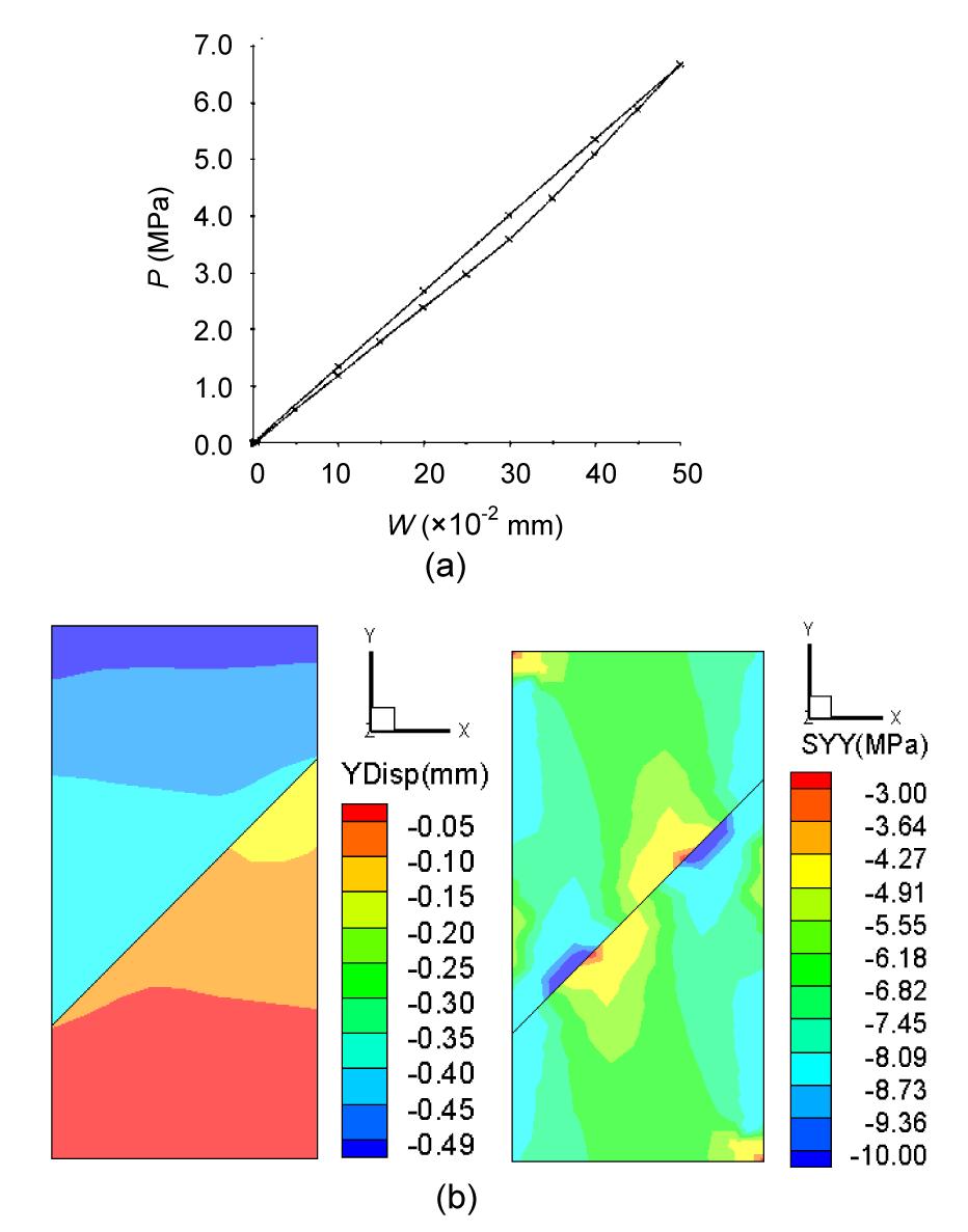
The fact that the rigid bearing plate test of jointed rock mass displayed a hysteresis effect is due to the existence of internal fractures network and joints. To verify the theoretical method, a conceptual model of single jointed rock mass was created using the finite element method. The rock block was assumed to be equivalent-continuum, and its mechanical parameter was stable regardless of change of stress. A stiffness of 20 GPa/m was set to observe the effect. With the numerical simulation, the loading-unloading curve and diagram of stress distribution were obtained (Fig. 5). The curve had a little hysteretic loop resulting from the joint, and this also caused discontinuous stress and deformation at joints. The slopes of the curve are highly consistent with analytical results.
Fig.5 Loading-unloading curve of single jointed rock mass (a) and diagram of vertical displacement and stress (b)
3. Anisotropic properties of elastic deformation
If the rock block was an ideal elastic material, stiffness of the joint would not vary with change of stress. The stress condition of the rock mass was the same as that of the rock block. This is applicable for those compact basalts with large stiffness. For rock mass of a certain scale, the superposition method can help to estimate the total deformation of multiple jointed rock mass along its loading direction. It meets the following equations, based on Eqs. (1)–(7) using the cell with elastic joints:
.
The deformation of rock mass with a joint of length L can be given as
.
The general formula for the deformation of rock mass with random joints is
,
where m is the number of joints. For the joint element with a certain thickness, the thickness represents the distance of element. βi is the angle between the loading direction and the normal direction of the ith joint. The term Licosβi/W reflects the factors of equivalent displacement along the loading direction, known as effective length ratio. The equivalent deformation modulus of rock mass along the loading direction can be obtained as follows:
.
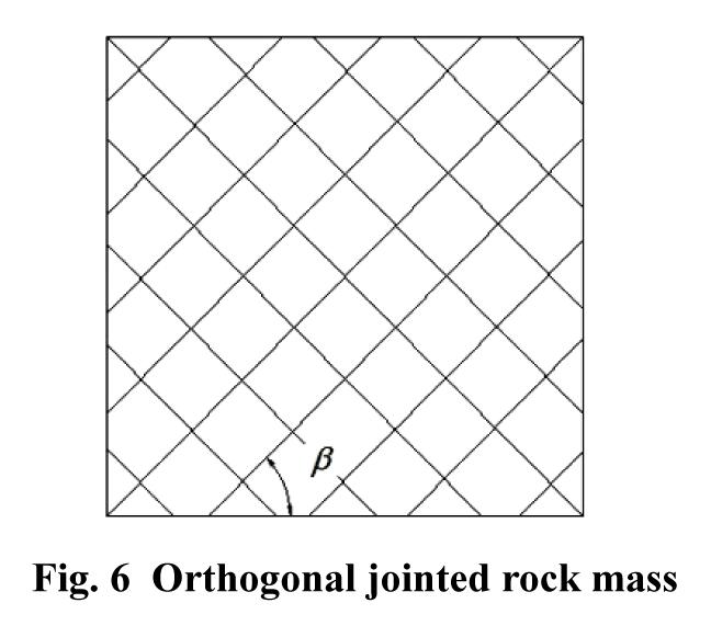
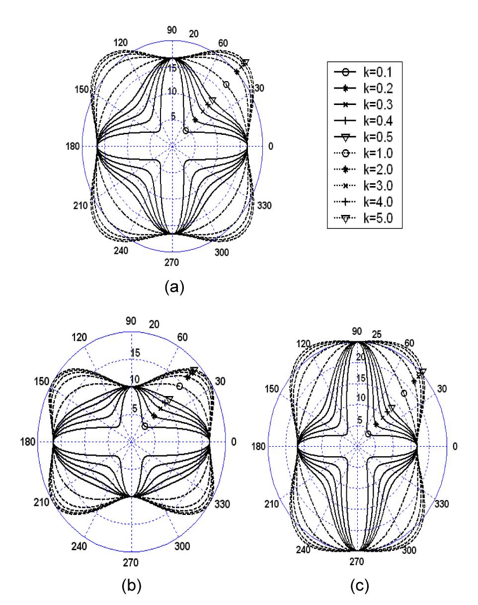
With the introduction of the angle between the loading direction and the normal direction of joints, the regularity of the deformation modulus and the anisotropic properties of columnar jointed basalts can be discovered. Assuming that the square rock mass is 10 m in length, the joints are orthogonal and have a uniform distance of 0.5 m (Fig. 6). The elastic modulus is 50 GPa, and the normal stiffness of the joint is 50 GPa/m; k is the stiffness ratio of tangential direction and normal direction, according to the equivalent elastic modulus of different joint angles (Fig. 7). Fig. 7a represents the variation of joint with k when the two orthogonal joints share the same normal stiffness and Fig. 7b and Fig. 7c represent the situations in which the normal stiffnesses of the first group are twice and half as that of the second group, respectively. The anisotropic properties of the curve corresponding to the regularity in Fig. 7 were also found by Min and Jing (2003). In addition, Eqs. (24) and (25) can also be applied to calculate the equivalent modulus of the random distributed joints in the rock mass.
Fig.6 Orthogonal jointed rock mass
Fig.7 2D graphics of anisotropic modulus curves in polar coordinates (a) Kn1/Kn2=1; (b) Kn1/Kn2=2; (c) Kn1/Kn2=0.5
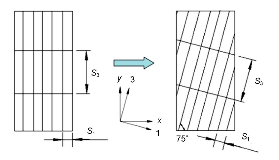
Elastic modulus increased with the decrease of the ratio of Ks/Kn, and it reached its maximum with the angle of 45º. When the two groups of joints had distinct stiffness (i.e., the horizontal stiffness was twice as large as the vertical stiffness), the graphic of modulus was oval. While the two groups of joints were equidistant and had identical stiffness, the graphic was a spherical shape. When Ks/Kn=1, although the two joints were equidistant, they had different stiffness and displayed the anisotropic characteristics. In the project of the Baihetan hydropower station, the columnar jointed basalt has the angle of 15° between the column and the principal axis. Suppose the column diameter S1 is about 20 cm, its length S3 is about 1 m and the elastic modulus has the value of 65.1 GPa. The normal stiffness and tangential stiffness of joints are respectively, 284.48 GPa/m and 99.31 GPa/m. The conceptual model can be seen in Fig. 8. The elastic moduli E3 and E1 under the main coordinate system are 53 GPa and 30.4 GPa, respectively. Ex and Ey under the coordinate system of x-y turn to be 31.6 GPa and 27.1 GPa after the deviation of 15° to the principal axis.
Fig.8 Column-deflection diagram of columnar jointed basalt 1 and 3 are perpendicular and parallel to the direction of columnar joints
4. In situ rigid bearing plate test of columnar jointed basalts
The existence of structural surface makes the transmission of force and deformation distribution complicated. The in situ rigid bearing plate tests of columnar jointed basalts were conducted in the dam site on both sides of the Jinsha River, with a total of 67 test groups. The test data included the whole deformation under all stages of loading, elastic deformation, equivalent deformation modulus, and equivalent elastic modulus (Fig. 9). Four directions of the in situ test were performed, including vertical direction, horizontal direction, parallel to the columnar direction, and perpendicular to the columnar direction.
Fig.9 Scheme of the rigid bearing plate test (a) Vertical loading; (b) Horizontal loading; (c) Parallel to column; (d) Perpendicular to column. 1: columnar joints; 2 rigid bearing plate; 3 dial indicator; 4: jack; 5: transfer column
After the test device was installed at the test point, the jack was used to exert reaction loading to the jointed rock mass. The loading-unloading had four or five stages, each stage was 2 MPa in general, and the maximum loading was about 8 MPa or 10 MPa. Each stage ended when the deformation of the columnar jointed basalts stabilized. The method of stepwise loading and unloading was adopted. For example, the loading was 2 MPa at the first load-step until the deformation was stable, and then the unload stage was 0 MPa. Afterwards, the loading of the rigid bearing plate reached 4 MPa through two stages, and then the unloading was 0 MPa through two stages. Similarly, the maximum loading and corresponding unloading were implemented at the end of the test based on this method.
The four dial gauges were laid out symmetrically in four directions of the rigid bearing plate to test the deformation of rock mass. After the loading was applied, the value of deformation was measured immediately and every ten minutes afterward the process was repeated. When two adjacent values measured from the four dial gauges differed by less than 5%, we considered that the deformation was stable.
There were more fractures existing in rock mass along the direction of the column. The rock masses were usually compressed with a low deformation modulus. The top and bottom walls were less stable than the horizontal walls in the caves at the dam site, which were also confirmed by the in situ acoustic wave test. To conclude the effect of those factors, the vertical joints stiffness has actually decreased and reduced the total deformation modulus of rock mass. According to the test results, the horizontal deformation modulus of the columnar jointed basalts was higher than the vertical one, and the obvious anisotropic mechanical characteristics were shown.
5. Classification of loading-unloading curves and comparison of equivalent modulus
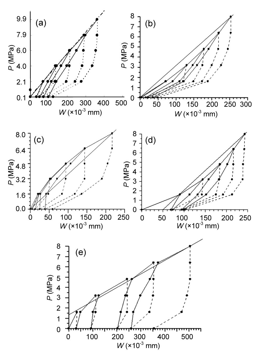
Curves resulted from rigid bearing plate test can be classified into five types: linear, up-concave curve, up-convex curve, up-concave polyline, and up-convex polyline (Fig. 10).
Fig.10 Curve types of in situ loading-unloading stress and displacement (a) Curve type A; (b) Curve type B; (c) Curve type C; (d) Curve type D; (e) Curve type E. Dashed lines represent the connection of unloadings points, and solid lines represent the connection of loading points
According to the analysis of in situ test curves, the linear curve (Fig. 10a) shows that the rock mass is comparatively integrated during the experiment. Small and short fractures are uniformly distributed; the rock mass shows the properties of approximately isotropic material under test range. The up-concave curve (Fig. 10b) represents that the superficial rock mass is crushed, and it is compressed during the loading process. This phase contributes to the increasing trend of rock mass deformation modulus. The up-convex curve (Fig. 10c) indicates that the rock mass has its initial structural strength. It has high integrity and elastoplastic global deformation. The up-concave polyline (Fig. 10d) shows that with the increasing loading stress, the deformation augmented linearly. However, the low rate of growth reveals poor rock mass behavior and small deformation modulus. The up-convex polyline (Fig. 10e) shows that the rock mass has initial structural strength or certain stress. The general deformation represents elastoplastic properties. Hence, the deformation curves can be generally classified into three types: the linear type, up-concave type, and up-convex type. They are representative of curves for elastic rock mass, compressed rock mass, and rock mass with initial strength, respectively.
The curves of different types of rigid bearing plate tests are analyzed; the values of disturbed and undisturbed joint stiffness are adopted from previous research (Di et al., 2011). Because of excavating and blasting in the caves, there are disturbed layers in the surface of the rock mass. The joint stiffness Kn and Ks in disturbed rock mass layers are 204.1 GPa/m and 69.7 GPa/m, respectively (Table 1). The joint stiffness Kn and Ks in undisturbed rock mass layers are 335.5 GPa/m and 104.1 GPa/m, respectively. The left, right, and bottom boundaries of the model are fixed. If the rock mass is regarded as an undisturbed layer, the value of joint stiffness (Kn, Ks) used in the calculation is the undisturbed (as above 335.5 GPa/m and 104.1 GPa/m). Under this condition the loading-unloading mechanical process is analyzed, and linear curves concerning stress and deformation of rock mass can be obtained.
Table 1
Irregular joint parameter
Physical and mechanical parameter of basalt
Columnar joint parameter
Er (GPa)
ri
Density (kg/m3)
Average distance of joints (m)
Friction angle (°)
Cohension (MPa)
60
0.23
2870
0.20
36
0.5×10⁶
If the initial geostress or the structure strength is considered in the rock mass, the up-convex curves in situ tested are analyzed, then confining pressure of 2 MPa or 4 MPa is applied to the boundary of the model, and the values of joint stiffness in the previous stages of loading are of the undisturbed rock mass. In view of the initial geostress being partly balanced or the structure strength being partly destroyed by continuous loading, and when the values of joint stiffness employed in calculation account for 0.5–0.7 of the undisturbed value, the slope II of the up-convex curves gradually decrease under the loading. These can be considered for the weakening coefficient effect of joints through blasting excavation, and the curves coincide well with the test results.
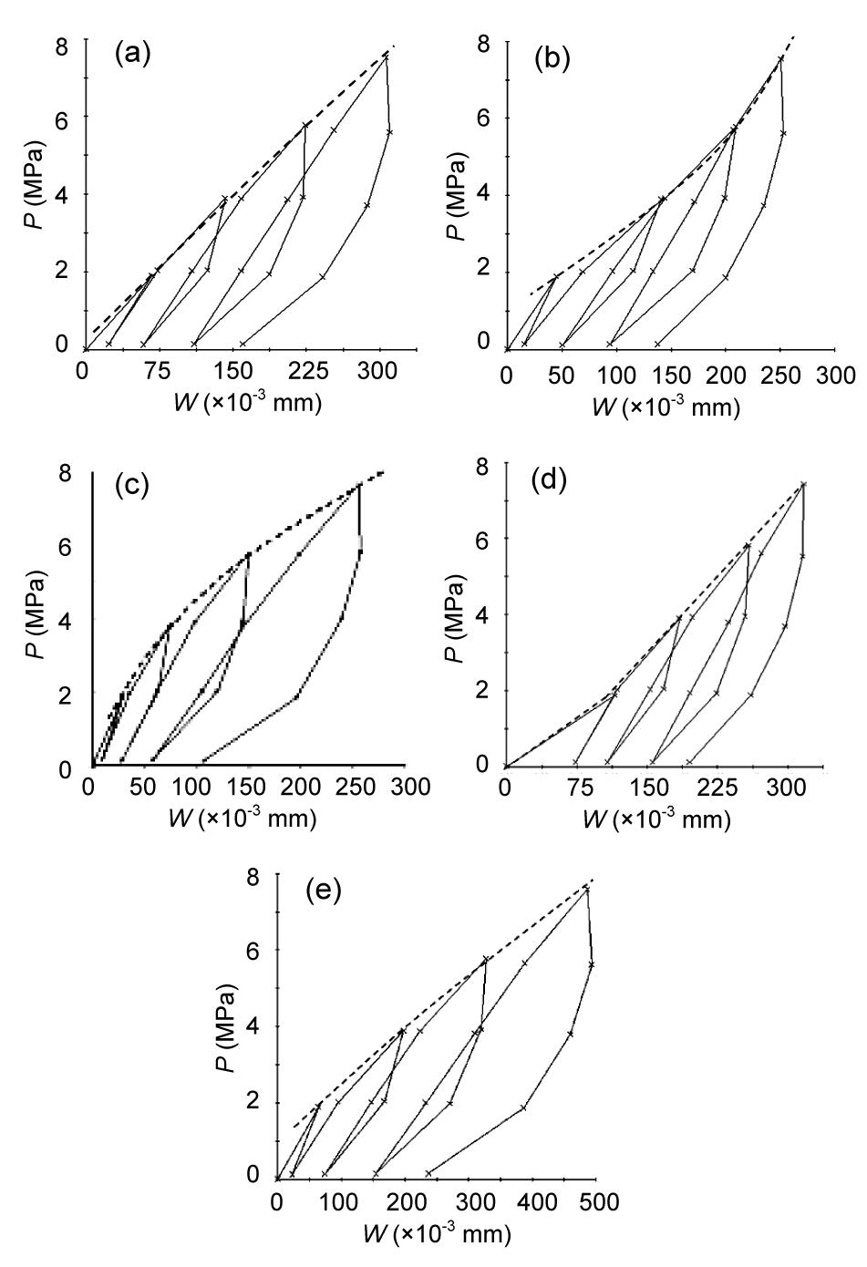
If the joints in the rock mass are looser before applying the loading, the previous stages of loading make the joints close and the rock mass compress. For this kind of rock mass, according to the in situ test results, at the previous stages of loading, the disturbed joints stiffness is used in the model. The undisturbed joints stiffness is used in the following calculation as the loading increases. Therefore, the equivalent modulus of the rock mass has a gradually increasing trend. The calculation results can confirm the mechanical properties of all types of curves in situ tested. Based on the analysis of rigid bearing plate test mentioned, different parameters of joints and stress boundary conditions of model are selected, and five types of test curves are obtained (Fig. 11).
Fig.11 Five types of loading-unloading calculated curve (a) Linear curve; (b) Up-concave curve; (c) Up-convex curve; (d) Up-concave polyline curve; (e) Up-convex polyline curve The solid lines represent the connection of loading-unloading points, and the dashed lines represent the connection of loading outer envelopes
The equivalent modulus of the columnar jointed basalts can be calculated, which includes the equivalent elastic modulus and equivalent deformation modulus. The equivalent deformation modulus can be calculated through the mean value of total stress and deformation in the process of loading. It corresponds to the sum of elastic and plastic deformation of the rock mass under the action of loading. Likewise, the equivalent elastic modulus can be obtained through the mean value of loading and deformation measured in the process of unloading. It corresponds to the reversible deformation of the rock mass under the action of unloading.
For rock mass mechanics of columnar jointed basalts, the equivalent deformation modulus cannot exceed the equivalent elastic modulus, due to the micro-fracture or structural surface existing in rock mass. The results of in situ bearing plate test are compared with the simulation results (Table 2). As for the equivalent modulus of columnar jointed basalts, the vertical modulus is half of the horizontal modulus, which corresponds to in situ test results. Also, the regularity of the calculation indicates remarkable anisotropic mechanical properties of the columnar jointed basalts. To summarize, though the model approximately reflects the structural and mechanical characteristics of columnar jointed basalts, it could reveal the universal mechanical principle of jointed rock mass. Thus, the equivalent modulus obtained can serve as a reference for further studies.
Table 2
Comparsion of results between rigid bearing plate test and calculation
Modulus towards different directions (GPa)
Simulation result (GPa)
Average test results between 0–8 MPa (GPa)
PD37
PD61
PD68
PD36
Average
Vertical elastic modulus
18.27
16.31
11.71
18.39
11.70
14.53
Vertical deformation modulus
11.99
11.41
9.50
11.95
6.66
9.88
Horizontal elastic modulus
26.64
32.24
33.33
35.07
14.79
28.86
Horizontal deformation modulus
22.36
20.62
19.42
26.18
10.36
19.15
Elastic modulus parallel to column direction
20.50
–
–
–
22.11
22.11
Deformation modulus parallel to column direction
15.20
–
–
–
16.11
16.11
Elastic modulus perpendicular to column direction
25.60
–
–
–
28.83
28.83
Deformation modulus perpendicular to column direction
19.50
–
–
–
18.86
18.86
6. Conclusions
In this paper, we analyzed the mechanical behaviors of jointed rock mass with loading-unloading test, starting with the study of conceptual models, whose linear and non-linear mechanical behaviors of jointed rock mass were explained. Furthermore, the generalized deformation formula was deduced based on this model. The formula was effective in the calculation of equivalent modulus and the analysis of anisotropic jointed rock mass. Then the in situ rigid bearing plate test in caves at the Baihetan dam site was introduced, and various types of loading-unloading curves were analyzed and calculated through the model. In addition, the elastic and deformation modulus obtained through the calculations were within the range of measured results; thus, this method can provide reference for projects concerning the columnar jointed basalts.
It is worth noting that initial stiffness was used only for the initial loading phase. Subsequent calculation of stiffness was processed as constant, where the constitutive behavior of joints was considered to be ideal. The confining pressure has certain influence joint stiffness: joint stiffness shows strain-strengthening characteristics under high-confining pressure, while regional joints stiffness has strain-strengthening or softening characteristics due to slippage. Substantive in situ experiments can refine our estimates to obtain more precise equivalent values.
From the rigid bearing plate test and analysis of columnar jointed basalts at the Baihetan hydropower station, we made the following conclusions:
For the anisotropic properties of columnar jointed basalts, the theoretical equations derived well fit with the experimental results. In situ tests are influenced by complex geological conditions, such as interlayer faults, inclined structural surfaces, and numbers of horizontal micro-fractures. As a result, data measured that deviated from the laws of mechanics were removed from the statistical analyses. The test results had significant discreteness in different caves and even in different test points in the same cave. For example, at one test point in PD37, the deformation modulus measured 14.72 GPa, while at the other test point in the same adit measured 6.6 GPa. The mean values of test results represent the average level.
Columnar joints are discontinuous because of the role of tectonic conditions and uneven distribution of joints. Jointed rock mass is embedded into each other and there are many fracture networks along the column direction. When the rock mass is loaded vertically, the displacement and slippage of rock mass are also irregular. Although the model adopted differs from the real situation, it can reveal the universal laws of mechanics, especially for the hard basalts.
According to the analysis, the modulus along the column direction is smaller than that perpendicular to the column direction. Moreover, the horizontal modulus is larger than the vertical modulus. The results correspond to the in situ test, suggesting that it is the inclination of joints that causes the decline of vertical modulus of columnar jointed basalt mass.
[1] Brady, B.H.G., Cramer, M.L., Hart, R.D., 1985. Preliminary analysis of a loading test on a large basalt block. International Journal of Rock Mechanics and Mining Sciences and Geomechanics Abstracts, 22(5):345-348.
[2] Di, S.J., Xu, W.Y., Ning, Y., 2011. Macro-mechanical properties of columnar jointed basaltic rock masses. Journal of Central South University of Technology, 18(6):2143-2149.
[3] de Felice, G., Amorosi, A., Malena, M., 2010. Elasto-plastic analysis of block structures through a homogenization method. International Journal for Numerical and Analytical Methods in Geomechanics, 20(1):1-33.
[4] Hart, R.D., Cundall, P.A., Cramer, M.L., 1985. Analysis of a Loading Test on a Large Basalt Block. , Research & Engineering Applications in Rock Masses, Proceedings of the 26th US Symposium on Rock Mechanics, 759-768. :759-768.
[5] Justo, J.L., Justo, E., Durand, P., 2006. The foundation of a 40-storey tower in jointed basalt. International Journal of Rock Mechanics and Mining Sciences, 43(2):265-267.
[6] Meng, G.T., 2007. Geomechanical Analysis of Anisotropic Columnar Jointed Rock Mass and Its Application in Hydropower Engineering. PhD Thesis, (in Chinese), Hohai University,Nanjing, China :
[7] Min, K.B., Jing, L.R., 2003. Numerical determination of the equivalent elastic compliance tensor for fractured rock masses using the distinct element method. International Journal of Rock Mechanics and Mining Sciences, 40(1):795-816.
[8] Mroz, Z., Giambanco, G., 1996. An interface model for analysis of deformation behaviour of discontinuities. International Journal for Numerical and Analytical Methods in Geomechanics, 20(1):1-33.
[9] Mroz, Z., Bialas, M., 2005. A simplified analysis of interface failure under compressive normal stress and monotonic or cyclic shear loading. International Journal for Numerical and Analytical Methods in Geomechanics, 29(4):337-368.
[10] Palmstrom, A., Singh, R., 2001. The deformation modulus of rock masses-comparisons between in situ tests and indirect estimates. Tunneling and Underground Space Technology, 16(2):115-131.
[11] Schultz, R.A., 1996. Relative scale and the strength and deformability of rock masses. Journal of Structural Geology, 18(9):1139-1149.
[12] Sharma, V.M., Singh, R.B., Chaudhary, R.K., 1989. Comparison of Different Techniques and Interpretation of the Deformation Modulus of Rock Mass. , Proceedings of the Indian Geotechnical Conference, Visakhapatnam, 439-443. :439-443.
[13] Shi, A.C., Tang, M.F., Zhou, Q.J., 2008. Research of deformation characteristics of columnar jointed basalt at Baihetan hydropower station on Jin-Sha River. Chinese Journal of Rock Mechanics and Engineering, 27(10):2079-2086.
[14] Tsanga, C.F., Jing, L.R., Stephanssonc, O., 2005. The DECOVALEX III project: A summary of activities and lessons learned. International Journal of Rock Mechanics and Mining Sciences, 42:593-610.
[15] Xu, W.Y., Zheng, W.T., Ning, Y., 2010. 3D anisotropic numerical analysis of rock mass with columnar joints for dam foundation. Rock and Soil Mechanics, (in Chinese),31(3):949-955.
[16] Xu, W.Y., Di, S.J., Zheng, W.T., 2011. Safety performance analysis of rock wedges under left skewback of upstream dam line in Baihetan Hydropower Station. Chinese Journal of Rock Mechanics and Engineering, 30(5):910-916.
[17] Xu, W.Y., Zheng, W.T., Shi, A.C., 2011. Classification and quality assessment of irregular columnar jointed basaltic rock mass for hydraulic engineering. Journal of Hydraulic Engineering, (in Chinese),43(3):262-270.
[18] Yan, D.X., Xu, W.Y., Zheng, W.T., Wang, W., Shi, A.C., Wu, G.Y., 2011. Mechanical characteristics of columnar jointed rock at dam base of Baihetan hydropower station. Journal of Central South University of Technology, 18(6):2157-2162.
[19] Zheng, W.T., 2008. Rock Mechanics of Irregular Columnar Jointed Basaltic Mass and Its Application in High Slope and Dam Foundation. PhD Thesis, (in Chinese), Hohai University,Nanjing, China :
Open peer comments: Debate/Discuss/Question/Opinion


Open peer comments: Debate/Discuss/Question/Opinion
<1>