Affiliation(s):
1.
Shandong Provincial Key Laboratory of Ocean Environment Monitoring Technology, Institute of Oceanographic Instrumentation, Shandong Academy of Sciences, Qingdao 266001, China; moreAffiliation(s): 1.
Shandong Provincial Key Laboratory of Ocean Environment Monitoring Technology, Institute of Oceanographic Instrumentation, Shandong Academy of Sciences, Qingdao 266001, China; 2.
Control Science and Engineering Department, Key Laboratory of the Ministry of Education for Image Processing and Intelligent Control, Huazhong University of Science and Technology, Wuhan 430074, China; 3.
Fuel Cell Institute, Department of Automation, Shanghai Jiao Tong University, Shanghai 200030, China; less
Ying-ying Zhang, Ying Zhang, Xi Li, Guang-yi Cao. Control design of 60 kW PEMFC generation system for residential applications[J]. Journal of Zhejiang University Science A, 2013, 14(9): 679-685.
@article{title="Control design of 60 kW PEMFC generation system for residential applications", author="Ying-ying Zhang, Ying Zhang, Xi Li, Guang-yi Cao", journal="Journal of Zhejiang University Science A", volume="14", number="9", pages="679-685", year="2013", publisher="Zhejiang University Press & Springer", doi="10.1631/jzus.A1300146" }
%0 Journal Article %T Control design of 60 kW PEMFC generation system for residential applications %A Ying-ying Zhang %A Ying Zhang %A Xi Li %A Guang-yi Cao %J Journal of Zhejiang University SCIENCE A %V 14 %N 9 %P 679-685 %@ 1673-565X %D 2013 %I Zhejiang University Press & Springer %DOI 10.1631/jzus.A1300146
TY - JOUR T1 - Control design of 60 kW PEMFC generation system for residential applications A1 - Ying-ying Zhang A1 - Ying Zhang A1 - Xi Li A1 - Guang-yi Cao J0 - Journal of Zhejiang University Science A VL - 14 IS - 9 SP - 679 EP - 685 %@ 1673-565X Y1 - 2013 PB - Zhejiang University Press & Springer ER - DOI - 10.1631/jzus.A1300146
Abstract: This paper presented a control design methodology for a proton exchange membrane fuel cell (PEMFC)generation system for residential applications. The dynamic behavior of the generation system is complex in such applications. A comprehensive control design is very important for achieving a steady system operation and efficiency. The control strategy for a 60 kW generation system was proposed and tested based on the system dynamic model. A two-variable single neuron proportional-integral (PI) decoupling controller was developed for anode pressure and humidity by adjusting the hydrogen flow and water injection. A similar controller was developed for cathode pressure and humidity by adjusting the exhaust flow and water injection. The desired oxygen excess ratio was kept by a feedback controller based on the load current. An optimal seeking controller was used to trace the unique optimal power point. Two negative feedback controllers were used to provide AC power and a suitable voltage for residential loads by a power conditioning unit. Control simulation tests showed that 60 kW PEMFC generation system responded well for computer-simulated step changes in the load power demand. This control methodology for a 60 kW PEMFC generation system would be a competitive solution for system level designs such as parameter design, performance analysis, and online optimization.
Darkslateblue:Affiliate; Royal Blue:Author; Turquoise:Article
Article Content
1. Introduction
The proton exchange membrane fuel cell (PEMFC) generation system is composed of a PEMFC stack and some auxiliary equipment. It has nonlinear multi-variable and dynamic coupling characteristics. In residential applications round about 80% of operating situations are dynamic. The generation system must have steady and reliable operation and high efficiency in all working conditions. Thus, performance design and coordination control are extremely important. At present, PEMFC application is limited due to high cost and immature technology. The model-based control design and performance analysis are thus effective methods for researching and developing such a generation system.
A large number of publications on the model-based control design target one or two performances of the system. Pukrushpan et al. (2002) presented a control-oriented dynamic model for a fuel cell system which controlled the oxygen excess ratio. Rodatz et al. (2003) conducted a variable pressure control strategy based on a dynamic air supply model. Caux et al. (2005) considered anode and cathode compartments to control air and hydrogen flow rates as well as pressure. Yang et al. (2008) researched the stack voltage and current control of a low PEMFC system. Chrenko et al. (2008; 2009) used an energetic macroscopic representation methodology to derive the maximum control structure of the air supply. An artificial neural networks algorithm was used for the model identification and control design of the fuel cell system (Hatti and Tioursi, 2009). Chen (2011) proposed an output-feedback voltage tracking control system for a PEMFC where hydrogen and oxygen flow rates satisfy specified magnitude constraints. Park and Gajic (2012) introduced a sliding mode technique to keep the pressures of hydrogen and oxygen at the desired values independent of the fuel cell current. Panos et al. (2012) developed an explicit/multi-parametric model predictive controller to keep the temperature and voltage close to set points for different values of current. Tong and Qian (2013) controlled the cathode pressure and the air flow, for a set voltage, by an air mass flow controller based on a fuzzy inference model. A robust control solution was also proposed to solve the air supply control problem in autonomous PEMFC based systems (Kunusch et al., 2013). All these works have a common characteristic. They targeted one system performance while assuming other performances constant or changed systematically. However, in a real generation system, all performances vary simultaneously and affect each other.
The objective of this paper is to propose a control design for the overall 60 kW PEMFC generation system for steady operation and high efficiency. In the authors’ previous study (Zhang et al., 2011), a dynamic model representing the static and dynamic characteristics of the overall 60 kW PEMFC generation system was developed and tested. It can be used for the dynamic analyses and design of the system. The control design of a 60 kW PEMFC generation system is researched and tested on this system simulation model.
The paper is organized as follows. In Section 2, a 60 kW PEMFC generation system for residential applications and its dynamic model are briefly described. The model-based control strategy for the overall generation system is presented in Section 3. The control strategy will be validated in Section 4 followed by the conclusions.
2. Generation system structure and model
2.1. Generation system structure
A 60 kW PEMFC generation system for residential applications is currently at the stage of control design and development. Its structure is shown in Fig. 1. The stack consists of 300 cells with an active area about 600 cm2. The cells are connected in series with a pre-treated membrane of Nafion 117. Oxygen comes from the compressed air and the oxygen excess ratio (ratio of oxygen supplied to oxygen reacted) is maintained at two. Since the pressurized air leaving the compressor is at a raised temperature, an air cooler is needed to reduce the temperature of the air entering the stack. The air is humidified through a humidifier to prevent dehydration of the fuel cell membrane. Cathode pressure of the stack is maintained at 0.3 MPa and the humidity is 100%. In the cathode exit, the flow rate of the exhaust is regulated by a valve. The water generated in the stack is carried out with the exhaust flow and stored in a tank for humidifiers. On the anode side, pressurized hydrogen is supplied from a container and reduced to 0.6 MPa by the first valve. The second valve is used to control the flow rate of hydrogen. A humidifier is also used to humidify the hydrogen flow. Anode pressure is 0.01 MPa lower than the cathode pressure and the humidity is 98%. The performance of a PEMFC system is sensitive to temperature and may deteriorate by as much as 60% with deviations of 15 °C from the designed operating temperature. Thus, excessive heat released in the fuel cell reaction is removed by the cooling water through the stack. According to some experiments on a PEMFC system above the kW level, a 60 kW PEMFC generation system operates at 75 °C. The power conditioning unit including a boost converter and an inverter is needed for residential applications, because the fuel cell provides a direct current (DC) output voltage which fluctuates significantly.
Fig.1 Structure of 60 kW PEMFC generation system
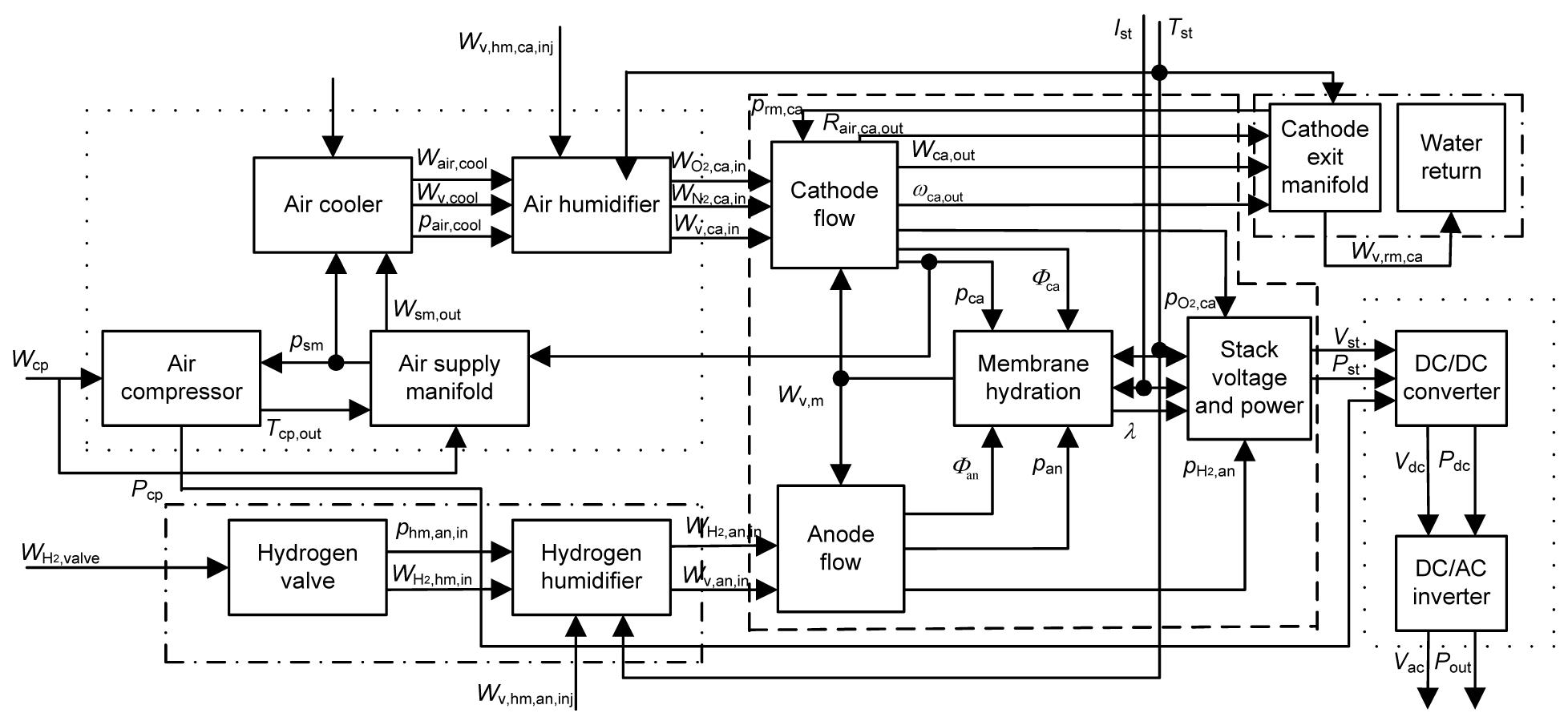
2.2. Generation system model
In the Simulink/Matlab environment, a 60 kW PEMFC generation system has been modeled in order to design the system parameters and investigate the static and dynamic characteristics for control purposes. As shown in Fig. 2, some interacting sub-models of the PEMFC stack, cathode air supply, anode fuel supply, cathode exhaust exit, and power conditioning are connected in modules to build an overall 60 kW PEMFC generation system as described in (Zhang et al., 2011). Construction of the system model is mainly based on the reactants’ dynamic flow, electrochemical reaction, and power transformation, i.e., the system operation parameters and power output variation. The model is based on the ideal gas equation, matter energy conservation, and physical chemistry laws. It has been validated that the model, which is mathematically simple for system parameters and control designs, can represent the static and dynamic characteristics of a 60 kW PEMFC generation system.
The heat management of the system has also been described by Zhang et al. (2006). With its relatively slow responses, the stack temperature can be viewed as a separate control system in heat management and assumed to be constant at 75 °C.
3. System control strategy
The 60 kW PEMFC generation system has to be kept at a constant voltage and steady operation in residential applications, while the current is drawn based on the power demand load. As described in the system model, except for temperature, the system current (instantaneously drawn by the load representing the user demand), the air flow rate at the compressor exit, the exhaust flow rate through the cathode exhaust valve, the water injection for air humidification, the hydrogen flow rate through the second pressure relief valve, the water injection for hydrogen humidification, the duty ratio of the converter and the modulation factor of the inverter are all input variables, that is to say, adjustable variables in the system operation. The output power, output voltage, oxygen excess ratio, anode and cathode gas pressures, anode and cathode relative humidities are all important system performance factors. A 60 kW PEMFC generation system is a nonlinear multiple-input multiple-output (MIMO) control system.
3.1. Anode side control strategy
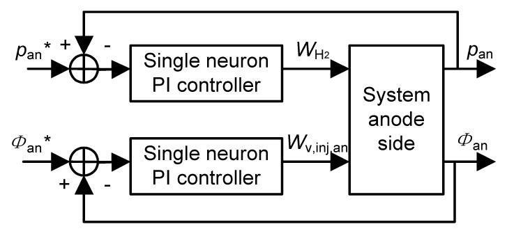
The stack anode has to be maintained at a suitable pressure and humidity to avoid detrimental degradation of performance, and thus a reduction in efficiency. As shown in Zhang et al. (2011), anode humidity Φan influences anode pressure pan through the vapor partial pressure pv,an. pv,an is related to the water transport across the membrane, which is influenced by pan and Φan. The anode side is thus a nonlinear dynamic and coupling system. Variable inputs are the hydrogen flow rate through the second valve and the water injected into the hydrogen by the pump Wv,inj,an. The drawn current Ist, cathode pressure pca, and cathode humidity Φca are all regarded as disturbances for anode side control. The coupling is considered as a disturbance in the control. Thus, this two-variable coupling system is regarded as two single-loop control systems. Fig. 3 presents the control strategy on the anode side. The traditional proportional-integral (PI) control method is selected due to its simple structure, easy implementation, and robustness. Considering so many disturbances, close dynamic characteristics, and other problems in real applications, an intelligent single neuron PI controller is designed for greater adaptive ability.
Fig.3 Intelligent PI decoupling control strategy for anode side
The anode humidity is kept stable by adjusting Wv,inj,an. The control error is defined as e(k)=Φan−Φan*. Based on the optimal control theory, a quadratic index J=e2(k)/2 is introduced in the single neuron PI control design. The weight is adjusted along the negative gradient direction of J versus wi in the learning process. The learning algorithm is standardized as
where k is the current time, ηi (i=1, 2) are the learning rates of proportional and integral terms, and K is the gain of neurons. Inputs xi(k) (i=1, 2) are defined as
.
Initial states of weights wi are set randomly. Setting K and ηi suitable, the error e(k) can be well controlled in the self-adaptive process.
The anode pressure is kept suitable by adjusting . The control design is the same as that for anode humidity. The control error is defined as e(k)=pan−pan*.
3.2. Cathode side control strategy
The stack cathode has also to be maintained at suitable pressure and humidity for good operating conditions. The cathode side is also a close nonlinear dynamic and coupling system. The drawn current, anode pressure, and anode humidity are regarded as disturbances. As described in the system model, input variables are air flow rate through the compressor Wcp, exhaust flow rate through the exhaust valve Wrm,ca,valve, and water injected into the air by the pump Wv,inj,ca. The oxygen excess ratio , defined as the ratio of oxygen supplied to oxygen used in the cathode, relates to the air flow rate through the compressor Wcp and the current drawn from the system Ist:
,
where F is the Faraday number, n is the cell number in the stack, and is the oxygen molar mass. For a 60 kW PEMFC generation system, the highest net power is achieved at an oxygen excess ratio around two. For simplification a fixed is assumed. A feed-forward proportional controller is used to regulate by adjusting Wcp as shown in Fig. 4. As on the anode side, a two-variable single neuron PI decoupling controller is designed to keep both the cathode pressure pca and the humidity Φca suitable.
Fig.4 Intelligent decoupling control strategy for cathode side
3.3. Power control strategy
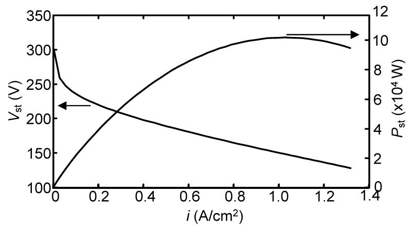
The operating parameters of a 60 kW PEMFC including the oxygen excess ratio, temperature, pressures, and humidity in anode and cathode are all controlled constant to maintain good working conditions. The relationships among the voltage, the power, and the current density of the stack can be described by polarization curves. Fig. 5 shows the experimentally measured polarization curve of a 60 kW PEMFC stack under the desired working conditions. The stack power depends on the current density i, which is called the operating point. The load power demand Pdemand is time-varying in residential applications. It is necessary to adjust the system operating point to track the immediate power demand. The conversion efficiency η of the power conditioning and the parasitic power consumption Ppara are considered. The desired output power of a 60 kW PEMFC stack should be:
.
Fig.5 60 kW PEMFC polarization curve
As shown in Fig. 5, it is necessary for the generation system to find the optimal operating point i*(k) in the polarization curve to make the stack provide the desired output power Pst(k)=Pst*(k). Due to the monotonic relation between the stack power and the current density before the power peak, the optimal seeking process is easy. Most of the one-dimension search methods such as the bisection, golden section, quadratic interpolation, gradient descent, and hill climbing, are applicable to the search for the optimal operating point of a 60 kW PEMFC stack.
3.4. Voltage control strategy
The 60 kW PEMFC stack has an unregulated low DC voltage in residential applications, which fluctuates with the operation points. The power conditioning unit is used to convert the raw voltage into useable voltage for loads. In residential buildings in China, the voltage is generally 220 V, 50 Hz and AC. The root-mean-squared (RMS) voltage of the inverter is maintained at 220 V. The output voltage of the converter is maintained at 380 V, and the control strategy for the power conditioning unit is shown in Fig. 6. A pulse-width modulation (PWM) generator adjusts the duty ratio D of the converter to control the output voltage Vdc based on the difference between Vdc and Vdc*. The same negative feedback design is used to control the output voltage Vac of the inverter by adjusting the modulation factor m. For high performance, the control design of the power conditioning unit should have a simple structure, rapid response, and also adaptability and anti-interference. The PI control method, which is the most popular control method in industrial applications, is still used. For close dynamic characteristics of the generation system, an intelligent adaptive single neuron is combined with the PI control method.
Fig.6 Control strategy for the power conditioning unit
4. Generation system simulation test
The purpose of the simulation tests is to check the control strategy presented for the 60 kW PEMFC generation system. The steady operation of a 60 kW PEMFC generation system is investigated, excluding start-up and shut-down processes. Thus, the initial states of the model parameters are all set near to their desired values. The simulation model tuned runs well and represents the dynamic characteristics of the generation system. Some controllers designed above are established in M-function modules and are then jointed into the system on the anode side, cathode side, optimal operation point seeking and power conditioning model units. In the control tests, changing signals are instantaneously drawn from the system load representing dynamic user demand. The 60 kW PEMFC generation system adaptively adjusts the hydrogen flow rate and the water injection to maintain anode pressure and humidity. It also adaptively adjusts the exhaust flow rate and the water injection to maintain the desired cathode pressure and humidity. It calculates the air flow rate through the compressor directly to maintain the oxygen excess ratio. It controls its output voltage suitable for the load use by two negative feedback controllers. Fig. 7 shows system responses to step changes in the load power demand. It is important to understand that these abrupt changes of the load power demand are for testing the dynamic response of the system control strategy, and do not necessarily represent changes in real residential loads.
Fig.7 Responses of a 60 kW generation system to the step changes of load power demand: (a) step changes of load power demand and responses of system output power; (b) responses of cathode pressure; (c) responses of anode pressure; (d) responses of anode and cathode humidity; (e) responses of converter output voltage; (f) responses of inverter output voltage
Comparison of the load power demand and the system power response indicates that 60 kW PEMFC generation system demonstrates rapid responses to load step changes and exhibits a good load-following capability. It is maintained at desired operational conditions and always supplies a suitable voltage. The control strategy of the overall generation system presented in this work is therefore effective in keeping its steady operational conditions automatically. The parameter setting for the control design impacts on the generation system performance. The gain of neurons K is set by testing and experiment first. The larger K is, the faster the controller responds. But the system may have a large overshoot and even become unstable. When the delay of the controlled object increases, K must be reduced to ensure the system is stable. However, the value of K cannot be set too small as that may impair its response time. After K is determined, the learning rates η1 and η2 correspond to the proportional and integral terms in PI control respectively. Thus, η1 and η2 are adjusted according to the law of parameters in PI control. In the simulation test as shown in Fig. 7, parameters of the anode humidity controller are: K=3×10⁻⁴, η1=0.8, and η2=100, and the parameters of the anode pressure controller are: K=1×10⁻⁶, η1=0.1, and η2=100. In the cathode side, parameters of the humidity controller are: K=30, η1=0.1, and η2=100, and the parameters of the pressure controller are: K=8×10⁻⁶, η1=0.01, and η2=1000. The golden-section algorithm is used for the power controller to search optimal operating points in the generation system in the simulation test. Suppose the current time is k. The searching process of the optimal operating point i*(k) starts from i(k−1) and uses the step size h=1. The objective function is f=|Pst−Pst*|. When f is less than 10, the searching process ends. In the power conditioning unit, the parameters of the converter controller are: K=6×10⁻⁵, η1=100, and η2=100, and the parameters of the inverter controller are: K=9×10⁻⁶, η1=0.01, and η2=100.
5. Conclusions
The heat management and control-oriented system model of a 60 kW PEMFC generation system for residential applications has been described in earlier research (Zhang et al., 2011). The system is currently at the stage of control design and development. The 60 kW PEMFC generation system is a nonlinear multi-variable and dynamic coupling control system. In this work, the overall control strategy of the system was proposed and tested. Controllers in anode and cathode sides were designed to maintain both pressures and humidity at their desired values. The power controller was designed to follow load power demand. The voltage controllers were designed for a suitable output voltage for load uses. The simulation tests had been conducted based on the step changes of the load power demand. The results showed that the adaptive control strategy proposed was robust with respect to system variation and power demand. This control study was very important for 60 kW PEMFC generation system research and will give guidance for the further development and application of the system.
[1] Caux, S., Lachaize, J., Fadel, M., Shott, P., Nicod, L., 2005. Modeling and control of a fuel cell system and storage elements in transport applications. Journal of Process Control, 15(4):481-491.
[2] Chen, P.C., 2011. Output-feedback voltage tracking control for input constrained PEM fuel cell systems. International Journal of Hydrogen Energy, 36(22):14608-14621.
[3] Chrenko, D., Pra, M.C., Hissel, D., Geweke, M., 2008. Macroscopic modeling of a PEFC system based on equivalent circuits of fuel and oxidant supply. Journal of Fuel Cell Science and Technology, 5(1):011015
[4] Chrenko, D., Pra, M.C., Hissel, D., Bouscayrol, A., 2009. Inversion-based control of a proton exchange membrane fuel cell system using energetic macroscopic representation. Journal of Fuel Cell Science and Technology, 6(2):024501
[5] Hatti, M., Tioursi, M., 2009. Dynamic neural network controller model of PEM fuel cell system. International Journal of Hydrogen Energy, 34(11):5015-5021.
[6] Kunusch, C., Puleston, P.F., Mayosky, M.A., Fridman, L., 2013. Experimental results applying second order sliding mode control to a PEM fuel cell based system. Control Engineering Practice, 21(5):719-726.
[7] Panos, C., Kouramas, K.I., Georgiadis, M.C., Pistikopoulos, E.N., 2012. Modelling and explicit model predictive control for PEM fuel cell systems. Chemical Engineering Science, 67(1):15-25.
[8] Park, G., Gajic, Z., 2012. Sliding mode control of a linearized polymer electrolyte membrane fuel cell model. Journal of Power Sources, 212:226-232.
[9] Pukrushpan, J.T., Stefanopoulou, A.G., Huei, P., 2002. Modeling and Control for PEM Fuel Cell Stack System. , Proceedings of the American Control Conference, Anchorage, Alaska, USA, 3117-3122. :3117-3122.
[10] Rodatz, S., Paganelli, G., Guzzella, L., 2003. Optimizing Air Supply Control of a PEM Fuel Cell System. , Proceedings of the American Control Conference, Denver, USA, 2043-2048. :2043-2048.
[11] Tong, S.W., Qian, D.W., 2013. Control of a fuel cell based on the SIRMs fuzzy inference model. International Journal of Hydrogen Energy, 38(10):4124-4131.
[12] Yang, Y.P., Liu, Z.W., Wang, F.C., 2008. An application of indirect model reference adaptive control to a low-power proton exchange membrane fuel cell. Journal of Power Sources, 179(2):618-630.
[13] Zhang, Y.Y., Yu, Q.C., Cao, G.Y., Zhu, X.J., 2006. Research on a simulated 60 kW PEMFC cogeneration system for domestic application. Journal of Zhejiang Universit-SCIENCE A, 7(3):450-457.
[14] Zhang, Y.Y., Sun, J.C., Zhang, Y., Li, X., Cao, G.Y., 2011. Dynamic modeling and simulation test of a 60 kW PEMFC generation system. Journal of Zhejiang University-SCIENCE A (Applied Physics & Engineering), 12(6):475-482.
Open peer comments: Debate/Discuss/Question/Opinion


Open peer comments: Debate/Discuss/Question/Opinion
<1>