1. Introduction
Future space science instruments, including
γ-ray and mid-long wave infrared sensors, require cryogenic refrigeration of about 10–500 mW down to 4–6 K to improve their dynamic range, extend wavelength coverage, or provide precooling for the use of advanced detectors such as space microcalorimeters and thermal radiometers (Ross and Johnson,
2006). Pulse tube cryocoolers (PTCs) operate with oscillating pressure and mass flow with no moving parts at the cold end. Compared with a G-M type pulse tube cryocooler (GMPTC) that operates at about 1–2 Hz (Gao and Matsubara,
1994; Wang et al.,
1997; Chen et al.,
1997), a Stirling type pulse tube cryocooler (SPTC), operating at 30–60 Hz, has a compact structure and light weight, making it very appealing for space and military applications mentioned above (Kotsubo et al.,
1998; Radebaugh,
1999; Marquardt and Radebaugh,
2000; Tward et al.,
2001; Gan et al.,
2008; Yan et al.,
2009).
Compared with the relatively matured 80 K SPTCs, the efficiency of 4 K SPTCs is still rather low (about 0.5%–1% Carnot efficiency) (Olson et al.,
2006; Nast et al.,
2007;
2008; Bradley et al.,
2008; Radebaugh et al.,
2008; Qiu et al.,
2011) due to regenerator losses with both the 4 K low temperature region (van Sciver,
1986) and high operating frequencies (Tanaeva et al.,
2006). At temperatures below about 15 K, the specific heat capacity of regenerator materials significantly decreases with the cube of the temperature, while the specific heat capacity of helium-4 (He-4) increases remarkably, which leads to large regenerator heat transfer loss. As a result, regenerator materials with large heat capacity, such as magnetic ceramic materials, should be used to improve heat transfer. In addition, the high operating frequency yields smaller thermal penetration depth of helium, which makes the heat transfer between the matrix and helium worse. SPTC usually adopts a three- or even a four-stage regenerator structure to precool the final stage regenerator to reach the 4 K temperature region (Olson et al.,
2006; Nast et al.,
2007;
2008; Qiu et al.,
2011). The number of the regenerator stages is influenced by both the performance of the final stage regenerator and the precooling capacity of the previous stage regenerators working at warmer temperature regions (typically above 80 K). There exists complicated interference between different stages of the regenerators. To get a better understanding of 4 K regenerator characteristics at high frequencies and determine the relationship between the different stages of regenerators, a single-stage SPTC precooled by a two-stage GMPTC was developed and manufactured (Li et al.,
2008; Qiu et al.,
2008). The SPTC and the GMPTC are thermally coupled by two thermal bridges. By using this method, we can focus on the final 4 K stage regenerator performance. The first and second precooling temperatures provided by the two-stage GMPTC can be varied in a wide range to see their effect on the 4 K stage regenerator. Furthermore, the first and second precooling powers can be obtained by calculating the thermal bridges according to the temperature differences. These are important parameters to evaluate efficiency of the whole system, which offers useful guidance for the design of a three-stage 4 K SPTC. Previously we verified the possibility of reaching the 4 K temperature region at high frequency (about 30 Hz) with He-4 as the working fluid (Gan et al.,
2009). In this paper, a multi-layer regenerator matrix including Gd
2O
2S (GOS) and HoCu
2 was used instead of a single-layer HoCu
2 around 4 K to investigate the effect of regenerator materials on the performance of a 4 K regenerator at high frequencies. A comparison between two types of regenerator materials of GOS and HoCu
2 was made, including the influence of average pressure and frequency on 4 K regenerator losses at high frequencies.
2. Calculated results of regenerator materials
2.1. Regenerator materials at 4 K
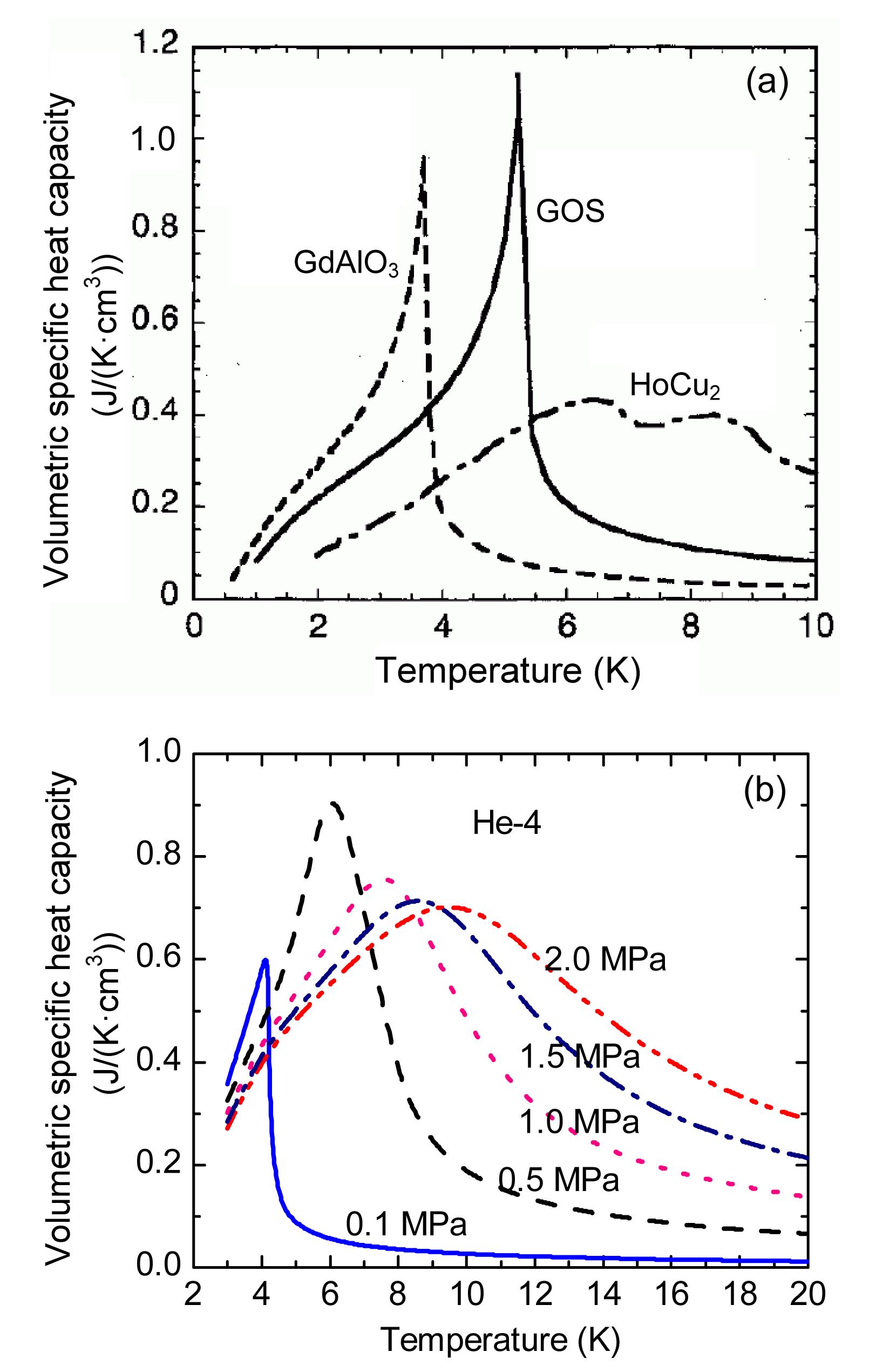
For effective heat transfer, the volumetric specific heat capacity of the regenerator matrix should be much larger than that of the working fluid helium. Fig.
1 shows the volumetric specific heat capacity of the regenerator matrix typically used below 20 K (Numazawa et al.,
2004) as well as that of helium at different average pressures. The specific heat capacity of the regenerator materials is rather small around 4 K while the specific heat capacity of helium increases as the temperature decreases. The maximum specific heat capacity of the ceramic magnetic regenerator material GOS has a peak value of about 1.2 J/(K·cm
3) at 5.5 K with a sharp shape, while HoCu
2 has a relatively small volumetric specific heat capacity of about 0.25–0.4 J/(K·cm
3) with a smooth shape from 4 K to 20 K. As a result, a multi-layer regenerator matrix including GOS might improve the regenerator performance around 4 K.
Fig.1
Volumetric specific heat capacity of regenerator materials (a) and He-4 (b) below 20 K
2.2. Calculated performance of 4 K regenerator materials
SPTC usually uses three or even four stages of regenerators to decrease regenerator losses to reach 4 K. The performance of the final stage is vital for the overall efficiency of a 4 K SPTC and is calculated based on a well-known regenerator software REGEN 3.3 (Gary and O’Gallagher,
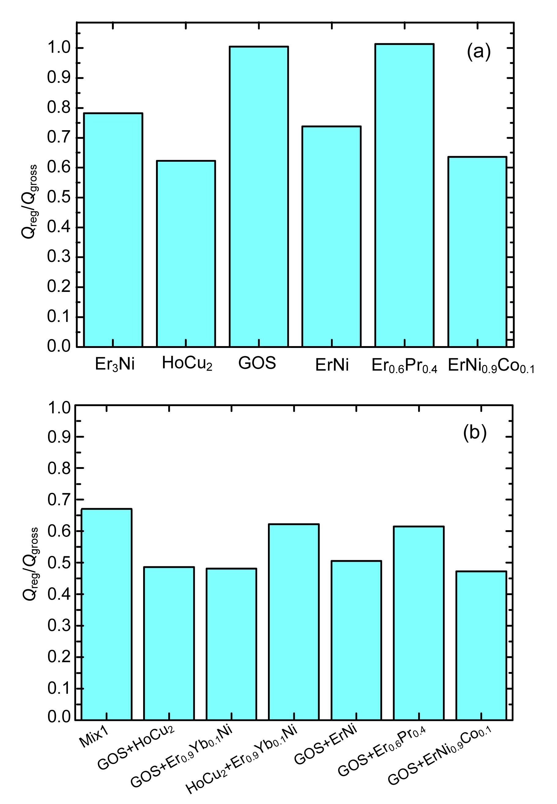
2006). Figs.
2a and 2b compare the relative regenerator losses working at 4–10 K with single-layer and multi-layer regenerator materials. The pressure ratio (
r
P=
P
max/
P
min) at the cold end is fixed at 1.2 and the average pressure (
P
0) is 1.0 MPa. The cold end temperature (
T
c) and the hot end temperature (
T
h) of the final stage regenerator are 4 K and 10 K, respectively. A ratio of regenerator heat transfer loss to the gross cooling power (
Q
reg/
Q
gross) is used to evaluate the efficiency of the regenerator. For single-layer regenerator materials, HoCu
2 yields the smallest regenerator loss of about 63%. By using multi-layer regenerator materials, the performance of 4 K regenerator is improved and the regenerator loss is reduced to about 48% with combination of GOS and HoCu
2.
Fig.2
Effect of single-layer (a) and multi-layer (b) regenerator materials on 4 K regenerator losses
r
P=1.2; P
0=1.0 MPa; T
c=4 K; T
h=10 K; cryocooler working frequency is f=30 Hz
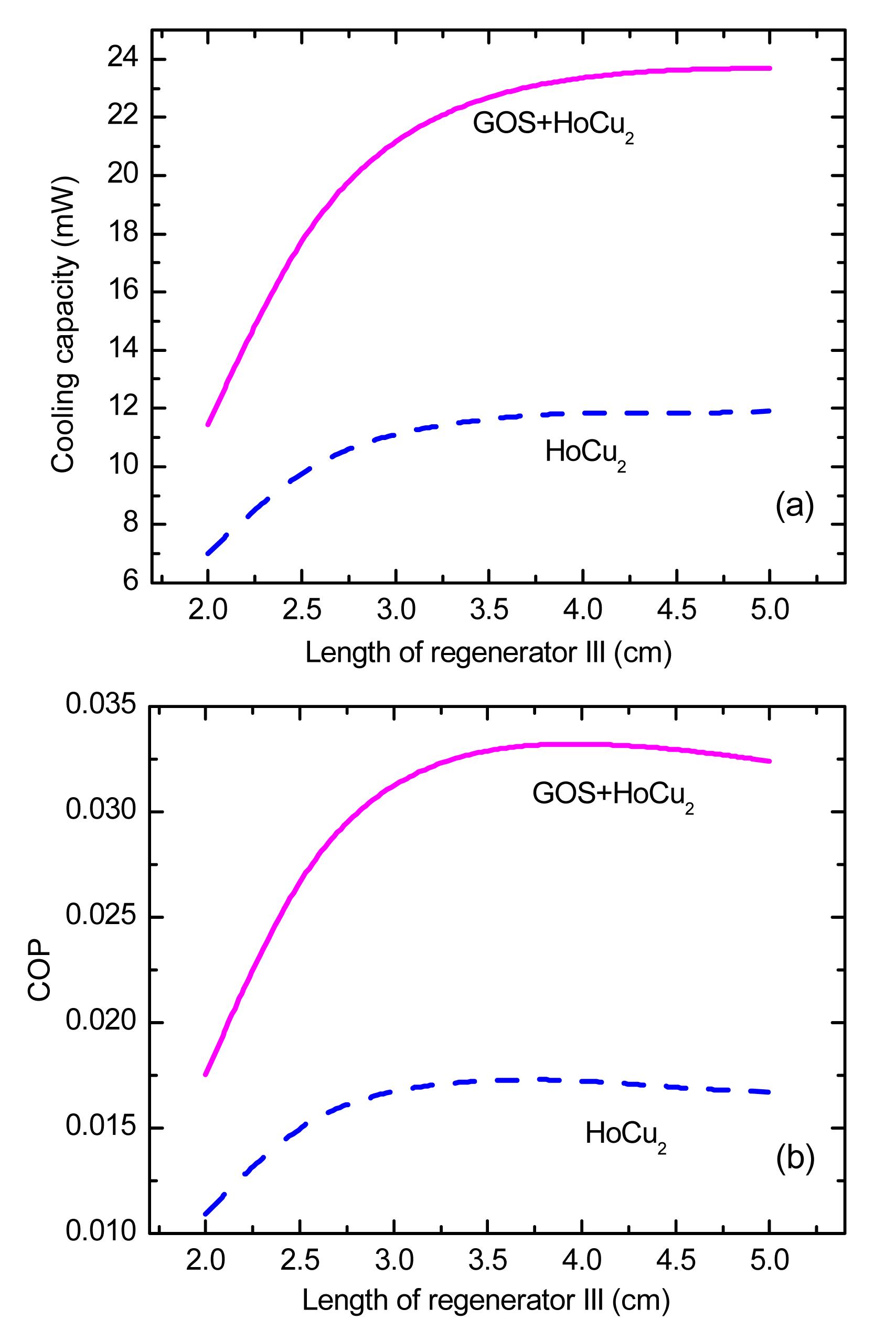
A more detailed comparison between the two types of regenerator materials mentioned above is given in Fig.
3. We can see that both the cooling capacity at the cold end and the coefficient of performance (COP) of the SPTC are significantly improved by using GOS. Moreover, the cooling capacity of the case with GOS is increased to about twice that of the case without GOS. The optimum regenerator length for GOS is larger than that with only HoCu
2.
Fig.3
Comparison of cooling capacity (a) and COP (b) between regenerator materials of HoCu2 and GOS+HoCu2
f=30 Hz; P
0=1.0 MPa; r
P=1.2
3. Experimental setup
The schematic of the 4 K SPTC precooled by a two-stage GMPTC is shown in Fig.
4. The GMPTC is driven by a helium compressor with an input power of 7.5 kW and the SPTC is driven by a linear compressor with a maximum input power of 280 W. The operating frequency of the linear compressor can be varied from 25 Hz to 70 Hz. The regenerator of the SPTC consists of three sections (I, II, and III) according to the designed temperature ranges as shown in Fig.
4. The 4 K SPTC works in the cold inertance tube mode (Olson,
2005). Cold inertance tube and reservoir were designed as the phase shifter of the SPTC for better phase relationship between the pressure and mass flow, which are placed at the second stage thermal bridge at about 10 K (Gan et al.,
2009). Two thermal bridges located at the first stage cold end and the second stage cold end of the GMPTC, respectively, are adopted to provide the required precooling for the SPTC at the joint positions of the regenerator sections. The arrangement of thermometers is also shown in Fig.
4. The temperature at the cold end of the SPTC (T4) is measured by a calibrated Cernox thermometer (accuracy of 0.014 K below 10 K), and five calibrated Rh-Fe resistance thermometers (accuracy of 0.1 K) are used to measure temperatures at T1–T3 and T5–T6. Two electrical heaters are mounted at the first stage and the second stage cold ends of the GMPTC, respectively, to adjust the precooling temperatures. The precooling power provided by the two-stage GMPTC was measured by calibrating the thermal bridges according to the temperature differences at the two ends of the thermal bridges previously. Fig.
5 gives the calibration results of the second thermal bridge. The measured thermal resistances of the second and first thermal bridges are 0.601 K/W and 3.498 K/W at about 10 K and 50 K, respectively. The static and dynamic pressures at the inlet of the regenerator of the SPTC (P1) are also measured. He-4 is used as the working fluid. The main parameters of the 4 K SPTC are listed in Table
1.
Fig.4
Schematic of a single-stage SPTC with precooling
P1: static and dynamic pressure at the warm end of the SPTC; T1: first precooling temperature; T2: second precooling temperature; T3: temperature of cold inertance tube; T4: refrigeration temperature at cold end of the SPTC; T5: first cold end temperature of the GMPTC; T6: second cold end temperature of the GMPTC
Fig.5
Calibration of the second thermal bridge
Table 1
Main parameters used in the calculation for the 4 K regenerator
| Regenerator |
T
c (K) |
T
h (K) |
D (mm) |
L (mm) |
Regenerator matrix |
Porosity |
| I |
T1 |
300 |
15.4 |
30 |
#400 stainless steel screen |
0.686 |
| II |
10 |
T1 |
15.4 |
30 |
#400 stainless steel screen, lead spheres |
0.686 0.380 |
| III |
4 |
10 |
12.4 |
30 |
HoCu2/(GOS+HoCu2) |
0.380 |
| Pulse tube |
4 |
10 |
4.8 |
30 |
| Inertance tube |
|
10 |
1.0 |
360 |
D: regenerator diameter; L: regenerator length; f=30 Hz; P
0=1.0 MPa; r
P=1.2; volume of the reservoir is 250 cm3
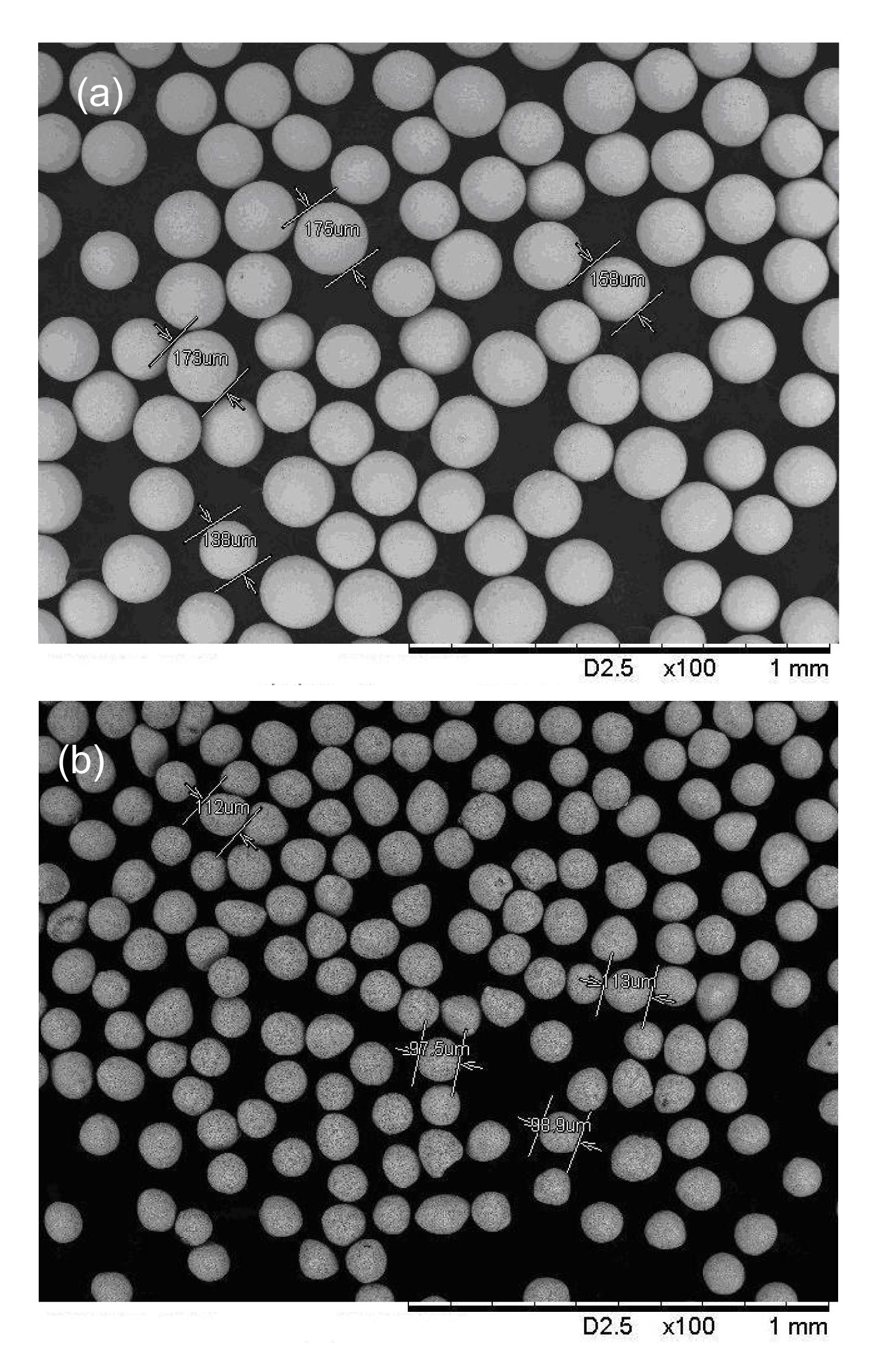
Fig.
6 shows the photos of the regenerator material particles of HoCu
2 and GOS under a microscope used in the experiment. The diameter of the HoCu
2 particles lies in the range of about 0.14–0.18 mm, while the diameter of the GOS particles is about 0.10–0.11 mm. Fig.
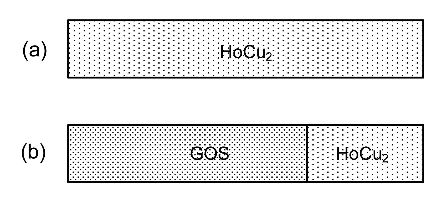
7 shows the composition of the single-layer and multi-layer regenerator matrices compared in the calculation and experiment. For simplicity, the two cases are referred to as CASE 1 and CASE 2. The proportion of GOS and HoCu
2 in CASE 2 is arranged according to the calculated temperature distribution along regenerator III operating at 4–10 K (Fig.
8). The GOS particles are filled in the regenerator where the temperature is below 5.5 K with a filling length of about 20 cm in regenerator III as shown in Fig.
8.
Fig.6
Photos of HoCu2 particles (a) and GOS particles (b) under a microscope used in the experiment
Fig.7
Regenerator materials of regenerator III for CASE 1 (a) and CASE 2 (b)
Fig.8
Calculated temperature distribution along regenerator III
4. Experimental results and discussion
4.1. Influence of regenerator materials on the performance of the linear compressor
The performance of the linear compressor driving the 4 K SPTC was affected by the regenerator materials due to the change of the cryocooler impedance. The input power (
W
input) of the linear compressor is fixed at 50 W. Figs.
9a and 9b give the influence of the operating frequency on the output current of the linear compressor and the pressure ratio (
r
1) at the inlet of the SPTC. The optimum operating frequency for the two cases is 35 Hz, where the current is the smallest, leading to a minimum Joule heat loss. Furthermore, the pressure ratio for CASE 2 with GOS is larger than that of CASE 1 because of the increased regenerator impedance associated with the relatively small sphere diameter of GOS particles. In addition, the geometry of the GOS particles is also more evenly distributed.
4.2. Influence of the regenerator materials on the performance of 4 K SPTC
The influences of the frequency on the refrigeration temperature of the SPTC with different average pressures for CASE 1 and CASE 2 are shown in Fig.
10. The precooling temperature (T2) was kept constant at 7.9 K. As can be seen from Fig.
9, the performance of the 4 K SPTC is improved as the average pressure decreases for both CASE 1 and CASE 2 due to the reduction of real gas losses at low pressures (Yoshimura et al.,
1999; Gan et al.,
2009). As the average pressure goes down from 1.0 MPa to 0.52 MPa, the optimum frequency is decreased from about 38 Hz to 33 Hz for the two cases.
Fig.9
Effect of regenerator materials on performance of the output current of the linear compressor (a) and the pressure ratio (b) at the inlet of the SPTC
Fig.10
Effect of the operating frequency on the refrigeration temperature for CASE 1 (a) and CASE 2 (b)
Note that the refrigeration performance of the 4 K SPTC is more sensitive to frequency at lower average pressures. For CASE 1 the refrigeration temperature even exceeds the precooling temperature as the frequency increases to 40 Hz at 0.84 MPa and 0.52 MPa. The main reason may be that as the average pressure decreases, the specific heat capacity of He-4 increases significantly and the temperature with the maximum specific heat capacity decreases as shown in Fig.
1. The maximum specific heat capacity of He-4 reaches 0.9 J/(K·cm
3) at 6 K when the average pressure is 0.5 MPa. The specific heat capacity ratio of the regenerator matrix to helium is seriously degraded leading to a severe regenerator heat transfer loss. As a result, a lower operating frequency is needed to decrease the regenerator losses.
The performance of the 4 K SPTC is not obviously improved with the use of GOS, especially at higher average pressures. The temperature along the regenerator is higher than that expected in the calculation. The reason may be that the pressure drop along the regenerator is increased with the filling of the GOS particles with a smaller diameter. Therefore, the pressure ratio at the cold end for the case with GOS is smaller than 1.2 assumed in the calculation. The specific heat capacity of HoCu
2 is larger than that of GOS at temperature regions above 5.5 K.
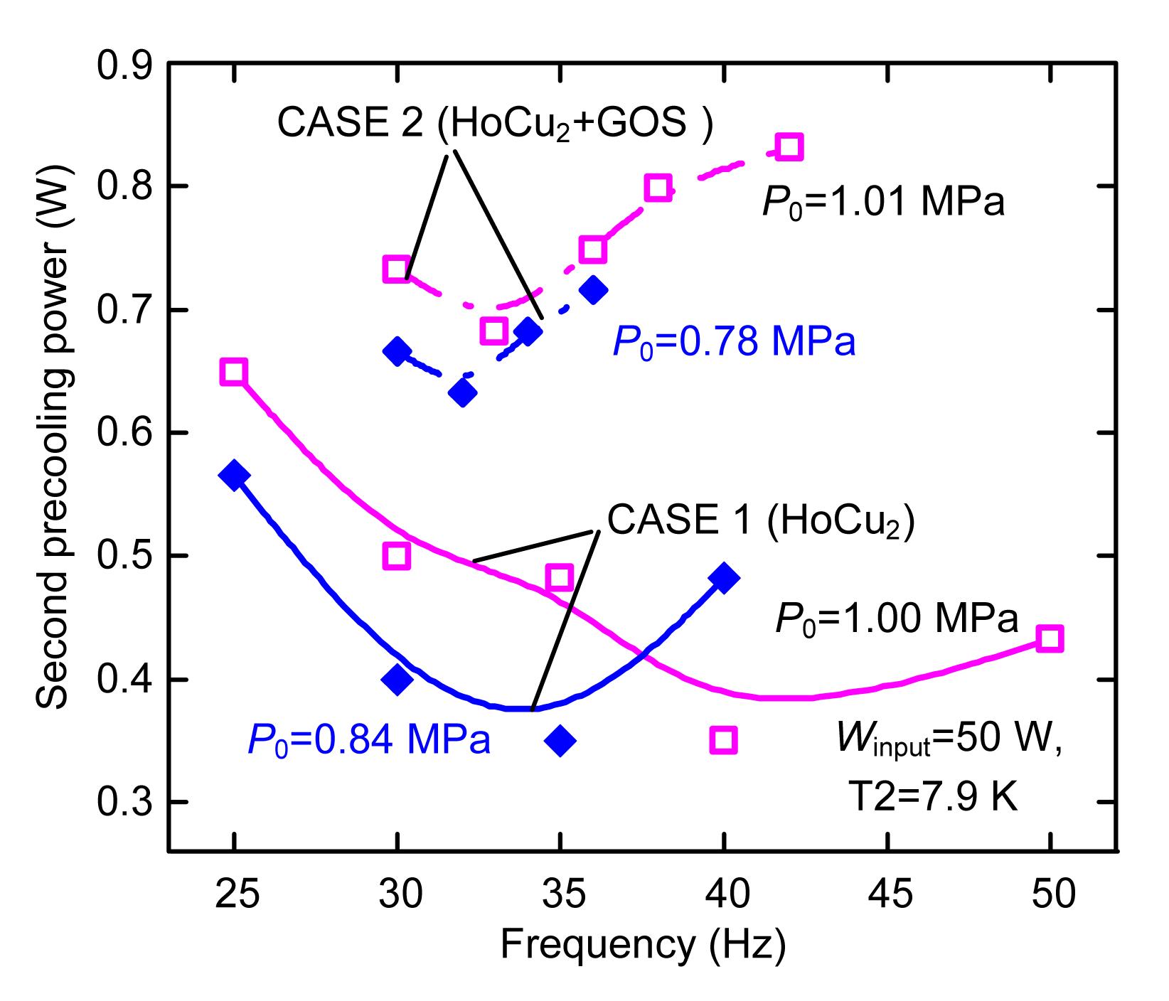
The two-stage GMPTC plays the role of a two-stage SPTC when we design a 4 K three-stage SPTC. Thus, the first and second precooling power provided by the GMPTC is useful for evaluating the performance of regenerators working at warmer temperature stages. Fig.
11 provides the comparison of the effect of the operating frequency on the second precooling power (enthalpy difference between Regenerator II and Regenerator III) for CASE 1 and CASE 2.
Fig.11
Effect of the operating frequency on the second precooling power
For both of the two cases, the lower average pressure yields the smaller second precooling power. The optimum frequency also decreases with the average pressure, which is caused by the same reason mentioned above. The second precooling power for CASE 2 is larger than that of CASE 1 due to increased regenerator imperfect heat transfer loss of Regenerator III. The minimum second precooling power for CASE 1 and CASE 2 are 0.68 W and 0.35 W at 7.9 K, respectively, with an average pressure of 1.0 MPa.
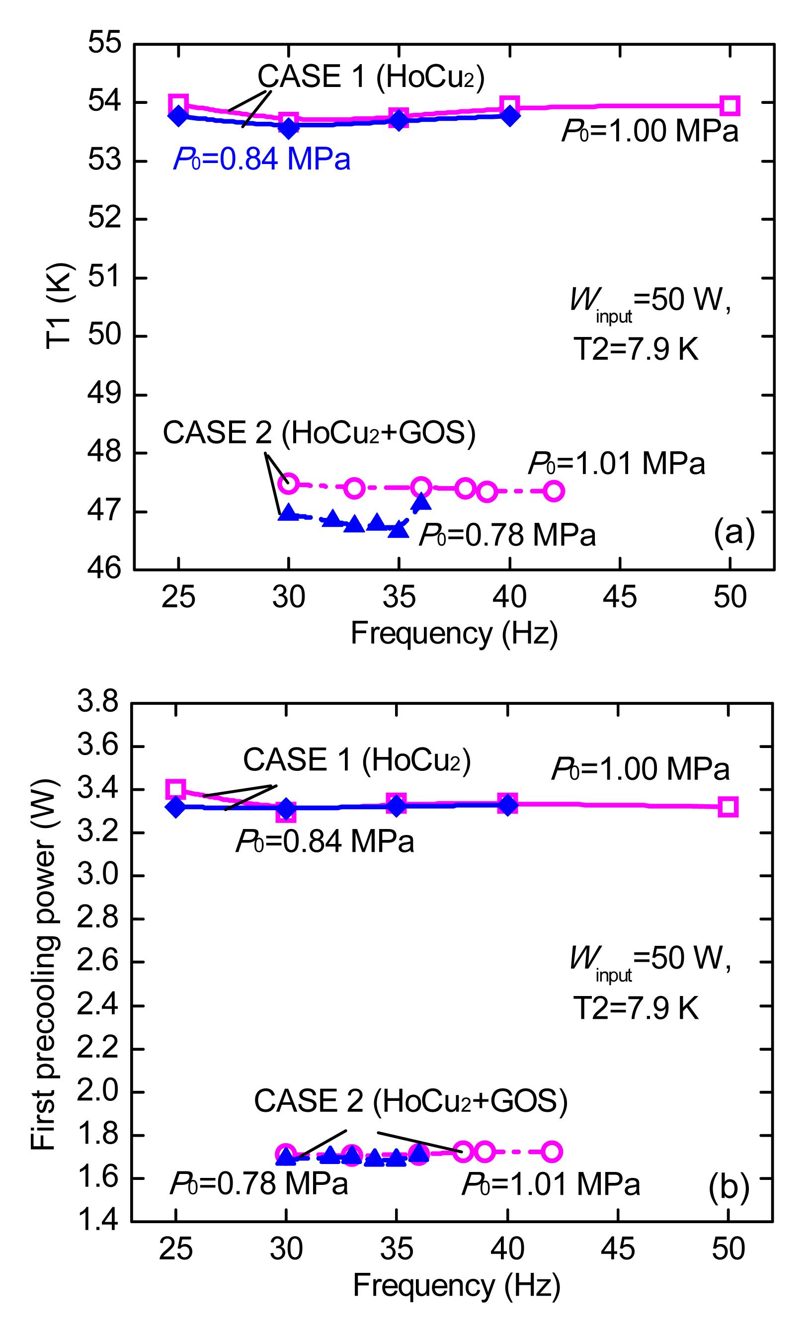
Fig.
12 gives the effect of the operating frequency on the first precooling temperature and the first precooling power under different average pressures for CASE 1 and CASE 2. In the experiment, no additional heat was added to the first thermal bridge. As a result, the first precooling temperature was only influenced by the performance of Regenerator II and Regenerator I. Note that both T1 and the first precooling power are almost independent of the frequency and average pressures.
Fig.12
Effect of the operating frequency on the first precooling temperature (a) and the first precooling power (b)
It is also interesting that with the use of GOS, both the first precooling temperature and the first precooling power are remarkably reduced compared to CASE 1. For example, with an average pressure of 1.0 MPa the first precooling temperature for CASE 2 is about 6.3 K lower than that of CASE 1, and the precooling power is only half that of CASE 1. An explanation may be that the GOS sphere particles have a smaller diameter which leads to a smaller porosity in the Regenerator III. There will be less helium gas leaving in the void volume of the regenerator (equal to
PV
rg/(
ZRT
m), where
V
rg is the void volume of regenerator,
T
m is the mean temperature of regenerator,
Z is the compressibility factor accounting for real gas effects, and
R is the gas constant for helium gas). The porosity of Regenerator III has a larger influence with a lower mean temperature. As a result, it is more difficult to achieve an ideal phase shift provided by the cold inertance tube at the warm end of the pulse tube with the mass flow and the pressure being in phase in the middle of the regenerator (Radebaugh et al.,
2006). With this situation, the performances of Regenerator II and Regenerator I will be severely degraded for CASE 1.
5. Conclusions
A single-stage SPTC precooled by a two-stage GMPTC was developed to further understand the characteristics of 4 K regenerators at high frequency and the interference between different stages of the regenerator. A multi-layer regenerator matrix including GOS and HoCu
2 was used instead of a single-layer HoCu
2 around 4 K to reduce regenerator losses. A no-load refrigeration temperature of 5.4 K was achieved with the precooling power of 0.416 W @7.9 K and 3.348 W@54.1 K at 0.52 MPa and 35 Hz with HoCu
2 as the regenerator material. Lower average pressure yields a lower refrigeration temperature and a second precooling power. However, the performance of the final stage regenerator is strongly sensitive to operating frequencies especially at low average pressures, due to the fact that the volumetric specific heat capacity of He-4 near 4 K significantly increases as the average pressure decreases. In contrast, the behavior of regenerators working at warmer stages is almost independent of frequencies and average pressures. Regenerator material porosity in the final stage has a significant effect on the first precooling power in that it severely influences the phase shift between the mass flow and pressure in the regenerator. The precooling power of the first stage is reduced remarkably in the case of the GOS filling.
* Project supported by the National Natural Science Foundation of China (No. 51106071), and the Priority Academic Program Development of Jiangsu Higher Education Institutions, ChinaReferences
[1] Bradley, P.E., Radebaugh, R., Garaway, I., 2008. Progress in the development and performance of a high frequency 4 K Stirling-type pulse tube cryocooler.
, 16th International Cryocooler Conference, GA, USA, 27-34. :27-34.
[2] Chen, G.B., Qiu, L.M., Zheng, J., 1997. Experimental study on a double-orifice two-stage pulse tube refrigerator.
Cryogenics, 37(5):271-273.

[3] Gan, Z.H., Liu, G.J., Wu, Y.Z., 2008. Study on a 5.0 W/80 K single stage Stirling type pulse tube cryocooler.
Journal of Zhejiang University-SCIENCE A, 9(9):1277-1282.
[4] Gan, Z.H., Li, Z.P., Qiu, L.M., 2009. Design and preliminary experimental investigation of a 4 K Stirling type pulse tube cryocooler with precooling.
Journal of Zhejiang University-SCIENCE A, 10(9):1277-1284.
[5] Gao, J.L., Matsubara, Y., 1994. Experimental investigation of 4 K pulse tube refrigerator.
Cryogenics, 34(1):25-30.
[6] Gary, J., OGallagher, A., 2006. REGEN 3.3: User Manual. National Institute of Standards and Technology,USA :
[7] Kotsubo, V., Olson, J.R., Nast, T.C., 1998. Development of a 2 W at 60 K pulse tube cryocooler for spaceborne operation.
, 10th International Cryocooler Conference, CA, USA, 157-161. :157-161.
[8] Li, Z.P., Dai, L., Qiu, L.M., 2008. A 4 K single-stage Stirling type pulse tube cryocooler precooled by G-M type pulse tube cryocooler.
, 22nd International Cryogenic Engineering Conference, Seoul, Korea, 99-104. :99-104.
[9] Marquardt, E., Radebaugh, R., 2000. Pulse tube oxygen liquefier.
Advances in Cryogenic Engineering, 45(A):457-464.
[10] Nast, T., Olson, J., Roth, E., 2007. Development of remote cooling systems for low-temperature, space-borne systems.
, 14th International Cryocooler Conference, CO, USA, 33-40. :33-40.
[11] Nast, T., Olson, J., Champagne, P., 2008. Development of a 4.5 K pulse tube cryocooler for superconducting electronics.
Advances in Cryogenic Engineering: Transactions of the Cryogenic Engineering Conference, Vol. 53, AIP Publishing,985(1):881-886.
[12] Numazawa, T., Kamiya, K., Satoh, T., 2004. Performance of Gd-Tb oxysulfide ceramic regenerator material for GM cryocoolers.
, Advances in Cryogenic Engineering: Transactions of the Cryogenic Engineering Conference, Vol. 49, 1598-1604. :1598-1604.
[13] Olson, J.R., 2005.
Cold Inertance Tube for Multi Stage Pulse Tube Cryocooler, :
[14] Olson, J.R., Moore, M., Champagne, P., 2006. Development of a space-type 4-stage pulse tube cryocooler for very low temperature.
Advances in Cryogenic Engineering: Transactions of the Cryogenic Engineering Conference-CEC, AIP Publishing,823(1):623-631.
[15] Qiu, L.M., Li, Z.P., Gan, Z.H., 2008. Design of a 4 K single-stage Stirling type pulse tube cooler precooled by a G-M type pulse tube cooler.
, International Conference on Cryogenics and Refrigeration, Shanghai, China, 313-316. :313-316.
[16] Qiu, L.M., Cao, Q., Zhi, X.Q., 2011. A three-stage Stirling pulse tube cryocooler operating below the critical point of helium-4.
Cryogenics, 51(10):609-612.
[17] Radebaugh, R., 1999. Development of the pulse tube refrigerator as an efficient and reliable cryocooler.
, Proceeding of Institute of Refrigeration, London, UK, 1-27. :1-27.
[18] Radebaugh, R., Lewis, M., Luo, E.C., 2006. Inertance tube optimization for pulse tube refrigerators.
Advances in Cryogenic Engineering: Transactions of the Cryogenic Engineering Conference, AIP Publishing,823(1):59-67.
[19] Radebaugh, R., Huang, Y.H., OGallagher, A., 2008. Calculated regenerator performance at 4 K with helium-4 and helium-3.
Advances in Cryogenic Engineering: Transactions of the Cryogenic Engineering Conference, Vol. 53, AIP Publishing,985(1):225-234.
[20] Ross, R.G., Johnson, D.L., 2006. NASA’s advanced cryocooler technology development program (ACTDP).
Advances in Cryogenic Engineering: Transactions of the Cryogenic Engineering Conference, AIP Publishing,823(1):607-614.
[21] Tanaeva, I.A., Bos, C.K., de Waele, A.T.A.M., 2006. High-frequency pulse-tube refrigerator for 4 K.
Advances in Cryogenic Engineering: Transactions of the Cryogenic Engineering Conference, AIP Publishing,823(1):821-828.
[22] Tward, E., Chan, C.K., Raab, J., 2001. High efficiency pulse tube cooler.
, 11th International Cryocooler Conference, CO, USA, 163-167. :163-167.
[23] van Sciver, S.W., 1986. Helium Cryogenics. Plenum Press,New York, USA :
[24] Wang, C., Thummes, G., Heiden, C., 1997. A two-stage pulse tube cooler operating below 4 K.
Cryogenics, 37(3):159-164.
[25] Yan, P.D., Chen, G.B., Dong, J.J., 2009. 15K two-stage Stirling-type pulse-tube cryocooler.
Cryogenics, 49(2):103-106.
[26] Yoshimura, N., Zhou, S.L., Matsubara, Y., 1999. Performance dependence of 4 K pulse tube cryocooler on working pressure.
, 10th International Cryocooler Conference, CA, USA, 227-232. :227-232.


Open peer comments: Debate/Discuss/Question/Opinion
<1>