Abstract: In five-axis machining, tool orientation above a blade stream surface may lead to tool collision and a decrease in workpiece rigidity. Hence, collisionless tool orientation smoothing (TOS) becomes an important issue. On the basis of a constant scallop height tool path, the triangular facets in the faces, vertices format are constructed from cutter contact (CC) using the Voronoi incremental algorithm. The cutter location (CL) points candidate set is represented by an oblique elliptic cone whose vertex lies at CC using NURBS envelope. Whether the CL point is above its CC is judged by the dot product between the normal vector and the point on triangulation nearest to the CL point. The curvatures at CC are obtained by fitting a moving least square (MLS) quadratic patch to the local neighborhood of a vertex and calculating eigenvectors and eigenvalues of the Hessian matrix. Triangular surface elastic energy is employed as the weight in selection from the NURBS envelope. The collision is judged by NURBS surface intersection. TOS can then be expressed by selecting a CL point for each CC point and converted into a numerical control (NC) code automatically according to the postprocessor type of the machine center. The proposed method is verified by finishing of a cryogenic turboexpander impeller of air separation equipment.
Darkslateblue:Affiliate; Royal Blue:Author; Turquoise:Article
Article Content
1. Introduction
The trend of advanced manufacturing is high speed, high precision, heavy duty, combined machining, and multi-axis. Five-axis numerical control (NC) machining offers the potential for efficient and accurate surface machining, but when the surface curvature changes drastically, the machining leads to many problems. For example, the collisions free tool trajectory becomes difficult and the workpiece rigidity decreases suddenly (Fard and Feng, 2010; 2011; Chen, 2011; Davim, 2012; Heinemann and Hinduja, 2012).
There has been very extensive research in surface machining, resulting in numerous articles presenting different methods for intersecting freeform curves and surfaces (Shan et al., 2000; Chiou, 2005; Lamikiz et al., 2005; Wang and Shan, 2005; de Lacalle et al., 2007; 2011; Bi et al., 2009; Korakianitis et al., 2012; Shen et al., 2012). Takeuchi and Watanabe (1992) generated cutter location (CL) data with collision avoidance between a workpiece and an arbitrary tool shape, based on the solid modeling technique. Morishige et al. (1997) avoided collision by producing the direction of collision avoidance, based on the 2D configuration space (C-space) defined by two parameters which determine the tool attitude. Balasubramaniam et al. (2002; 2003) generated and verified globally collision-free five-axis finishing toolpaths while also considering machine limits, tool tilt, cusp height limits, tool pitch limits, and the need to keep tool paths continuous by discretizing the part and using a haptic surface. Tournier and Duc (2002) developed a constant scallop height planning strategy to avoid tightening of the tool paths. Lauwers et al. (2003) described a multi-axis tool path generation algorithm where tool orientation is optimized to avoid machine collisions and simultaneously maximize the material removal rate along the tool track. Radzevich (2006) presented a closed-form solution to the local and regional tool-path generation given in the form of an integral equation, which helps to retain the optimal cutter configuration (i.e., the cutter position and the cutter orientation), as well as the optimal instant direction of feed-rate at every cutter location-point (further, cutter contact (CC) point). Lavernhe et al. (2008) proposed a model for predicting kinematical performance in five-axis milling within the context of high-speed machining. Castagnetti et al. (2008) dealt with the optimization of tool paths in five-axis machining to improve the kinematic behavior of tools during milling using the domain of admissible orientation (DAO) concept expressed in the part coordinates system (P-system) and transformed into the machine coordinates system (M-system). Pekerman et al. (2008) proposed the self-intersection detection and elimination method in freeform curves and surfaces. Chui et al. (2008) proposed a direct method for constructing 3D triangular mesh from the digitizing data with the mesh points considered as the tool contact locations. Fan and Ball (2008) presented the quadric method (QM) that exploits fully the two orientation angles to maximize the machining efficiency at a CC point. Chen et al. (2009) presented a procedure of removing a gouge phenomenon on impeller surfaces in five-axis machining. Vijayaraghavan et al. (2010) introduced the use of subdivision curves as a method for generating high-speed micromilling trajectories. Park and Chang (2010) avoided the difficulty of computing a complete CL surface including defects (such as gaps and overlaps) by slicing CL-elements instead of a complete CL-surface. Dombovari et al. (2011) determined amplitudes corresponding to the individual frequency harmonics in a simple way by analyzing the eigenvectors of the Floquet transition matrix obtained by the semi-discretization method. Kaneko and Horio (2011) optimized the motion of translational axes for continuous five-axis control machining. Vahebi Nojedeh et al. (2011) developed an error estimation model based on kinematic transformation concepts and used it to calculate the volumetric overall error. Beudaert et al. (2011) smoothed five-axis tool paths to maximize the real feed rate and to reduce machining time. Abele and Korff (2011) presented possible methods and solutions to prevent collisions and collision damages of machine tool components, especially the main spindle unit. Jin et al. (2011) developed algorithms and strategies to shorten the build time and improve the surface accuracy especially for complex product models.
The above research promoted progress in stream surface machining. Nevertheless, very few papers have addressed chatter suppression and collision avoidance. For low-stiffness part machining with stream surfaces, the rigid and frequency response of the workpiece are dynamically changing with the machining position of the tools. There is nonlinear flutter and buffet of wings between the tools and the workpiece, which leads to overcut, undercut, and interference, hence decreasing machining precision.
This paper is the deepening and extension of our previous work (Xu et al., 2012). The aim of this paper is to generate cutter orientations for stream surface machining in high speed milling (HSM) on multi-axis NC machines. The proposed method is verified by experiments of cryogenic turboexpander impeller blade of air separation equipment.
2. Triangular surface construction from cutter contact points using a Voronoi incremental algorithm
Machining can be classified into many types, including turning, milling, grinding, hobbing, drilling, boring, shaping, broaching, sawing, facing, reaming, and threading, according to four basic motions: stationary or intermittent motion, rectilinear motion, rotary motion, and resultant of rotary and rectilinear motion. Tool orientation can be determined by the tool coordinate system (TCS), workpiece coordinate system (WCS), contact coordinate system (CCS), and machine coordinate system (MCS). The outward positive normal of the workpiece surface is defined in WCS.
The surface that has no clear mathematical expression and is expressed by a number of discrete elements is defined as free-form surfaces. The 2.5D point cloud, triangulation, or surface is the special case of 3D when they can be projected into a flat plane. The self-intersected surface can be defined as the surface whose projection planes may self-intersect. Cutter contact (CC) means the contact point between cutter and workpiece. Cutter location (CL) refers to either the tool tip or the tool center (Fig. 1).
Fig.1 Cutter location (CL) which refers to either the tool tip or the tool center above stream surface machining
The two principal curvatures are generally selected to represent the bending extent of the surface. The two principal curvatures k1, k2 (first principal k1, second principal k2, and k1≥k2) at a given point of a surface are the eigenvalues of the shape operator at the point. The product k1k2 is the Gaussian curvature K, and the average (k1+k2)/2 is the mean curvature H. The absolute curvature is defined as |k1|+|k2|, which represents the bending extent. The eigenvalues of Weingarten matrices are k1, k2 and eigenvectors are v1=(v11, v12), v2=(v21, v22). Therefore, the maximum principal curvature is k1=v11ru+v12ru and the minimum principal curvature is k2=v21ru+v22ru.
For analytic surface S,.
Stream surface is generally considered as the composite surface which consists of streamlines. If the second fundamental form of surface is positive definite at a certain point, the surface is a convex one, and vice versa, ‘negative definite’ means a concave surface.
By partial derivation in both u, v directions, we can obtain the normal vector at the point:.
The unit normal vector at the point is determined as. For a self-intersected surface,.
The Gaussian and mean curvatures of an analytic surface can be obtained:
The principal curvatures can also be reversely obtained by Gaussian and mean curvatures:. E, F, G, L, M, and N are the classical differential geometric coefficients, defined as
where ‘′’ and ‘″’ denote partial differentiation.
The surface shape around a point can be divided into three basic types: concave, convex, and saddle. If K>0 and H<0, convex; if K>0 and H>0, concave; if K≡0 and H<0, convex; if K≡0 and H≡0, convex; if K=0 and H>0, concave; if K<0, saddle. The point where K≡0 is the parabolic point, K>0 the elliptic point, K<0 the hyperbolic point, H≡0 the saddle point, and H≡0 the minimal surface.
Tool trajectory C:.
The convexity and concavity of the CC (2D planar polygon vertices/curves) at a point can generally be judged by the dot product between the normal vector at the point and a cross product vector:
where .
Based on a constant scallop height tool path, the triangular facets in the faces, vertices format are constructed from CC using the Voronoi incremental algorithm.
The Delaunay generation methods include the Green-Sibson algorithm, the Bowyer algorithm, the Lawson algorithm, and the Cline-Renka algorithm. For a set of points P in the d-dimensional Euclidean space, a Delaunay triangulation is a triangulation D(P) such that no point in P is inside the circum-hypersphere of any simplex in D(P). There exists a unique Delaunay triangulation for P, if P is a set of points in a general position; that is, there exists neither k-flat containing k+2 points nor a k-sphere containing k+3 points, for 1≤k≤d−1.
Given a set P of n points in , a Voronoi diagram is the partition of into n polyhedral regions V0(p), p∈P. Each region V0(p), called the Voronoi cell of p, is defined as the set of points in which are closer to p than to any other point in P, or more precisely:.
The convex hull of the nearest neighbor set of a Voronoi vertex v is called the Delaunay cell of v..
For set P consisting of n points, with k points on convex hull C of P, all triangulations contain 2n−2−k triangles and 3n−3−k edges.
3. Generation of NURBS envelope using an oblique elliptic cone whose vertex lies at cutter contact
The NURBS surface is widely used in free-form surface modeling due to its interesting properties such as the ability to handle large surface patches, local controllability and the ability to represent analytical features. A NURBS surface is defined by,
where Pi,j are control points, Ni,k(u) and Nj,l(v) are normalized B-spline basis functions with k degrees (k+1 order) along u direction and l degrees (l+1 order) along v direction, and ωi,j are the weights of control points. When ωi,j=1 (i=0, 1, ..., n; j=0, 1, ..., m), the NURBS surface becomes the B-spline surface. A non-descending knot sequence generally spans the interval [0, 1]. It is assumed that surfaces are clamped to the start and end control points by knot multiplicities equal to the spline order. The control points Pi,j∈, the knot vector u=(u0, u1, …, um), and the degree of the NURBS is p=m−n−1. The knot vector satisfies 0≤ui≤1 and non-descending ui≤ui+1. The knot vector of the NURBS graphic element (curve or surface) can be computed using the Hartley-Judd or Riesenfeld algorithm. The B-spline basis functions are defined as
where .
If the control points along the u or v direction of the NURBS surface are zero, the surface degenerates into a curve. It is commonly difficult to obtain the normal vector at the point of boundary curve of the surface.
The unit normal vector at point (us, vt) of the NURBS surface by Eq. (5) is.
The unit normal vector at point (us, vt) of the NURBS curve can be obtained by Eq. (3).
The knot u and control point weights ω of a close circle curve are
The control points and their weights of the quadric surface of revolution are.
Generatrix C(u) is a k-degree rational B-spline in the Cartesian coordinate system:,
where .
Herein, Pcc represents a cutter contact point, and V is the set of control points of a close circle curve.
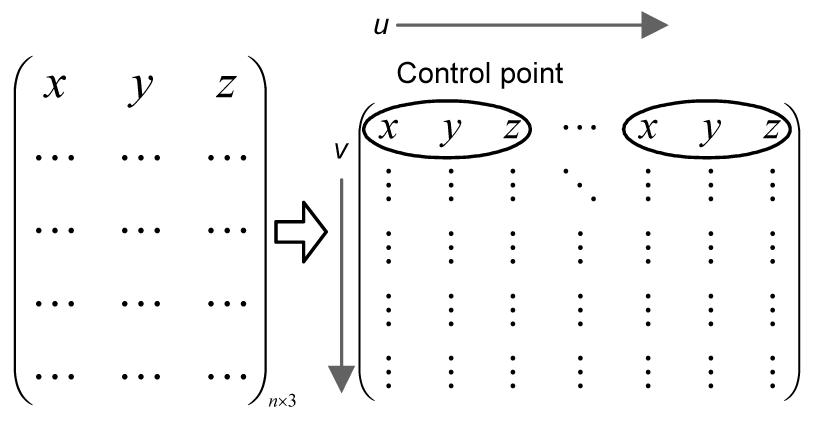
The control points of the NURBS surface are obtained from the scattered points (Fig. 2).
Fig.2 Converting scattered points cloud into NURBS surface control points
An elliptic cone is constructed by changing the node vector u of generatrix from a circle to an elliptic curve. An oblique cone is constructed from a right cone by changing the revolution axis. The tool envelope surface is generally defined as the maximum space of the tool during continuous machining. The maximum space can be approximated by an oblique elliptic cone using the NURBS envelope.
4. Obtaining per-vertex normal vectors and curvatures from per-triangulation normal vectors and curvatures on the triangular mesh
The curvatures at CC are obtained by fitting a moving least square (MLS) quadratic patch to the local neighborhood of a vertex and calculating eigenvectors and eigenvalues of the Hessian matrix. For the non-analytic surface, the principal curvature directions and values of a triangulated mesh are calculated. The faces and vertices structure data are rotated, so the normal of the current vertex becomes [−1, 0, 0]; thus, we can describe the data by XY instead of XYZ. Second, it fits an MLS quadratic patch to the local neighborhood of a vertex:.
Then the eigenvectors and eigenvalues of the Hessian matrix are used to calculate the principal direction, mean curvature H, and Gaussian curvature K. The Hessian matrix is the square matrix of second-order partial derivatives of a real-valued function; that is, it describes the local curvature of a function of many variables. The triangular face of the points set/surface is different from 2D or 3D Delaunay tessellation of points. The distance between point and surface can be obtained by computing the orthogonal projection of points onto the triangular faces.
Generally speaking, the normal vector has one definition while the curvature has many definitions. There is an indefinite number of curvatures at a point of surface (whether non-analytic or analytic). The triangulations intersect at the vertex. Obviously, there are an uncertain number of triangulations that intersect at the certain vertex. Therefore, it is difficult to obtain the normal vector and the curvature of each unique vertex from the normal vector and the curvature of each triangular surface. The normal vector at a point of the non-analytic surface is usually defined by the triangular faces, which makes the normal vector not unique. A normal vector and the curvature at a non-boundary point of a surface are all usually calculated from per-triangulation normal vectors and curvatures on the triangular mesh. The unique normal vector can generally be obtained using vector composition of the normal vectors calculated from various triangular faces shown in Fig. 3..
Fig.3 Per-vertex normal vectors and curvatures
The face-weighted per-vertex normal of the tessellated mesh in the faces, vertices format is calculated by averaging the non-normalized cross product for each triangle that touches a vertex. The per-vertex normal vector matrix is transformed into a sorted matrix first by sorting the point coordinates. The unique matrix that has no vertex repetitions of per-vertex normal vectors can be built. For each element in the unique matrix, the indices of the first and last occurrences of each unique value in the per-vertex normal vector matrix can be recorded and averaged. Then, the normal vector at all points can be found by summation of various vectors. The steps are as follows:
Step 1: Convert per-triangulation normal vectors and curvatures into matrix A using Eqs. (5), (6), and (18).
Step 2: Obtain unique vertices matrix X with no vertice repetitions.
Step 3: For each row of X, find the row index m1 (m1 must be a positive integer) which is the first occurrence of each unique value in A.
Step 4: For each row of X, find the row index m2 (m2 must be a positive integer) which is the last occurrence of each unique value in A.
Step 5: Obtain the mean value of the elements in A from m1 to m2.
Step 6: Obtain the per-vertex normal vectors and curvatures using Eq. (19).
5. Tool orientation smoothing according to the normal vector and curvature
Curves can be obtained not only by the connecting points set into a minimal nearest-neighbor closed curve/contour but also by the intersection between two homogeneous surfaces. A smooth curve is a G2 continuous curve (no gaps or discontinuities or superfluous inflection point or singular point) with no corners (no abrupt changes in slope at a point). A surface parameterized in variables u and v is considered smooth if the tangent vectors in the u and v directions satisfy cross product Tu×Tv≠0.
The 2D curve offset is used to generate equidistant curve textures in an area. A parallel of a curve is the envelope of a family of congruent circles centered on the curve. The parallel curves are at a fixed normal distance of a given curve. Small offset distances are usually used to ensure smooth curves; otherwise, kinks and doubled-back curves will occur. The weight according to curve curvature k at each point in the curve is employed by &ohgr;∝k to eliminate self-intersecting and overlapping:
where d is the Euclidean distance from the original curve, t is the curve variable and t∈[0, 1], and N(t) is the principal unit normal vector at the specified value t in curve, whose positive direction points to the concave side of the curve. Inner parallel (positive) is toward the center of curvature, and outer parallel is away from the center of curvature. At the curve inflection point, the unit principal normal vector N(t) is commonly difficult to solve.
The principal, mean, and Gaussian curvatures are normalized and mapped to the interval to determine the constraint space of the tool orientation. The ratio of curvature at CC to mean curvature of triangular facets is taken logarithm and absolute value to reduce the infinite ratio. The tool orientation Ot can be faired by optimizing the CL point Pcl from traditional normal direction n to the best direction with high cutting stiffness and collision avoidance. Whether the CL point is above its CC is judged by the dot product between the normal vector and the point on triangulation nearest to the CL point with Eq. (9) (Fig. 4):
where .
Fig.4 The point on triangulation nearest to the cutter location (CL)
Surface fairing means minimizing the surface energy E(S) of surface S, containing Ememb(S) which denotes energy of membrane and Ethin(S) which denotes energy of thin-plate:
6. Tool collision judgment by intersection between NURBS surfaces
Machining collision can be converted to intersection between graphics elements such as NURBS surface-surface or surface-curve. First, find an arbitrary point in the intersecting curve and find the next point in the gradient direction with a small step. The partial differentials can be approximated by partial difference and a point is considered as being in the intersecting curve if it meets the required accuracy.
The intersecting curve between NURBS surfaces can be calculated using the gradient vector as in Eq. (16):.
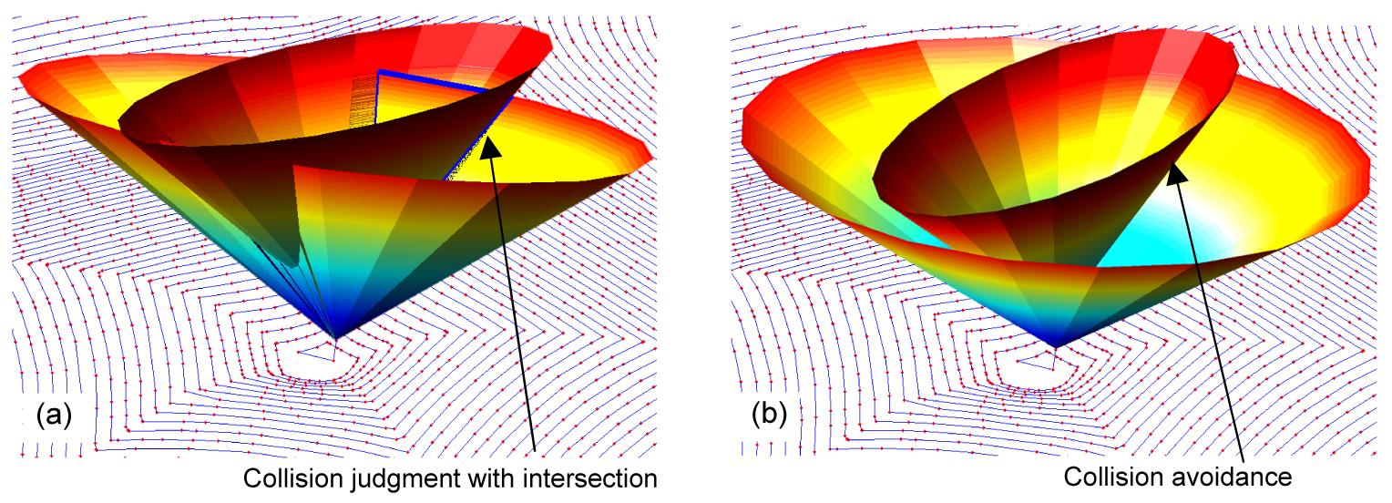
CL can be obtained from CC according to tool styles such as drum-like, torus, ball, flat, and bull end cutters. For each point in CC, the collision avoidance paths form an oblique elliptic cone where the tool orientation can be determined by the CL point shown in Fig. 5.
Fig.5 Cutter collision avoidance by tool orientation fairing: (a) collision with intersection; (b) chatter suppression and collision avoidance using tool orientation
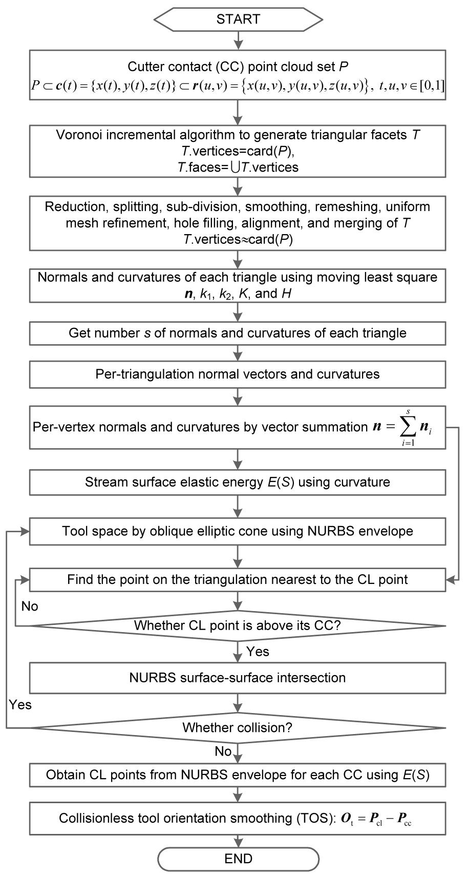
Fig. 6 shows the flowchart of the collisionless TOS above the stream surface based on the NURBS envelope.
Fig.6 Collisionless tool orientation smoothing (TOS) above the stream surface using the NURBS envelope
7. Application and experiments
7.1. Development of the prototype system
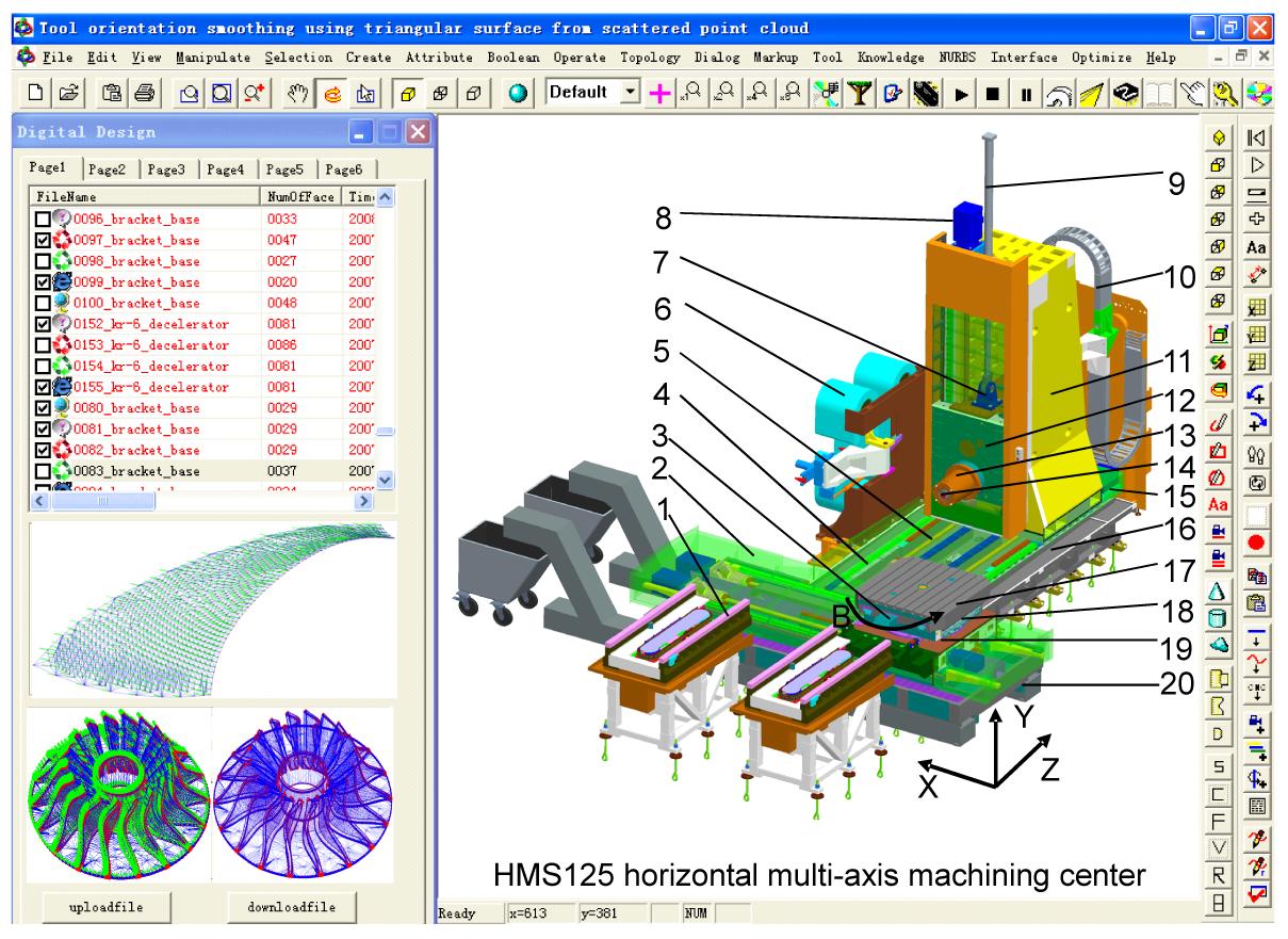
A kernel of stream surface machining for five-axis machining has been developed based on the proposed method (Fig. 7). The kernel is implemented with ACIS R13, HOOPS V11.0, C++, OpenGL version 2.0. The simulation module runs on Dell OptiPlex 790: Intel i5-2500 3.0 GHz and 4 GB RAM which is equipped with NVidia GT320M graphics accelerator GPU/CUDA.
Fig.7 The independent prototype system 1: loading and unloading material exchange station; 2: protective enclosure of linear guide; 3: optical encoder; 4: linear guide; 5: ballscrew; 6: tool magazine; 7: connecting base of the hydraulic cylinder; 8: servomotor; 9: counterbalance hydraulic cylinder; 10: pipes articulated chain; 11: column; 12: ram; 13: spindle; 14: tool clamping; 15: pseudo guide way; 16: longitudinal bed; 17: work table; 18: rotating frame; 19: sliding bottom; 20: horizontal bed
The scattered point cloud can be saved as binary stl (preferred), ASCII stl, obj, sat file, or iges/igs files. Stereolithography (STL) files are a common format for storing mesh data. STL meshes are simply a collection of triangular faces. The NC code includes many instruction blocks. The instruction block is composed of ISO letters and numbers such as G (address for preparatory commands), M (miscellaneous function), S (which defines speed, either spindle speed or surface speed, depending on mode), F (which defines feed rate), and T (tool selection). The tool orientation which is expressed by the coordinates of the two CL points is converted into an NC code automatically according to the postprocessor type of the machine center such as Siemens, Mikron, Heidenhain, Fanuc, Makino, and Mitsubishi.
7.2. Cutter orientation smoothing experiment
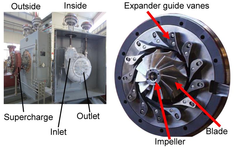
The experiment machine tool is a universal high speed five-axis machining center HMS125u: main spindle drive with 39 kW and 240 N∙m torque (18 000 r/min, HSK 63), solid machine base construction (gantry design), NC swiveling rotary table (clamping surface 1150 mm), workpiece weights up to 2000 kg, permitting swivel ranges from 30° to 115° (1°=60′=3600″=π/180 rad). This machining center allows for challenging milling and rotational machining in one clamping. The clamping surface has a diameter of 1000 mm and the nominal table load is 1000 kg. The workpiece is a cryogenic turboexpander impeller of air separation equipment which has a stream surface with varying curvatures (Figs. 8 and 9). To ensure high coaxiality and dynamic balance of the workpiece, the radial runout should be less than 0.2 mm and the face runout should be less than 0.5 mm. Such precise parts ordinarily would require the use of multi-axis and a variety of machining tools to complete.
Fig.8 Cryogenic turboexpander of the air separation equipment Fluid flow rate: 20 000 N∙m3/h; fluid: nitrogen (N2); mass flow rate: 6.98 kg/s; expansion efficiency: 82%; liquid hold-up 5%; temperature difference between shaft ends: 220 °C (inlet 40 °C, outlet −180 °C); inlet outlet pressure differential: inlet 2.75 MPa, outlet 3.95 MPa; impeller diameter: 108 mm; rotational speed: 27 000 r/min; maximum upstream pressure: 5 MPa; minimum downstream pressure: 1 MPa
Fig.9 Blade stream surface of the cryogenic turboexpander impeller
A turboexpander is a machine that continuously converts kinetic energy into mechanical energy. A cryogenic turboexpander is a centrifugal or axial flow turbine through which a high pressure fluid is expanded to produce work that is often used to drive a compressor. Turboexpanders have been very widely used as sources of refrigeration in air separation processes. Because work is extracted from the expanding high pressure fluid, the expansion is approximated by an isentropic process (i.e., a constant entropy process) and the low pressure exhaust gas from the turbine is at a very low temperature depending upon the operating pressure and fluid properties.
7.3. Comparison before and after using the proposed method
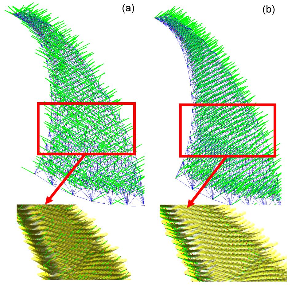
Figs. 10a and 10b show that the tool orientation is faired during self-intersected surface machining in multi-axis finish machining. The tool orientation vector before and after using the proposed method can be obtained from the supplementary material.
Fig.10 Tool orientation smoothing (TOS) before (a) and after (b) using NURBS envelope
Because the normal vectors have positive and negative values, we know that the surface is a self-intersected one. Although the blade stream surface is blending, the inside and outside surfaces are still precisely determined by using the NURBS envelope with Eq. (23). The surface roughness is greatly improved from Ra>0.41 μm to Ra<0.15 μm. The average absolute velocity of each axis is improved from 900 mm/min to 1200 mm/min. The machining time is shortened from 4000 s to 900 s.
8. Conclusions
The collisionless tool orientation smoothing (TOS) is realized with high machining stiffness using NURBS envelope. It is especially useful for blade stream surface machining whose normal direction may reverse into the minus direction
The precise curvatures at CC are obtained by fitting a moving least square (MLS) quadratic patch to the local neighborhood of a vertex and calculating eigenvectors and eigenvalues of the Hessian matrix
The partial differentials are approximated by partial difference to judge the surface intersection. The collisionless TOS is realized by NURBS envelope surface intersection operation
[1] Abele, E., Korff, D., 2011. Avoidance of collision-caused spindle damages—challenges, methods and solutions for high dynamic machine tools. CIRP Annals-Manufacturing Technology, 60(1):425-428.
[2] Balasubramaniam, M., Ho, S., Sarma, S., Adachi, Y., 2002. Generation of collision-free 5-axis tool paths using a haptic surface. Computer-Aided Design, 34(4):267-279.
[3] Balasubramaniam, M., Sarma, S.E., Marciniak, K., 2003. Collision-free finishing toolpaths from visibility data. Computer-Aided Design, 35(4):359-374.
[4] Beudaert, X., Pechard, P.Y., Tournier, C., 2011. 5-Axis tool path smoothing based on drive constraints. International Journal of Machine Tools and Manufacture, 51(12):958-965.
[5] Bi, Y.B., Cheng, Q.L., Dong, H.Y., Ke, Y.L., 2009. Machining distortion prediction of aerospace monolithic components. Journal of Zhejiang University-SCIENCE A, 10(5):661-668.
[6] Castagnetti, C., Duc, E., Ray, P., 2008. The domain of admissible orientation concept: a new method for five-axis tool path optimisation. Computer-Aided Design, 40(9):938-950.
[7] Chen, H.P., Kuo, H.H., Tsay, D.M., 2009. Removing tool marks of blade surfaces by smoothing five-axis point milling cutter paths. Journal of Materials Processing Technology, 209(17):5810-5817.
[8] Chen, K.H., 2011. Investigation of tool orientation for milling blade of impeller in five-axis machining. The International Journal of Advanced Manufacturing Technology, 52(1-4):235-244.
[9] Chiou, J.C.J., 2005. Optimal tool orientation for five-axis tool-end machining by swept envelope approach. Journal of Manufacturing Science and Engineering, 127(4):810-818.
[10] Chui, K.L., Chiu, W.K., Yu, K.M., 2008. Direct 5-axis tool-path generation from point cloud input using 3D biarc fitting. Robotics and Computer-Integrated Manufacturing, 24(2):270-286.
[11] Davim, P., 2012. Machining of Complex Sculptured Surfaces. Flank Milling of Complex Surfaces. Springer,Germany :
[12] de Lacalle, L.N.L., Lamikiz, A., Sanchez, J.A., Salgado, M.A., 2007. Toolpath selection based on the minimum deflection cutting forces in the programming of complex surfaces milling. International Journal of Machine Tools and Manufacture, 47(2):388-400.
[13] de Lacalle, L.N.L., Rodriguez, A., Lamikiz, A., Celaya, A., Alberdi, R., 2011. Five-axis machining and burnishing of complex parts for surface roughness improvement. Materials and Manufacturing Processes, 26(8):997-1003.
[14] Dombovari, Z., Iglesias, A., Zatarain, M., Insperger, T., 2011. Prediction of multiple dominant chatter frequencies in milling processes. International Journal of Machine Tools and Manufacture, 51(6):457-464.
[15] Fan, J., Ball, A., 2008. Quadric method for cutter orientation in five-axis sculptured surface machining. International Journal of Machine Tools and Manufacture, 48(7-8):788-801.
[16] Fard, M.J.B., Feng, H.Y., 2010. Effective determination of feed direction and tool orientation in five-axis flat-end milling. Journal of Manufacturing Science and Engineering, 132(6):061011
[17] Fard, M.J.B., Feng, H.Y., 2011. New criteria for tool orientation determination in five-axis sculptured surface machining. International Journal of Production Research, 49(20):5999-6015.
[18] Heinemann, R., Hinduja, S., 2012. A new strategy for tool condition monitoring of small diameter twist drills in deep-hole drilling. International Journal of Machine Tools and Manufacture, 52(1):69-76.
[19] Jin, G.Q., Li, W.D., Tsai, C.F., Wang, L., 2011. Adaptive tool-path generation of rapid prototyping for complex product models. Journal of Manufacturing Systems, 30(3):154-164.
[20] Kaneko, J., Horio, K., 2011. Tool posture planning method for continuous 5-axis control machining on machine tool coordinate system to optimize motion of translational axes. International Journal of Automation Technology, 5(5):729-737.
[21] Korakianitis, T., Hamakhan, I.A., Rezaienia, M.A., Wheeler, A.P.S., Avital, E.J., Williams, J.J.R., 2012. Design of high-efficiency turbomachinery blades for energy conversion devices with the three-dimensional prescribed surface curvature distribution blade design (circle) method. Applied Energy, 89(1):215-227.
[22] Lamikiz, A., de Lacalle, L.N., Sanchez, J.A., Salgado, M.A., 2005. Cutting force integration at the CAM stage in the high-speed milling of complex surfaces. International Journal of Computer Integrated Manufacturing, 18(7):586-600.
[23] Lauwers, B., Dejonghe, P., Kruth, J.P., 2003. Optimal and collision free tool posture in five-axis machining through the tight integration of tool path generation and machine simulation. Computer-Aided Design, 35(5):421-432.
[24] Lavernhe, S., Tournier, C., Lartigue, C., 2008. Kinematical performance prediction in multi-axis machining for process planning optimization. The International Journal of Advanced Manufacturing Technology, 37(5-6):534-544.
[25] Morishige, K., Kase, K., Takeuchi, Y., 1997. Collision-free tool path generation using 2-dimensional C-space for 5-axis control machining. The International Journal of Advanced Manufacturing Technology, 13(6):393-400.
[26] Park, S.C., Chang, M., 2010. Tool path generation for a surface model with defects. Computers in Industry, 61(1):75-82.
[27] Pekerman, D., Elber, G., Kim, M.S., 2008. Self-intersection detection and elimination in freeform curves and surfaces. Computer-Aided Design, 40(2):150-159.
[28] Radzevich, S.P., 2006. A closed-form solution to the problem of optimal tool-path generation for sculptured surface machining on multi-axis NC machine. Mathematical and Computer Modelling, 43(3-4):222-243.
[29] Shan, Y., Wang, S.L., Tong, S.G., 2000. Uneven offset method of NC tool path generation for free-form pocket machining. Computers in Industry, 43(1):97-103.
[30] Shen, H.Y., Fu, J.Z., He, Y., Yao, X.H., 2012. On-line asynchronous compensation methods for static/quasi-static error implemented on CNC machine tools. International Journal of Machine Tools and Manufacture, 60:14-26.
[31] Takeuchi, Y., Watanabe, T., 1992. Generation of 5-axis control collision-free tool path and postprocessing for NC data. CIRP Annals-Manufacturing Technology, 41(1):539-542.
[32] Tournier, C., Duc, E., 2002. A surface based approach for constant scallop height tool-path generation. The International Journal of Advanced Manufacturing Technology, 19(5):318-324.
[33] Vahebi Nojedeh, M., Habibi, M., Arezoo, B., 2011. Tool path accuracy enhancement through geometrical error compensation. International Journal of Machine Tools and Manufacture, 51(6):471-482.
[34] Vijayaraghavan, A., Sodemann, A., Hoover, A., Mayor, J.R., David, D., 2010. Trajectory generation in high-speed, high-precision micromilling using subdivision curves. International Journal of Machine Tools and Manufacture, 50(4):394-403.
[35] Wang, G., Shan, Y., 2005. Compensation of electrode orbiting in electrical discharge machining based on non-uniform offsetting. International Journal of Machine Tools and Manufacture, 45(14):1628-1634.
[36] Xu, J.H., Zhang, S.Y., Tan, J.R., Liu, X.J., 2012. Non-redundant tool trajectory generation for surface finish machining based on geodesic curvature matching. The International Journal of Advanced Manufacturing Technology, 62(9-12):1169-1178.
Open peer comments: Debate/Discuss/Question/Opinion


Open peer comments: Debate/Discuss/Question/Opinion
<1>