Affiliation(s):
1.
School of Civil Engineering and Mechanics, Huazhong University of Science and Technology, Wuhan 430074, China; moreAffiliation(s): 1.
School of Civil Engineering and Mechanics, Huazhong University of Science and Technology, Wuhan 430074, China; 2.
Hubei Key Laboratory of Control Structure, Huazhong University of Science and Technology, Wuhan 430074, China; less
Xiao Huang, Hong-ping Zhu. Optimal arrangement of viscoelastic dampers for seismic control of adjacent shear-type structures[J]. Journal of Zhejiang University Science A, 2013, 14(1): 47-60.
@article{title="Optimal arrangement of viscoelastic dampers for seismic control of adjacent shear-type structures", author="Xiao Huang, Hong-ping Zhu", journal="Journal of Zhejiang University Science A", volume="14", number="1", pages="47-60", year="2013", publisher="Zhejiang University Press & Springer", doi="10.1631/jzus.A1200181" }
%0 Journal Article %T Optimal arrangement of viscoelastic dampers for seismic control of adjacent shear-type structures %A Xiao Huang %A Hong-ping Zhu %J Journal of Zhejiang University SCIENCE A %V 14 %N 1 %P 47-60 %@ 1673-565X %D 2013 %I Zhejiang University Press & Springer %DOI 10.1631/jzus.A1200181
TY - JOUR T1 - Optimal arrangement of viscoelastic dampers for seismic control of adjacent shear-type structures A1 - Xiao Huang A1 - Hong-ping Zhu J0 - Journal of Zhejiang University Science A VL - 14 IS - 1 SP - 47 EP - 60 %@ 1673-565X Y1 - 2013 PB - Zhejiang University Press & Springer ER - DOI - 10.1631/jzus.A1200181
Abstract: The optimal arrangement of viscoelastic dampers (VEDs) used to link two adjacent shear-type structures under seismic excitation was investigated. A two-step optimal design method is proposed. First, optimal parameter expressions of the Kelvin model are used to calculate the optimal stiffness and damping coefficient of the VEDs. Then, using the two-step optimal design method, taking the quadratic performance index as the optimization objective, the optimal arrangement of the dampers is determined. General rules about the optimal arrangement of the VEDs were obtained. The results show that the placement of only one damper between two adjacent shear-type structures should be avoided; if more than one damper is used, they should be distributed on the top and lower floors of the structures. Optimization of the number of dampers had little effect on response reduction. The most important factor was the optimization of the placement of the dampers. Through comparative study, for buildings of equal and unequal heights, the optimal parameters of dampers from parametric studies were shown to match the theoretical results for different numbers and placements of dampers. The level of response reduction was shown to be sensitive to the damping coefficient of the dampers.
Darkslateblue:Affiliate; Royal Blue:Author; Turquoise:Article
Article Content
1. Introduction
With rapid economic development, there are more large and high buildings in modern cities, resulting in inadequate separation between adjacent buildings. When two closely spaced adjacent structures are subjected to strong earthquakes, they may collide (Kasai and Maison, 1997; Abdullah et al., 2001). Using energy dissipation devices to connect adjacent structures has proved to be an effective measure to avoid collisions between such buildings and to absorb some seismic energy (Bhaskararao and Jangid, 2006a; 2006b; 2006c; Takewaki, 2007; Bharti et al., 2010; Patel and Jangid, 2011; Roh et al., 2011). Passive control devices are efficient for energy dissipation (Lavan and Levy, 2006; Trombetti and Silvestri, 2006; Silvestri and Trombetti, 2007). Trombetti and Silvestri (2007) investigated the applicability of a novel scheme for inserting viscous dampers in shear-type systems, and provided insights for the effective addition of viscous dampers in mechanical dynamic systems. Viscoelastic dampers (VEDs) are an efficient kind of passive control device for suppressing vibration and dissipating energy, with the advantages of simple installation, low cost and stable performance. There has been a series of studies on adjacent structures coupled with VEDs under seismic excitation. Xu et al. (1999) carried out a theoretical investigation of earthquake-resistance performance of adjacent buildings connected by VEDs defined by the Kelvin model, and obtained the optimal parameters of dampers through extensive parametric studies. Kim et al. (2006) investigated the effect of installing VEDs in places such as seismic joints or building-sky-bridge connections, and found that the displacements of structures were significantly reduced. Zhu and Iemura (2000) studied 2-single-degree-of-freedom (SDOF) structures connected by VED under white noise excitation, and gave the analytical formulas for determining the optimal parameters of VED, which were determined from the mass ratio and the natural frequency ratio of 2-SDOF structures. Zhu et al. (2011) and Ge et al. (2010) extended the analytical formulas based on 2-SDOF structures to those of 2-multiple-degree-of-freedom (MDOF) structures, and found that total optimal parameters of VEDs between 2-MDOF structures were determined by the total mass ratio and the modal frequency ratio of the structures. Thus, the total optimal parameters of VEDs between 2-MDOF structures can be directly calculated using theoretical expressions. However, the controlling effect of dampers depends not only on the optimization of the output forces, but also on the placement of the dampers. Where and how many dampers are placed on the structures will have a significant effect on their ability to reduce the responses of structures (Singh and Moreschi, 2002). Ok et al. (2008) studied the optimal design of hysteretic dampers that enhance the seismic performance of two adjacent structures. However, there have been few studies of the optimal arrangement of VEDs between adjacent structures. In previous studies, dampers have generally been placed on one floor (Kim et al., 2006) or uniformly placed on all floors (Xu et al., 1999; Ge et al., 2010; Zhu et al., 2011). According to Zhu et al. (2011), the total optimal parameters of VEDs can be easily obtained. If general methods for determining the optimal arrangement of dampers can also be defined, this will be very useful for the application of VEDs.
The optimal arrangement of VEDs between adjacent structures under seismic excitation was investigated. A two-step optimal design method is proposed. Optimal parameter expressions of VEDs were used to calculate the optimal stiffness and damping coefficients of VEDs. Using the two-step optimal design method, first the number of dampers was assumed to be a certain value, and an enumeration method was used to deal with their optimal placement; then by a comparison method, the number of dampers was optimized. General rules for the optimal arrangement of dampers were obtained based on the above studies, enabling engineers to select directly the optimal parameters and arrangements of VEDs.
2. Problem formulation
2.1. Equation of motion
The 2-MDOF buildings are assumed to be symmetric with their symmetric planes aligned. The ground motion is assumed to excite in the symmetric planes of the buildings, so that the problem can be simplified as a 2D problem. Due to the added dampers, the energy absorbing capacity of the buildings is enhanced, so buildings are assumed to remain in a linear elastic state.
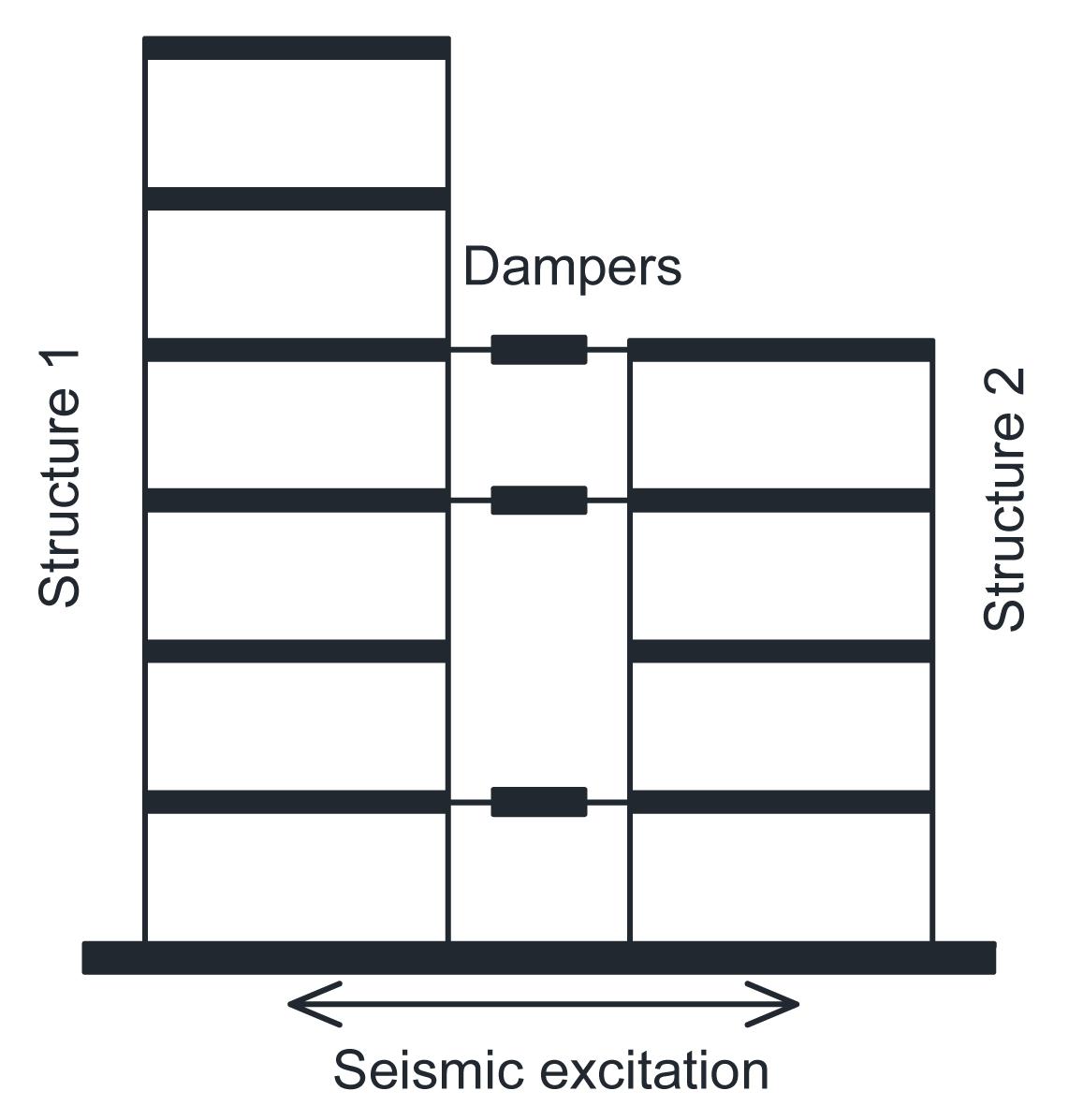
Fig. 1 illustrates a structural system consisting of two adjacent shear-type structures with n1 and n2 storeys, connected by VEDs at some storeys. The research was focused on adjacent shear-type structures, i.e., structures for which shear-type behavior is predominant with respect to flexural-type deformation. The VED is represented by the Kelvin model; that is, a linear spring and a viscous dashpot are combined in parallel. The force-deformation relationship of the VED is expressed as follows:
,
where kd and cd are the stiffness and damping coefficients of the damper, respectively, and and are the relative displacement and relative speed respectively, between the two damper ends.
Fig.1 Simplified model of adjacent structures
The equation of motion of the coupled structural system under seismic excitation can be written as ,
where M, K and C are n×n (n=n1+n2) dimensional mass, stiffness, and internal damping matrices of the adjacent buildings, respectively; X(t) is the n dimensional relative displacement vector with respect to the ground; U(t) is the damper force vector; H is the location matrix of the dampers; is the acceleration of ground motion; and I is the n dimensional unit vector.
2.2. Control strategy
To numerically identify optimized systems of added VEDs, as applied to shear-type structures, it is necessary to introduce a constraint upon the total size of the added VEDs, and to select a control index capable of capturing the overall dissipative capacity of the system.
Supposing only one damper is installed on each floor. The total amount of dampers, s, can be changed from 1 to m where m is the total number of storeys of the lower structure. The constraints of the optimization problem are the equal total stiffness kdopt and equal total damping coefficient cdopt of the VEDs, which can be calculated directly using optimal parameter expressions (section 3). The above constraint mathematically translates into the following formula:
.
The aim of the control strategy is to reduce the motion of the adjacent structures as much as possible. The total vibration energy of the adjacent structures is chosen as the objective function, similar to the quadratic performance index of a linear control system. This objective can be achieved by minimizing the total vibration energy of the coupled structures at entire time steps during seismic excitations. Suppose that the objective function is denoted by D. The optimal arrangement problem of dampers can be described by the following mathematical formula:
,
where te is the duration of the ground motion.
3. Optimal parameter expressions of VEDs
3.1. Reduced order model of adjacent structures
To approximate the motion of structure 1 or 2 (Fig. 1) with a SDOF, assume that the deformation is in only a single shape (Clough and Penzien, 2004). The shape functions of structures 1 and 2 are designated &PSgr;i (i=1, 2), which must satisfy the displacement boundary conditions. The amplitude of the motion relative to the moving base is represented by the generalized coordinate zi(t), which represents the generalized displacements. Thus,.
By the principle of virtual displacement, the generalized SDOF system of structure 1 or 2 is obtained (Clough and Penzien, 2004; Basili and De Angelis, 2007). The generalized equation of motion is expressed as follows:,
where i=1, 2, and are the generalized mass and generalized stiffness of structure i. , , , ; Mi, Ki and Ci are the mass, stiffness, and damping matrices of structure i; and Ii is a unit vector.
Considering a model of 2-SDOF structures (Fig. 2) connected by a VED, the equations of motion are written as, ,
where mi and &xgr;i are the total mass and the first modal damping ratio of structure i, respectively; , , , i=1,2; and is the output force of a VED.
Fig.2 2-SDOF structures linked by VED
3.2. Optimal parameters of VEDs
Zhu et al. (2011) regarded two adjacent structures as 2-SDOF systems, and represented the VED by the Kelvin model. The optimal parameters of the VED are determined under the two objectives that minimize the vibration energy of the primary structure or the total vibration energy of two adjacent structures under stationary white-noise ground motion. In this study, structures 1 and 2 are equally important, and the control target is minimization of the total vibration energy of the two structures. Structure 1, whose stiffness is lager, is seen as the main structure; structure 2 is seen as a secondary structure. The modal frequency ratio of structure 2 to structure 1 is represented by β, and β should be no more than 1; if β>1, the roles of structures 1 and 2 must be exchanged. The optimal stiffness coefficient βopt and optimal damping coefficient &Dgr;opt have the following expressions:
when μ<1,;
when μ≥1,
where μ=m1/m2 is the total mass ratio of structure 1 to structure 2, and β=ω2/ω1 is the modal frequency ratio of structure 2 to structure 1. In fact, ω1 and ω2 are the best approximate results of the lowest frequencies of structures 1 and 2, since the generalized-coordinate concept is used to reduce the structure to a SDOF. As the first vibration mode is dominant in the horizontal movement of the structure, the first order mode shape is chosen as the shape function in this study. The total optimal parameters of stiffness and damping are expressed as
.
The total optimal coefficients of VEDs interconnecting 2-MDOF structures are obtained by optimal parameter expressions. Then, the total optimal coefficients should be divided among the dampers. Suppose the attributes of the dampers are identical. On each floor, only one damper is installed, and the total amount of dampers is s. The optimal stiffness and optimal damping coefficients of each damper are kdopt/s and cdopt/s, respectively.
4. Optimal arrangement of VEDs
The following two pairs of adjacent shear-type structures are considered. Structure 1 is a 10-storey building; structure 2 is either a 10-storey or 16-storey building. All structures are considered as linear MDOF flexible shear-type structures with lumped mass at the floor levels.
Example 1: Structures 1 and 2 are equal-height buildings and both are 10 storeys, with the same floor elevations. The mass and shear stiffness of structures 1 and 2 are uniform for each storey. For structure 1, the mass of each storey is 1.35×10⁶ kg, and the shear stiffness is 1.96×10⁹ N/m. For structure 2, the mass of each storey is 1.18×10⁶ kg, and the shear stiffness is 8.3×10⁸ N/m. Rayleigh proportional damping is used, and the first and second modal damping ratios of each structure are 0.02. The first natural frequencies of structures 1 and 2 are 5.69 and 3.96 rad/s, respectively. Using optimal parameter expressions, the total optimal stiffness is 7.07×10⁶ N/m, and the total optimal damping is 1.5×10⁷ N∙s/m.
Example 2: Structures 1 and 2 are unequal height buildings. The parameters of structure 1 are the same as those of Example 1. Structure 2 is a 16-storey building; the mass of each storey is 1.56×10⁶ kg, and the shear stiffness of each storey is 3.0×10⁹ N/m. Using optimal parameter expressions, the total optimal stiffness is 0, and the total optimal damping is 2.04×10⁷ N∙s/m.
Two earthquake records are used: the NS components of the 1940 EI Centro record and the N21E components of the 1952 Taft earthquake. The maximum acceleration is scaled to 0.2g.
4.1. Two-step optimal design method
After the total optimal parameters of the dampers have been determined, the optimal arrangement of the dampers must be solved, as this may have an effect on their ability to reduce the responses of the structures. A two-step optimal design method is used to solve the optimization problem. The first step is to obtain the optimal placement of the dampers. The second step is to obtain the optimal number of dampers.
In the first step, assume that the number of dampers is a certain value, denoted by s. s should change from 1 to m where m is the total number of storeys in the lower structure. For each case, there are
kinds of different combinations of the dampers. Then, calculate the quadratic performance index for each kind of combination of dampers. By comparison, select the combination of dampers which minimizes the corresponding value of the quadratic performance index as the optimal placement of dampers. In this step, an enumeration method is used and all kinds of combinations of the dampers are considered. If an artificial intelligence algorithm is used, the optimal placement of dampers can only be searched and the general rules about the optimal placement of dampers cannot be obtained. Thus, an enumeration method, using numerous calculations, is used to deal with the optimal placement of dampers.
In the second step, select the number of dampers for which the corresponding value of the quadratic performance index is the minimum, and that is the optimal number of dampers. Through these two steps, the optimal arrangement of dampers, including the optimal placement and optimal number of dampers, can be solved. What’s more, some useful rules about the optimal arrangement of dampers can be obtained.
4.2. Optimal placement of dampers
Now the first step of the two-step optimal design method is used to obtain the optimal placement of the dampers for different numbers of dampers. In Example 1, the total vibration energy of the two structures with the change of placement of the dampers under two different earthquakes excitations are as follows.
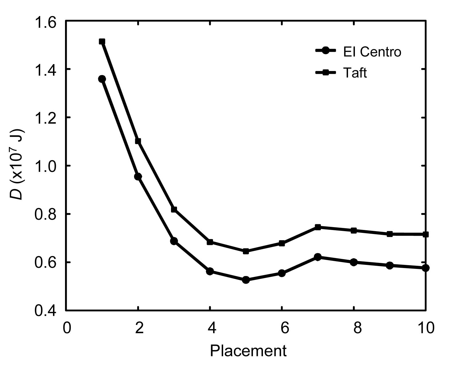
When only one damper is placed between the two structures, there are a total of 10 different placements. Fig. 3 shows that the total vibration energy of the two structures changes with the placement of the damper under EI Centro and Taft earthquake excitation. In Fig. 3, ‘placement 1’ represents placement of the damper on the first floor; ‘placement 2’ represents placement on the second floor, and so on. When the placement of the damper is changed from the first floor to the tenth floor, the total vibration energy of the two structures decreases quickly in the lower floors and then slightly increases, and shows little change in the upper floors. Thus, if there is only one damper, it should be placed on the upper floors of the structures. When the damper is placed on the fifth floor, the control effect of the damper is the best, and the values of D are 5.28×10⁶ J and 6.35×10⁶ J, respectively; when the damper is placed on the first floor, the control effect of the damper is the worst, and the values of D are 1.36×10⁷ J and 1.51×10⁷ J, 2.57 times and 2.38 times the respective values for placement on the fifth floor.
Fig.3 Total relative vibration energy changes with placement of dampers (one damper)
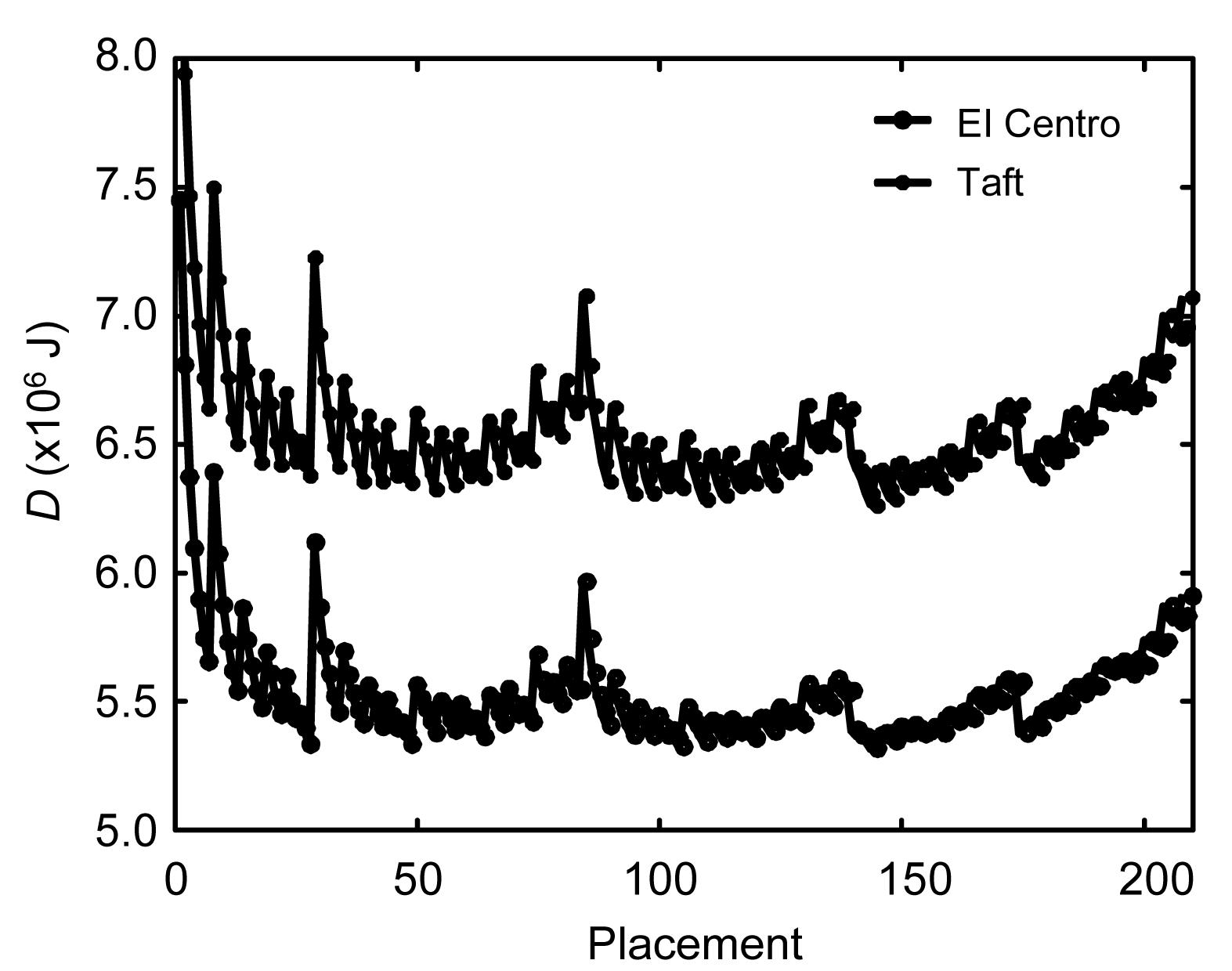
When four dampers are placed between the two structures, there are 210 different placement combinations of dampers. Fig. 4 shows that the total vibration energy of the two structures changes with the placement combinations of dampers under EI Centro and Taft earthquake excitation. In Fig. 4, ‘placement 1’ represents placement of dampers on the first, second, third and fourth floors, denoted by ‘1, 2, 3, 4’; “placement 2” represents ‘1, 2, 3, 5’, and so on. The optimal placement is ‘2, 3, 9, 10’ for both earthquakes, and the values of D are 5.32×10⁶ J and 6.26×10⁶ J, respectively. When the placement of dampers is ‘1, 2, 3, 4’, the control effect is the worst, and the values of D are 7.45×10⁶ J and 8.65×10⁶ J, 1.40 times and 1.38 times the respective values for the optimum placement. There are some peak values in the curves of Fig. 4, for which the corresponding placements are ‘1, 2, 3, 4’, ‘1, 2, 4, 5’, ‘1, 3, 4, 5’, ‘2, 3, 4, 5’ and ‘7, 8, 9, 10’. So, when dampers are placed centrally on the lower or upper floors, the control effect is reduced; thus, the control effect of the dampers which are distributed on the top and lower floors is better than that of centrally placed dampers.
Fig.4 Total relative vibration energy changes with placement of dampers (four dampers)
When seven dampers are placed between the two structures, there are 120 different placement combinations of dampers. Fig. 5 shows that the total vibration energy of the two structures changes with placement of dampers under EI Centro and Taft earthquake excitation. ‘Placement 1’ represents ‘1, 2, 3, 4, 5, 6, 7’; ‘placement 2’ represents ‘1, 2, 3, 4, 5, 6, 8’, and so on. The optimal placements are ‘2, 3, 4, 5, 7, 9, 10’ and ‘2, 3, 4, 5, 6, 9, 10’ for the two earthquakes with little difference between them, and the values of D are 5.38×10⁶ J and 6.31×10⁶ J respectively. When the placement of dampers is ‘4, 5, 6, 7, 8, 9, 10’, the control effect is the worst, and the corresponding values of D are 5.61×10⁶ J and 6.62×10⁶ J, only 1.04 times and 1.05 times the respective optimal placements. By comparing these three conditions, we conclude that the higher is the number of dampers, the smaller is the difference in the control effect between the optimal and the worst placements of dampers. That is, optimal placement of dampers is more important when fewer dampers are used.
Fig.5 Total relative vibration energy changes with placement of dampers (seven dampers)
4.3. Optimal number of dampers
On the premise of the above results, the second step of the two-step optimal design method is conducted. For different numbers of dampers, Tables 1 and 2 list the optimization results, the corresponding values of D, and the ratios of D when the worst and the optimal placements are considered. The optimal placements of dampers are all distributed placements on the top and lower floors corresponding to different numbers of dampers. The ratio of D decreases with the increase in the number of dampers; that is, the difference in the control effect between the optimal and the worst placements of dampers is smaller when more dampers are used. Under the two kinds of earthquakes, there is a slightly difference in the optimization results. This is very favorable for the application of the VEDs.
Table 1
Results of placement optimization (Example 1)
Number
Optimization results
Value of D (J)
Ratio of D
EI Centro
Taft
EI Centro
Taft
EI Centro
Taft
1
5
5
5.28×10⁶
6.35×10⁶
2.57
2.38
2
2,10
2,10
5.26×10⁶
6.22×10⁶
2.11
2.01
3
3,4,10
3,4,10
5.30×10⁶
6.25×10⁶
1.70
1.65
4
2,3,9,10
2,3,9,10
5.32×10⁶
6.26×10⁶
1.40
1.38
5
2,3,4,9,10
2,3,4,9,10
5.33×10⁶
6.29×10⁶
1.21
1.20
6
2,3,4,5,9,10
2,3,4,5,9,10
5.35×10⁶
6.30×10⁶
1.10
1.06
7
2,3,4,5,7,9,10
2,3,4,5,6,9,10
5.38×10⁶
6.31×10⁶
1.04
1.05
8
1,2,3,4,5,8,9,10
1,2,3,4,5,6,9,10
5.39×10⁶
6.34×10⁶
1.02
1.02
9
1,2,3,4,5,6,8,9,10
1,2,3,4,5,6,8,9,10
5.40×10⁶
6.35×10⁶
1.01
1.01
10
1,2,3,4,5,6,7,8,9,10
1,2,3,4,5,6,7,8,9,10
5.42×10⁶
6.38×10⁶
1.00
1.00
Table 2
Results of placement optimization (Example 2)
Number
Optimization results
Value of D (J)
Ratio of D
EI Centro
Taft
EI Centro
Taft
EI Centro
Taft
1
7
7
9.59×10⁶
1.56×10⁷
4.60
3.50
2
5,10
3,10
9.25×10⁶
1.42×10⁷
3.66
3.09
3
3,5,10
3,5,10
9.24×10⁶
1.41×10⁷
2.77
2.45
4
4,5,9,10
3,5,9,10
9.26×10⁶
1.42×10⁷
2.12
1.93
5
4,5,6,9,10
3,4,5,9,10
9.27×10⁶
1.43×10⁷
1.70
1.58
6
4,5,6,8,9,10
3,4,5,8,9,10
9.28×10⁶
1.44×10⁷
1.42
1.36
7
4,5,6,7,8,9,10
2,3,4,5,8,9,10
9.30×10⁶
1.45×10⁷
1.24
1.19
8
3,4,5,6,7,8,9,10
2,3,4,5,6,8,9,10
9.33×10⁶
1.46×10⁷
1.13
1.08
9
2,3,4,5,6,7,8,9,10
2,3,4,5,6,7,8,9,10
9.43×10⁶
1.47×10⁶
1.05
1.04
10
1,2,3,4,5,6,7,8,9,10
1,2,3,4,5,6,7,8,9,10
9.60×10⁶
1.48×10⁷
1.00
1.00
From the placement optimization results, for Example 1, the optimal number of dampers is two, and their optimal placement is on the second and tenth floors; for Example 2, the optimal number of dampers is three, and their optimal placement is on the third, fifth and tenth floors. But for different numbers of dampers, when optimal placements are made, the levels of reduction in total vibration energy are nearly the same. So, optimization of the number of dampers has little effect on the control performance of dampers, and optimization of the placement of a certain number of the dampers is the most important.
4.4. Optimal parameters of VEDs
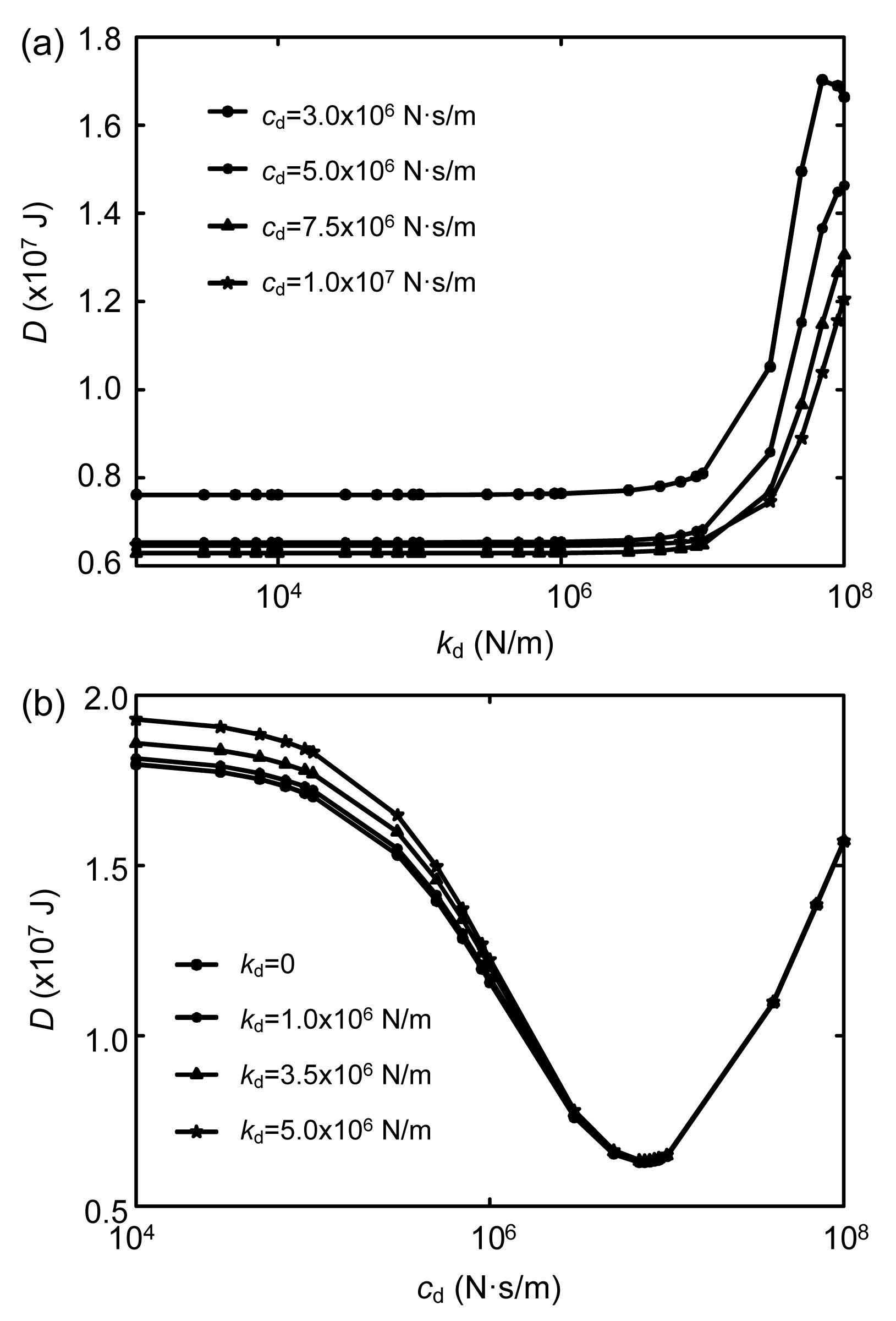
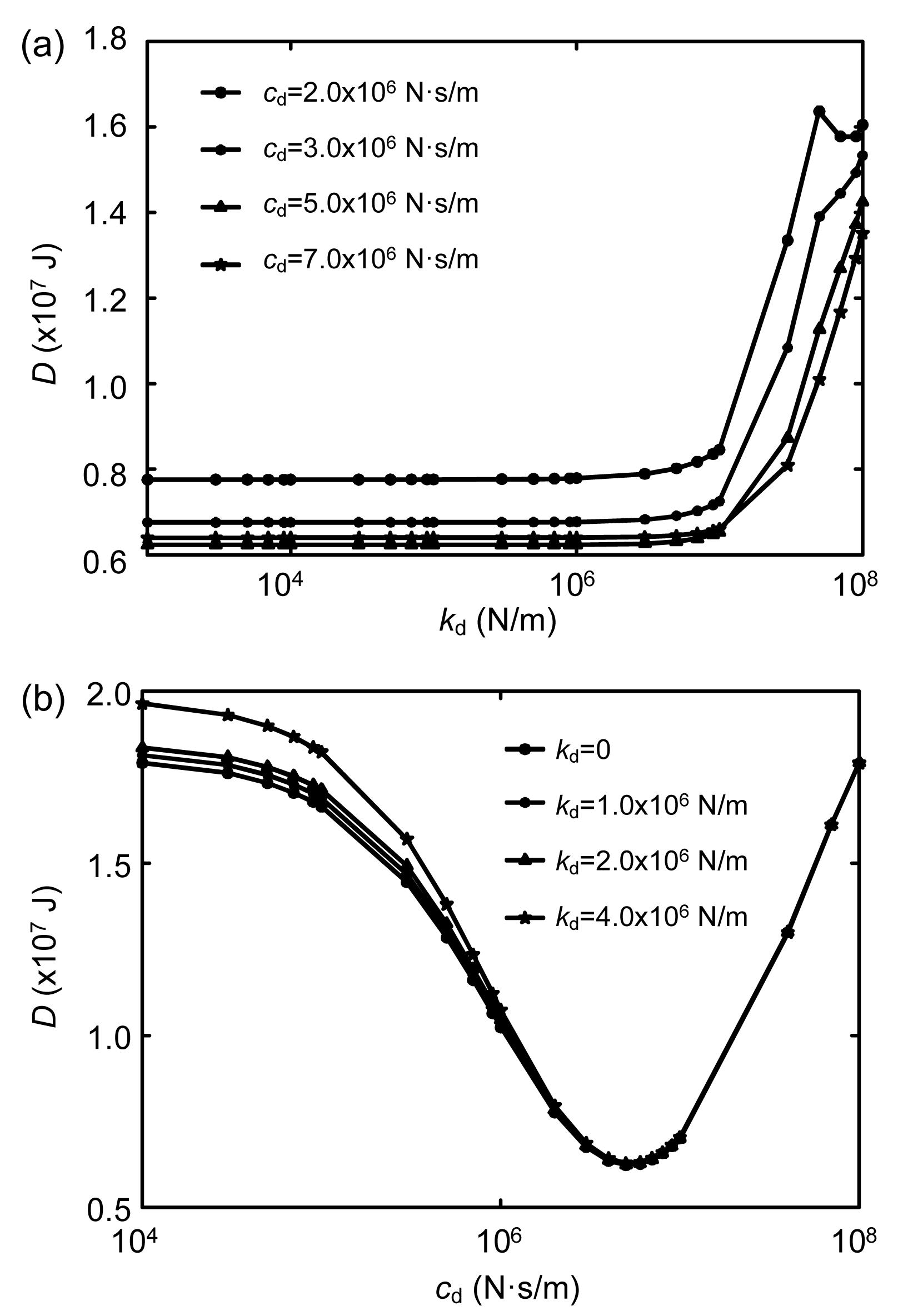
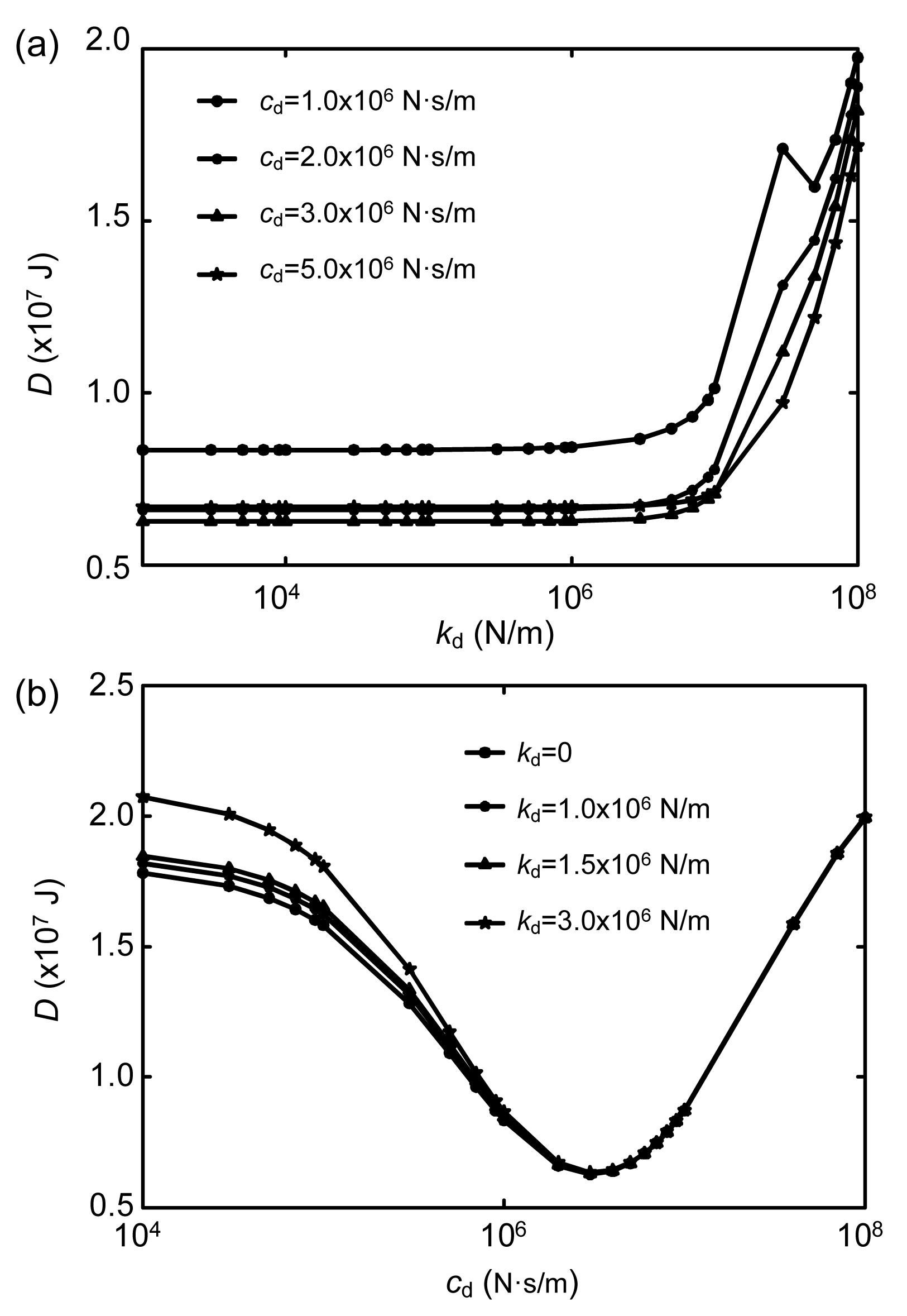
For Example 1, Fig. 6 shows the variations in total vibration energy of two structures with stiffness kd and damping coefficient cd of a VED under the Taft earthquake excitation, when one damper is placed on each of the second and tenth floors. The sum of the stiffness and damping coefficient of the dampers are 2kd and 2cd, respectively. When the stiffness kd is less than 5.0×10⁶ N/m, the effect of the stiffness on the performance of the dampers is negligible; but when the stiffness kd is more than 5.0×10⁶ N/m, the control performance of the dampers soon deteriorates (Fig. 6a). So the linear spring of the VED has little positive effect on the response reduction of the structures. In Fig. 6b, the optimal damping coefficient cd is 7.5×10⁶ N∙s/m, and the level of response reduction is sensitive to the value of the optimal damping coefficient cd. The theoretical results of the optimal stiffness kd and damping coefficient cd are 7.07×10⁶/2=3.54×106 N/m and 1.5×10⁷/2=7.5×106 N∙s/m, respectively. Thus, the optimal values from the parametric studies are consistent with the theoretical results based on the 2-SDOF damper system. Fig. 7 shows the variations in total vibration energy of two structures with stiffness kd and damping coefficient cd of the VED under the Taft earthquake excitation, when one damper is placed on each of the third, fourth and tenth floors. When the stiffness kd is less than 3.0×10⁶ N/m, the effect of the stiffness on the performance of the dampers is negligible (Fig. 7a). The optimal damping coefficient cd is 5.0×10⁶ N∙s/m (Fig. 7b). The theoretical results for the optimal stiffness kd and damping coefficient cd are 7.07×10⁶/3 =2.36×10⁶ N/m and 1.5×10⁷/3=5.0×106 N∙s/m, respectively. The optimal values from the parametric studies are consistent with the theoretical results. Fig. 8 shows the variations in total vibration energy of the two structures with stiffness kd and damping coefficient cd of the VED under the Taft earthquake excitation, when one damper is placed on each of the second, third, fourth, ninth and tenth floors. When the stiffness kd is less than 2.0×10⁶ N/m, the effect of the stiffness on the performance of the dampers is negligible (Fig. 8a). The optimal damping coefficient cd is 3.0×10⁶ N∙s/m (Fig. 8b). The theoretical results for the optimal stiffness kd and damping coefficient cd are 7.07×10⁶/5=1.41×106 N/m and 1.5×10⁷/5=3.0×106 N∙s/m, respectively. The optimal values from the parametric studies are again consistent with the theoretical results.
Fig.6 Vibration energy of two structures changes with stiffness (a) and damping coefficient (b) of VED (two dampers) under the Taft earthquake excitation
Fig.7 Vibration energy of two structures changes with stiffness (a) and damping coefficient (b) of VED (three dampers) under the Taft earthquake excitation
Fig.8 Vibration energy of two structures changes with stiffness (a) and damping coefficient (b) of VED (five dampers) under the Taft earthquake excitation
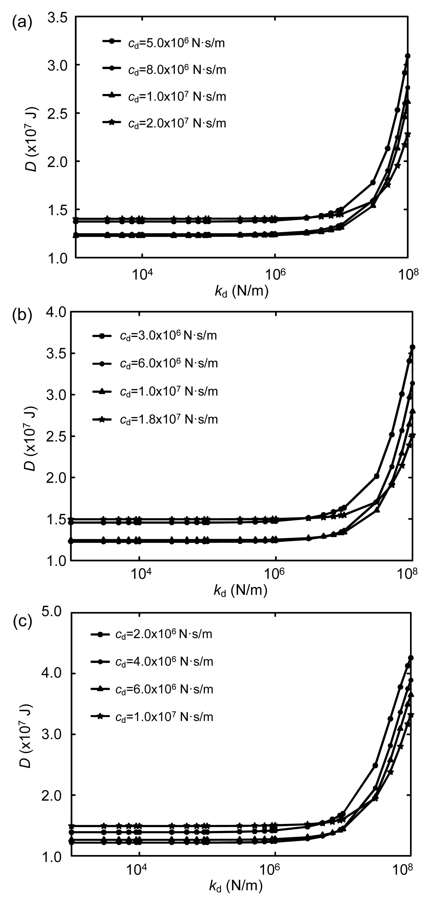
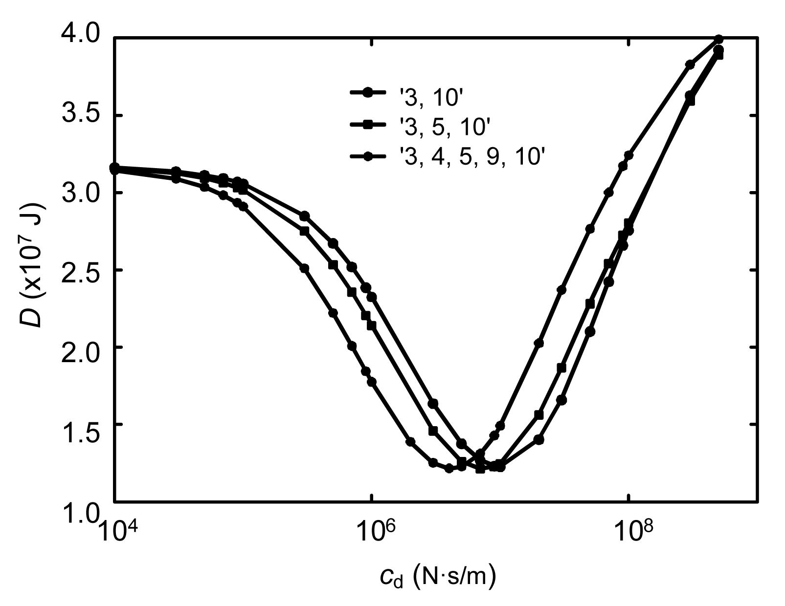
For Example 2, Fig. 9 shows the variations in total vibration energy of two structures with stiffness kd under the Taft earthquake excitation, when two, three or five dampers are placed between two adjacent structures. For two dampers, one is placed on the third floor and the other on the tenth floor; for three dampers, one is placed on each of the third, fifth and tenth floors; for five dampers, one is placed on each of the third, fourth, fifth, ninth and tenth floors. When the stiffness kd is less than 1.0×10⁶ N/m, the effect of the stiffness on the performance of the dampers is negligible. So the optimal stiffness of the VEDs can be taken as 0, and this is consistent with the theoretical result. Fig. 10 shows the variations in total vibration energy of two structures with damping coefficient cd of a VED under the Taft earthquake excitation, when stiffness kd is 0. The optimal damping coefficients cd are 1.0×10⁷ N∙s/m, 7.0×10⁶ N∙s/m and 4.0×10⁶N∙s/m. The theoretical results are 2.04×10⁷/2=1.02×107 N∙s/m, 2.04×10⁷/3=6.80×106 N∙s/m and 2.04×10⁷/5=4.08×106 N∙s/m, respectively. So it can be concluded that for buildings with equal or unequal height, the optimal values from the parametric studies are all consistent with the theoretical results based on the 2-SDOF damper system with different numbers and placements of dampers.
Fig.9 Variations of total vibration energy of two structures with stiffness of VED under the Taft earthquake excitation (a) Two dampers; (b) Three dampers; (c) Five dampers
Fig.10 Variations of total vibration energy of two structures with damping coefficient of VED under the Taft earthquake excitation
5. Performance of VEDs
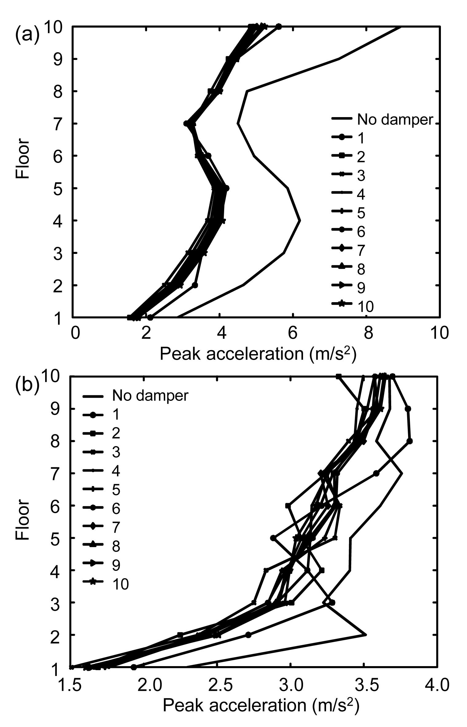
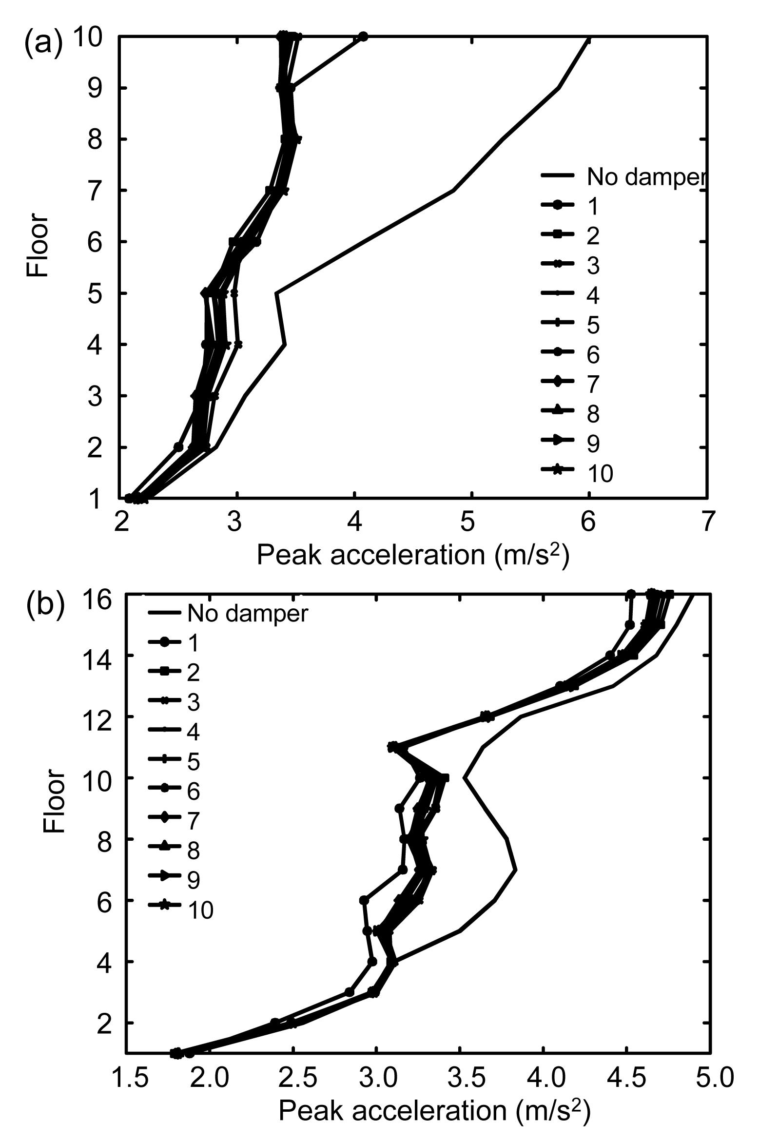
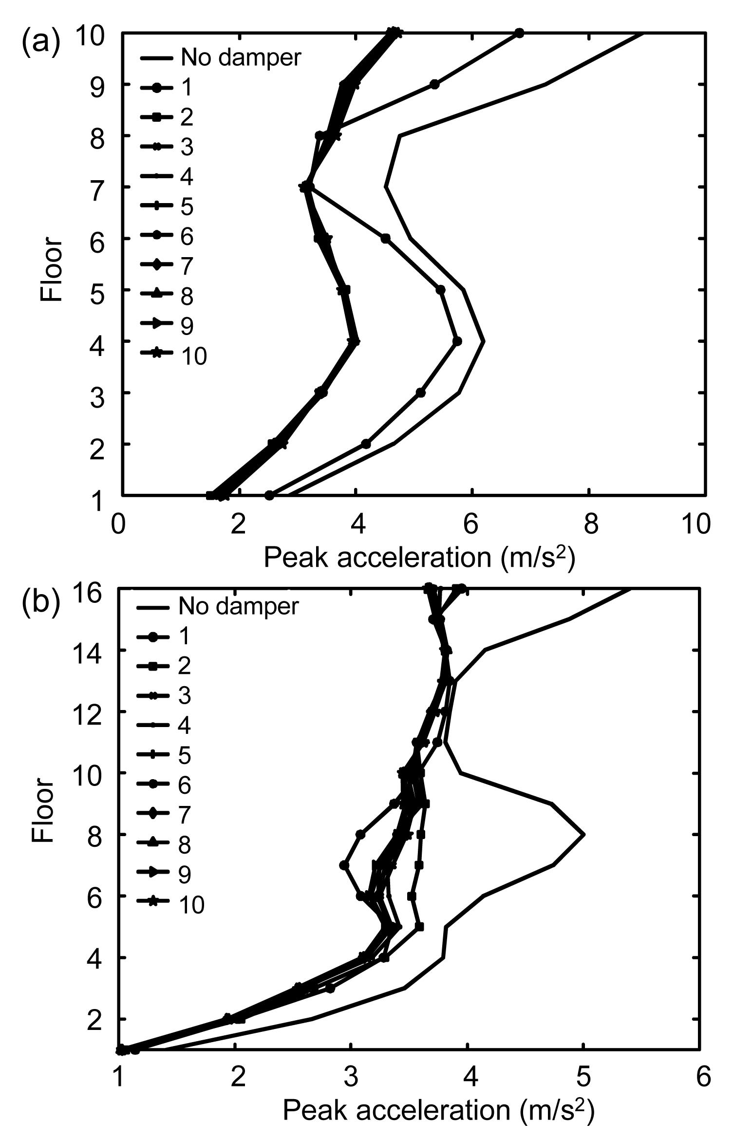
According to the results of Examples 1 and 2 in the subsection 4.3, each example has a total of ten kinds of optimal placements corresponding to different numbers of dampers, with little difference between them in their controlling effect on total vibration energy. Thus, it is necessary to study the effect of the ten kinds of optimal placements on the response reduction of the two structures. Figs. 11–22 show the peak floor displacement, peak inter-story drift, and peak floor acceleration curves of adjacent structures under the EI Centro and Taft earthquake excitation of Examples 1 and 2. The seismic responses of the two structures are mitigated significantly, and the dampers perform very well.
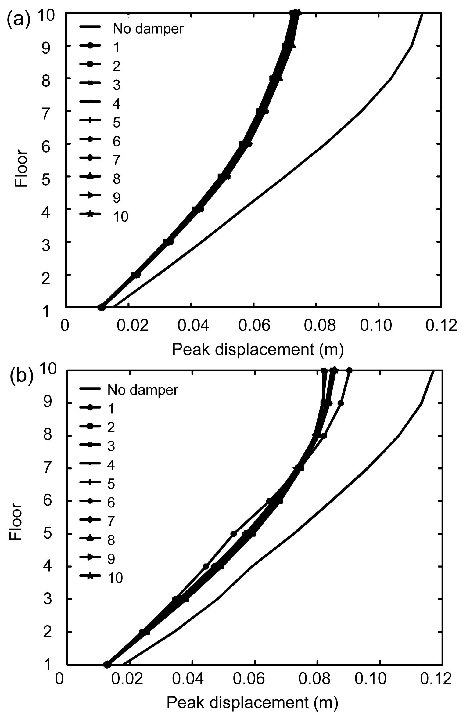
Fig.11 Peak floor displacement curves of two structures under EI Centro earthquake excitation (Example 1) (a) Structure 1; (b) Structure 2
Fig.12 Peak floor displacement curves of two structures under Taft earthquake excitation (Example 1) (a) Structure 1; (b) Structure 2
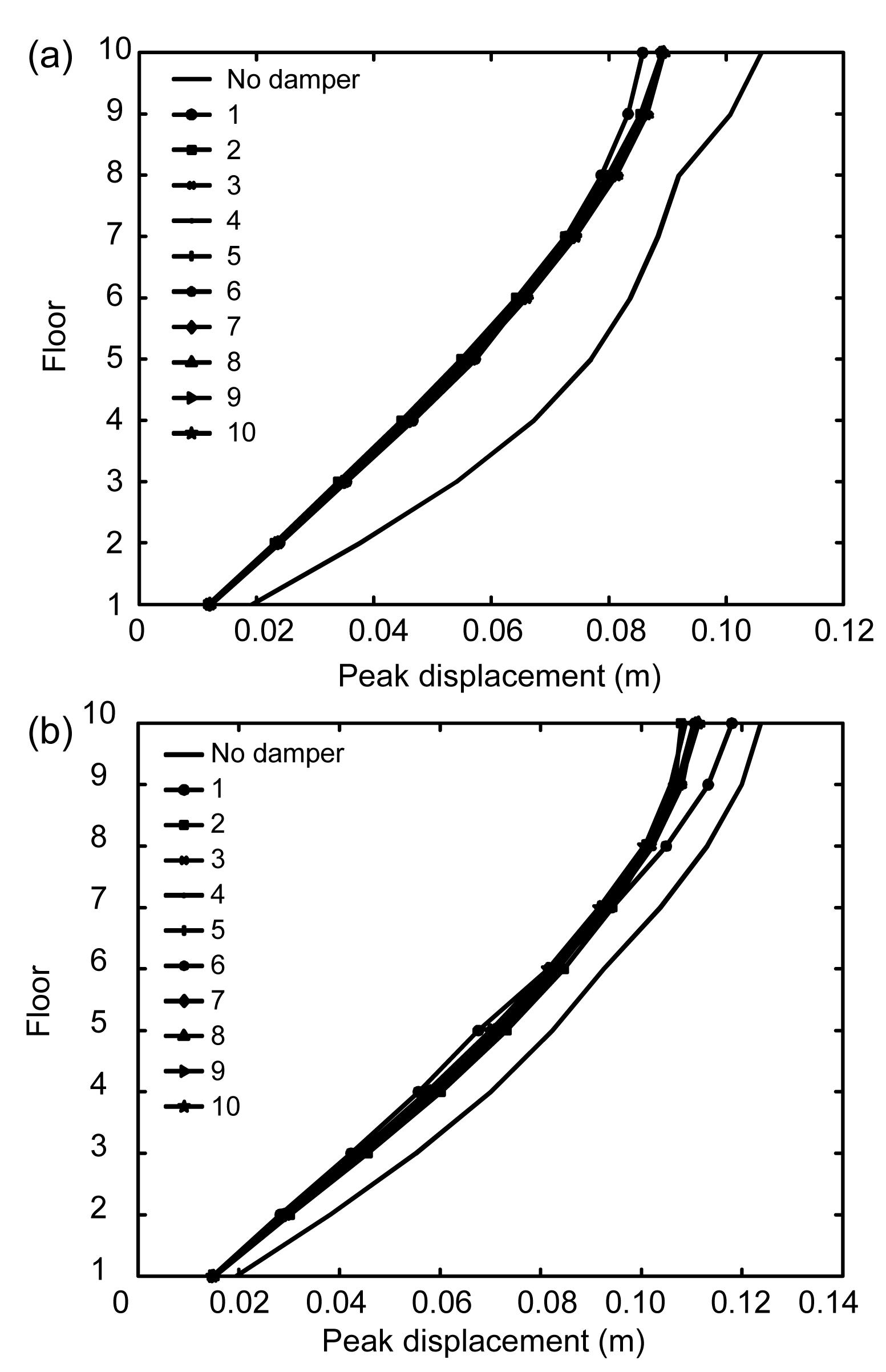
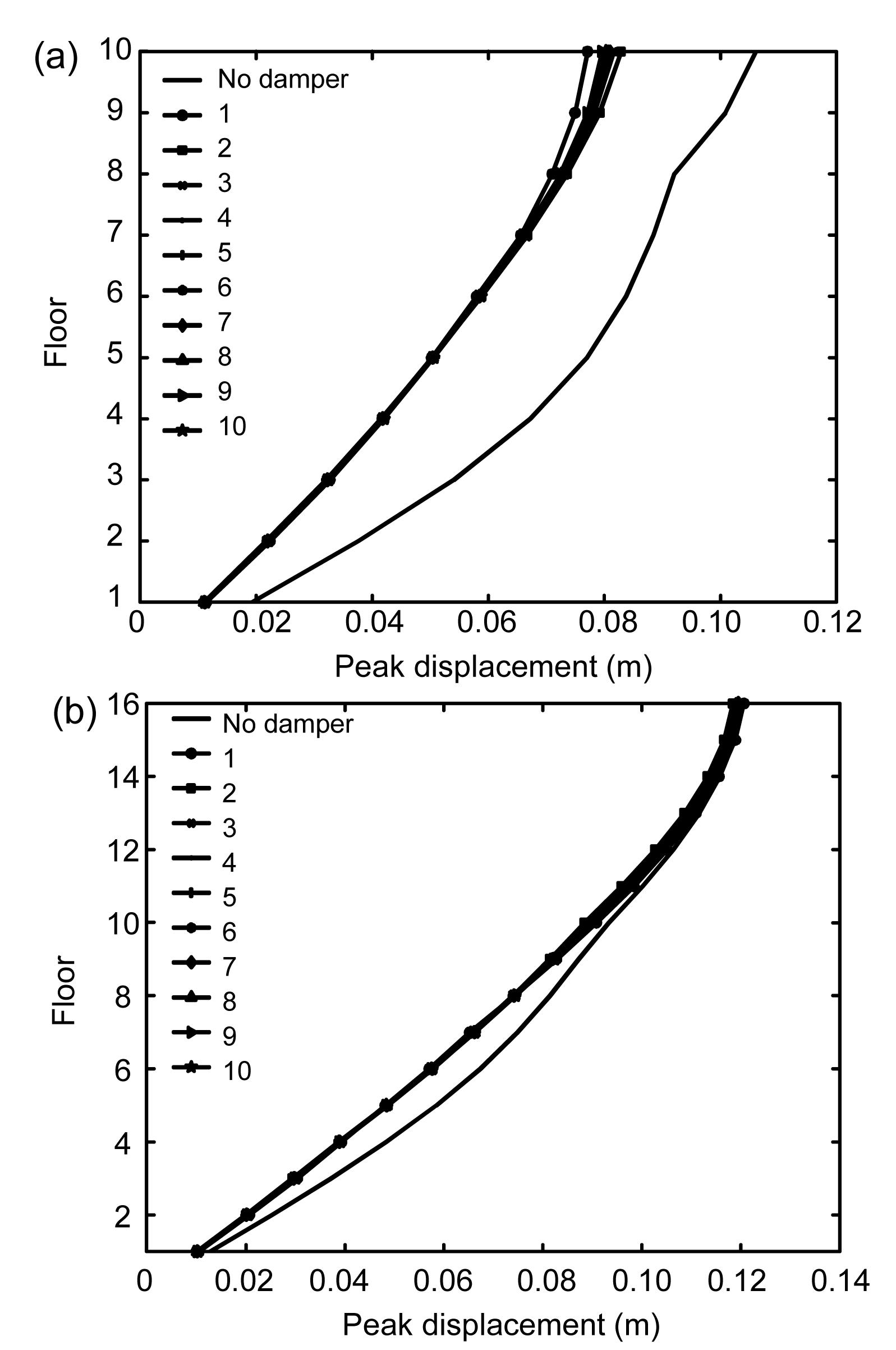
Fig.13 Peak floor displacement curves of two structures under EI Centro earthquake excitation (Example 2) (a) Structure 1; (b) Structure 2
Fig.14 Peak floor displacement curves of two structures under Taft earthquake excitation (Example 2) (a) Structure 1; (b) Structure 2
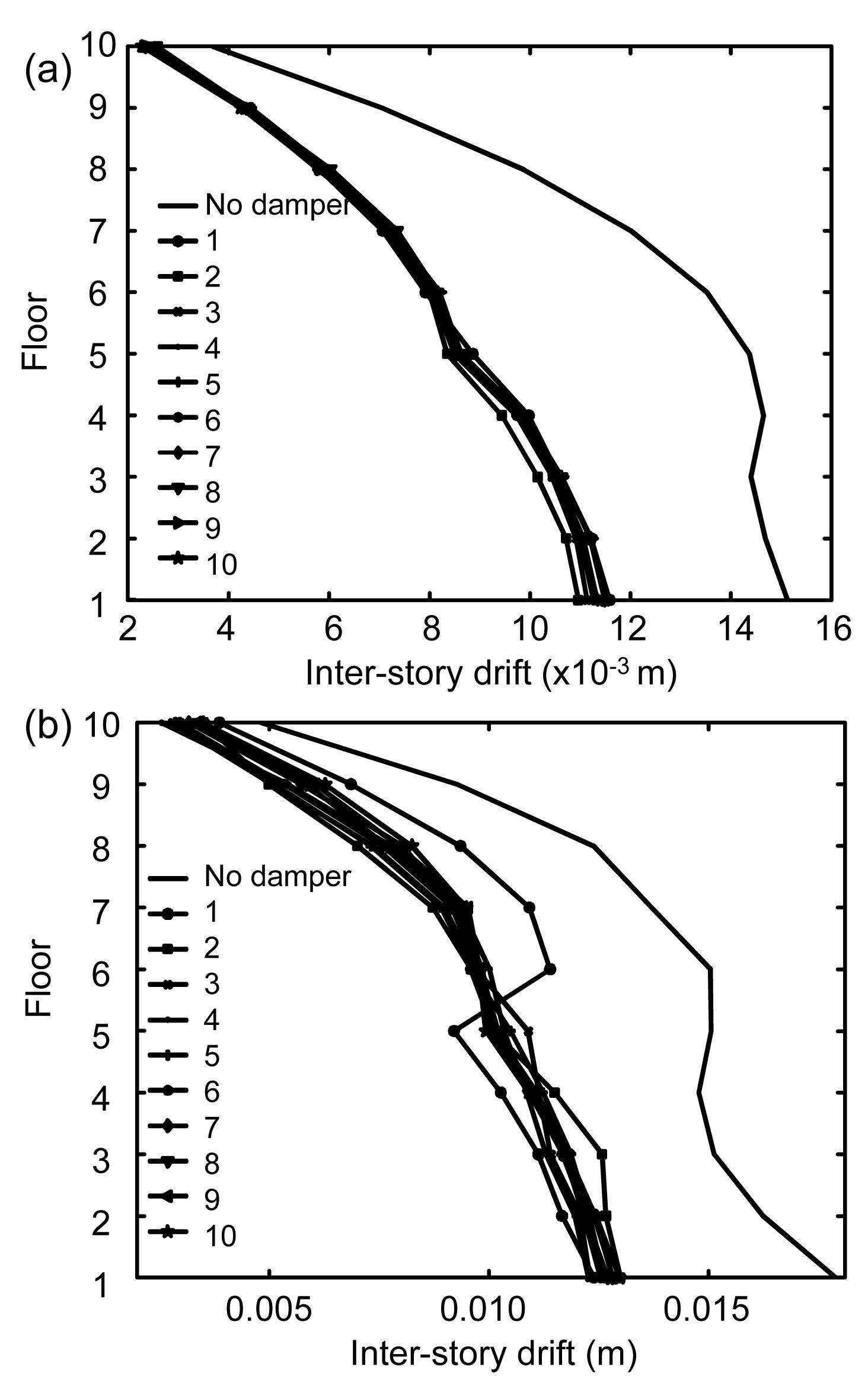
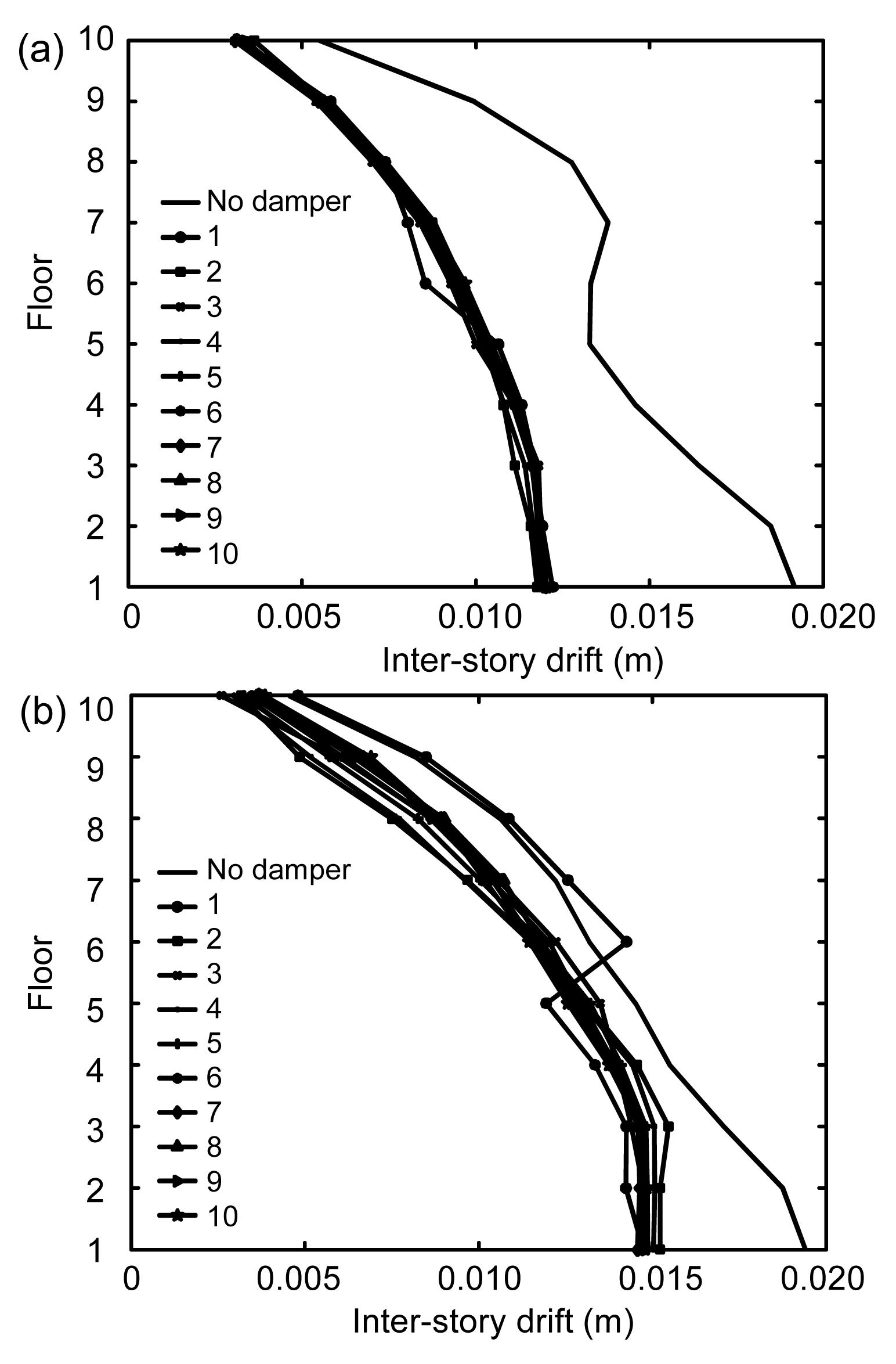
Fig.15 Peak inter-story drift curves of two structures under EI Centro earthquake excitation (Example 1) (a) Structure 1; (b) Structure 2
Fig.16 Peak inter-story drift curves of two structures under Taft earthquake excitation (Example 1) (a) Structure 1; (b) Structure 2
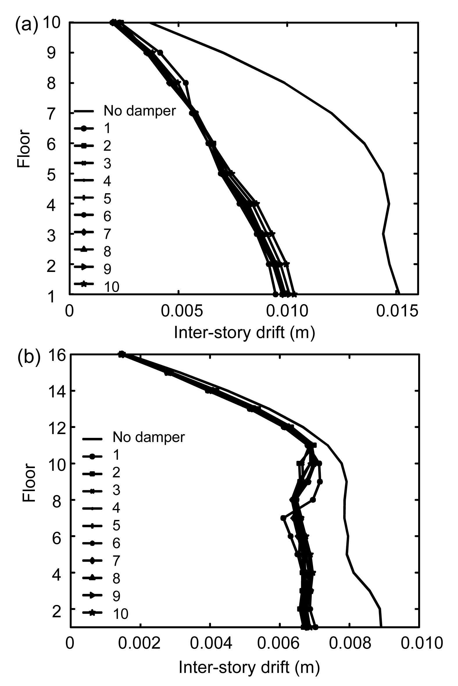
Fig.17 Peak inter-story drift curves of two structures under EI Centro earthquake excitation (Example 2) (a) Structure 1; (b) Structure 2
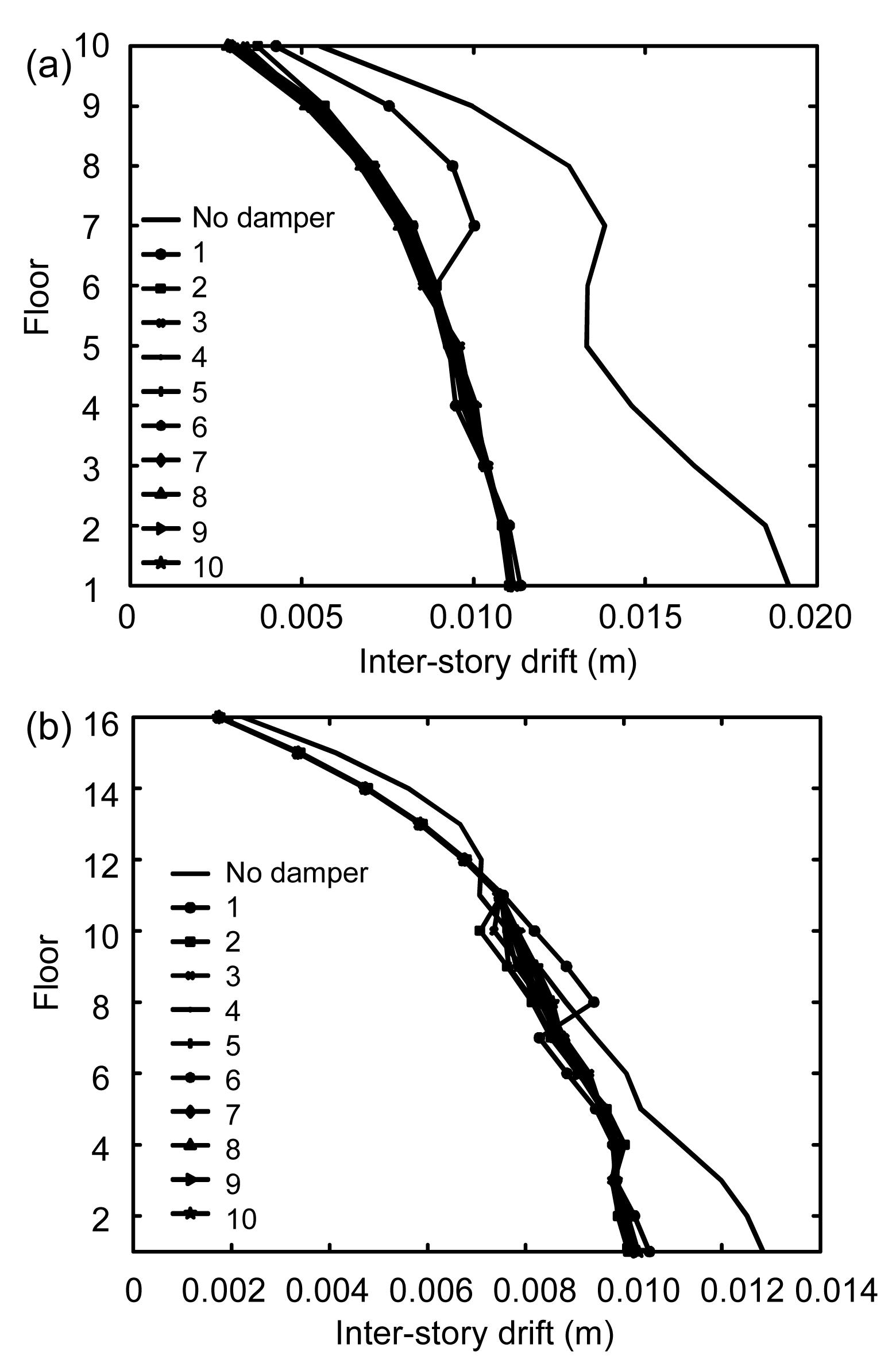
Fig.18 Peak inter-story drift curves of two structures under Taft earthquake excitation (Example 2) (a) Structure 1; (b) Structure 2
Fig.19 Peak floor acceleration curves of two structures under EI Centro earthquake excitation (Example 1) (a) Structure 1; (b) Structure 2
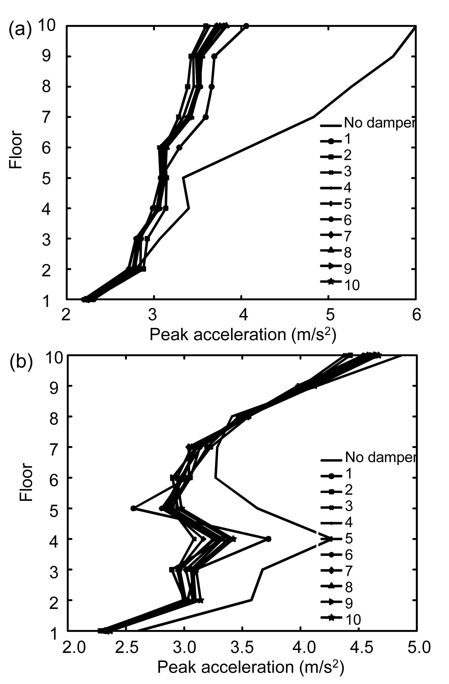
Fig.20 Peak floor acceleration curves of two structures under Taft earthquake excitation (Example 1) (a) Structure 1; (b) Structure 2
Fig.21 Peak floor acceleration curves of two structures under EI Centro earthquake excitation (Example 2) (a) Structure 1; (b) Structure 2
Fig.22 Peak floor acceleration curves of two structures under Taft earthquake excitation (Example 2) (a) Structure 1; (b) Structure 2
Figs. 11–14 show the peak floor displacement curves of adjacent structures of Examples 1 and 2. The peak floor displacement curves are nearly the same for the ten kinds of optimal placements. The change in the number of dampers has little effect on the peak floor displacement when the dampers are all placed in the optimal positions.
Figs. 15–18 show the peak inter-story drift curves of adjacent structures of Examples 1 and 2. For combination 1 when only one damper is used, there are protuberances on the peak inter-story drift curves. This is because when only one damper is used, the output force of the damper is big and centralized. In Figs. 16b and 18b, for combination 1, the peak inter-story drifts of some floors are greater than the original inter-story drifts with no damper; this situation should be avoided. For other combinations, the distribution of dampers become uniform, and the output forces of the dampers are reduced, so the peak inter-story drift curves are consistent, with few differences among them.
Figs. 19–22 show the peak floor acceleration curves of adjacent structures of Examples 1 and 2. In Fig. 19b, for combination 1, the peak floor acceleration of some floors is greater than the original acceleration with no damper. In Fig. 22a, the control of the damper in combination 1 is not as effective as in other combinations.
6. Conclusions
Optimal parameter expressions were used to calculate the optimal stiffness and damping coefficients of VEDs. The optimal arrangement of VEDs between adjacent structures under seismic excitation was then investigated. Two pairs of adjacent structures were considered: two equal-height buildings and two unequal-height buildings. The following results were obtained:
The higher is the number of the dampers, the smaller is the difference in the control effect between the optimal and the worst placements of dampers. Thus, the optimal placement of dampers is more important when fewer dampers are used.
Only one damper placed between two adjacent structures should be avoided. The output force of the damper is too big and centralized, resulting in detrimental effects on the structures.
If more than one damper is used, they should be distributed and placed on the top and lower floors of the structures; when many dampers are used, the need for placement optimization is reduced, so they can be placed according to engineering requirements.
Few differences in control performance were found in comparisons of optimization results corresponding to different numbers of dampers. Thus, optimization of the number of dampers has little effect on control performance, and optimization of the placement of a certain number of dampers is most important.
Through comparative study, for buildings of equal and unequal heights, the optimal parameters of dampers from parametric studies are consistent with theoretical results for different numbers and placements of dampers. The level of response reduction is sensitive to the value of the optimal damping coefficient of the dampers, and the linear spring of a VED has little positive effect on reducing the responses of the structures.
[1] Abdullah, M.M., Hanif, J.H., Richardson, A., Sobanjo, J., 2001. Use of a shared tuned mass damper (STMD) to reduce vibration and pounding in adjacent structures. Earthquake Engineering and Structural Dynamics, 30(8):1185-1201.
[2] Basili, M., De Angelis, M., 2007. Optimal passive control of adjacent structures interconnected with nonlinear hysteretic devices. Journal of Sound and Vibration, 301(1-2):106-125.
[4] Bhaskararao, A.V., Jangid, R.S., 2006. Seismic response of adjacent buildings connected with friction dampers. Bulletin of Earthquake Engineering, 4(1):43-64.
[5] Bhaskararao, A.V., Jangid, R.S., 2006. Seismic analysis of structures connected with friction dampers. Engineering Structures, 28(5):690-703.
[6] Bhaskararao, A.V., Jangid, R.S., 2006. Harmonic response of adjacent structures connected with a friction damper. Journal of Sound and Vibration, 292(3-5):710-725.
[7] Clough, R., Penzien, J., 2004. Dynamics of Structures (2rd Edition). Computers and Structures, Inc,Berkeley, California, USA :
[8] Ge, D.D., Zhu, H.P., Wang, D.S., Huang, M.S., 2010. Seismic response analysis of damper-connected adjacent structures with stochastic parameters. Journal of Zhejiang University SCIENCE A (Applied Physics & Engineering), 11(6):402-414.
[9] Kasai, K., Maison, B.F., 1997. Building pounding damage during the 1989 Loma Prieta earthquake. Engineering Structures, 19(3):195-207.
[10] Kim, J., Ryu, J., Chung, L., 2006. Seismic performance of structures connecting by viscoelastic dampers. Engineering Structures, 28(2):183-195.
[11] Lavan, O., Levy, R., 2006. Optimal peripheral drift control of 3D irregular framed structures using supplemental viscous dampers. Journal of Earthquake Engineering, 10(6):903-923.
[12] Ok, S.Y., Song, J., Park, K.S., 2008. Optimal design of hysteretic dampers connecting adjacent structures using multi-objective genetic algorithm and stochastic linearization method. Engineering Structures, 30(5):1240-1249.
[13] Patel, C.C., Jangid, R.S., 2011. Dynamic response of adjacent structures connected by friction damper. Earthquake and Structures, 2(2):149-169.
[14] Roh, H., Cimellaro, G.P., Garcia, D.L., 2011. Seismic response of adjacent steel structures connected by passive device. Advances in Structural Engineering, 14(3):499-517.
[15] Silvestri, S., Trombetti, T., 2007. Physical and numerical approaches for the optimal insertion of seismic viscous dampers in shear-type structures. Journal of Earthquake Engineering, 11(5):787-828.
[16] Singh, M.P., Moreschi, L.M., 2002. Optimal placement of dampers for passive response control. Earthquake Engineering and Structural Dynamics, 31(4):955-976.
[17] Takewaki, I., 2007. Earthquake input energy to two buildings connected by viscous dampers. Journal of Structural Engineering, 133(5):620-628.
[18] Trombetti, T., Silvestri, S., 2006. On the modal damping ratios of shear-type structures equipped with Rayleigh damping systems. Journal of Sound and Vibration, 292(1-2):21-58.
[19] Trombetti, T., Silvestri, S., 2007. Novel schemes for inserting seismic dampers in shear-type systems based upon the mass proportional component of the Rayleigh damping matrix. Journal of Sound and Vibration, 302(3):486-526.
[20] Xu, Y.L., He, Q., Ko, J.M., 1999. Dynamic response of damper-connected adjacent buildings under earthquake excitation. Engineering Structures, 21(2):135-148.
[21] Zhu, H.P., Iemura, H., 2000. A study of response control on the passive coupling element between two parallel structures. International Journal of Structural Engineering and Mechanics, 9(4):383-396.
[22] Zhu, H.P., Ge, D.D., Huang, X., 2011. Optimum connecting dampers to reduce the seismic responses of parallel structures. Journal of Sound and Vibration, 330(9):1931-1949.
Open peer comments: Debate/Discuss/Question/Opinion


Open peer comments: Debate/Discuss/Question/Opinion
<1>