Affiliation(s):
1.
School of Civil Engineering, Beijing Jiaotong University, Beijing 100044, China; moreAffiliation(s): 1.
School of Civil Engineering, Beijing Jiaotong University, Beijing 100044, China; 2.
Beijing MTR Construction Administration Corporation, Beijing 100037, China; 3.
Railway Engineering Group, Faculty of Civil Engineering and Geosciences, Delft University of Technology, the Netherlands; less
Ke-fei Li, Wei-ning Liu, Valeri Markine, Zhi-wei Han. Analytical study on the dynamic displacement response of a curved track subjected to moving loads[J]. Journal of Zhejiang University Science A, 2013, 14(12): 867-879.
@article{title="Analytical study on the dynamic displacement response of a curved track subjected to moving loads", author="Ke-fei Li, Wei-ning Liu, Valeri Markine, Zhi-wei Han", journal="Journal of Zhejiang University Science A", volume="14", number="12", pages="867-879", year="2013", publisher="Zhejiang University Press & Springer", doi="10.1631/jzus.A1300225" }
%0 Journal Article %T Analytical study on the dynamic displacement response of a curved track subjected to moving loads %A Ke-fei Li %A Wei-ning Liu %A Valeri Markine %A Zhi-wei Han %J Journal of Zhejiang University SCIENCE A %V 14 %N 12 %P 867-879 %@ 1673-565X %D 2013 %I Zhejiang University Press & Springer %DOI 10.1631/jzus.A1300225
TY - JOUR T1 - Analytical study on the dynamic displacement response of a curved track subjected to moving loads A1 - Ke-fei Li A1 - Wei-ning Liu A1 - Valeri Markine A1 - Zhi-wei Han J0 - Journal of Zhejiang University Science A VL - 14 IS - 12 SP - 867 EP - 879 %@ 1673-565X Y1 - 2013 PB - Zhejiang University Press & Springer ER - DOI - 10.1631/jzus.A1300225
Abstract: A closed-form out-of-plane dynamic displacement response of a curved track subjected to moving loads was proposed. The track structure was modeled as a planar curved Timoshenko beam periodically supported by the double-layer spring-damping elements. The general dynamic displacement response induced by the moving loads along the curve on the elastic semi-infinite space was firstly obtained in the frequency domain, according to the Duhamel integral and the dynamic reciprocity theorem. In the case of the periodic curved track structure subjected to moving loads, the dynamic displacement equation was simplified into a form of summation within the basic track cell instead of the integral. The transfer function for the curved track was expressed in the form of a transfer matrix. Single and series moving loads were involved in the calculation program. For the verification of the analytical model, the mid-span vertical deflection of a simply support curved beam subjected to moving load was recalculated and compared with the same case in the reference. The research results indicate that: under the same moving loads, the displacement response of the curved track decreases slightly with the increasing track radius, and the displacement response of the curved track with the radius greater than or equal to 600 m is almost equivalent to the displacement response of the straight track; the frequency spectrum of the curved track is more abundant than that of the straight track, which may result in more wheel-rail resonance and rail corrugation in the curved lines.
Darkslateblue:Affiliate; Royal Blue:Author; Turquoise:Article
Article Content
1. Introduction
Planar curved beams, arches and rings have been widely used in machines and structures, such as the track structures, bridges, aircraft structures, and turbo machinery blades, because of their potential applications. A curved track can meet the requirements of the existing urban layout well in the urban rail transit system; however, the vibration of the curved track can not be ignored.
The vibration theory of the uniform curved beams has great importance in many engineering applications, while the in-plane vibration and out-of-plane vibration were usually studied separately. The “out-of-plane” here refers to “normal to the plane” of the curvature of the curved beam. The curved track structure was modeled as a planar curved Timoshenko beam periodically supported by the double-layer spring-damping elements to study the vibration of the curved track here, and only the out-of-plane vibration of the curved track structure was considered.
Both the analytical methods and the finite element method have been employed in the pioneering study on the out-of-plane vibration of the curved beam; however, the analytical methods were more popular in use. For the finite element method, the complex formulations for the existing element property matrices of the curved beam element discourage the engineers from employing it to analyze either in-plane or out-of-plane vibration of the curved beams.
For this analytical study, the out-of-plane vibration equations of the curved beams and an analytical solution for a circular ring were firstly derived by Love (1927). Then, Den Hartog (1928) obtained the natural frequencies of circular arcs with fixed and hinged boundary conditions using the Rayleigh-Ritz method. Volterra and Morell (1961) obtained the lowest natural frequency of elastic arc for vibrations outside the plane of initial curvature. However, the theory above gave wrong results for the higher mode frequencies, since earlier analytical studies were based on the classical beam theory with the effects of shear deformation and/or rotary inertias neglected.
It was not until the 1970s that Rao (1971) presented more accurate models to derive the natural frequencies of the circular rings and arcs, in which the effects of shear deformation and rotary inertias were both taken into account. Using a transfer matrix approach, Bickford and Strom (1975) obtained the natural frequencies and mode shapes for both the in-plane and out-of-plane vibrations of plane curved beams accounting for shear deformation, rotary inertia and extension of the neutral axis. Then, it was found that the accuracy of the results may be improved if the effect of variation in curvature across the cross-section of the thick curved beam was considered (Bickford and Maganty, 1986). Then, Montalvão e Silva and Urgueira (1988) derived the dynamic stiffness matrices for the out-of-plane vibration of the curved beams to get the natural frequencies. The frequency equations for the multi-span circular curved beam were derived, with the circumferential forces in the curved beam being neglected (Wang et al., 1980). Afterwards, more complicated formulations were derived by applying the discrete Green functions and using the numerical integration to obtain the eigenvalues for both the in-plane and out-of-plane free vibrations of the non-uniform curved beams (Kawakami et al., 1995). The wave propagation approach was also very useful in vibration analysis, in which the vibration of elastic structures such as strings, beams, and plates can be described in terms of waves propagating and attenuating in waveguides (Yong and Lin, 1989). Considering the curved bridge coupling of bending and torsion in the vertical direction, as well as the bending and axial deformation in the horizontal direction, the precise transfer matrixes of the curved beam were derived in vertical and horizontal directions to calculate the horizontal and vertical vibration frequencies and vibration modes (Sun et al., 2009).
Few works have been conducted for the vibration response of the curved beams under moving loads and concern was mainly placed on the vertical or out-of-plane vibration of the curved bridges under moving loads (Tan and Shore, 1968; Genin et al., 1982; Sun and Li, 2009). Yang et al. (2001) derived the analytical solutions for a horizontally curved beam subjected to vertical loads due to the gravities of the vehicles and horizontal loads due to the centrifugal forces of the vehicles moving along a circular path; however, they neglected the effect of shear deformation and considered only the first mode approximations for the vertical defection and torsional angle in the forced vibration analysis.
The problem of a moving load was reviewed in detail in (Timošenko, 1953), where its coming-into-being can be traced to the beginning of the nineteenth century, the time of erection of the early railway bridges (Stokes, 1849), which makes it one of the original problems of structural dynamics in general. The vibration response of the track structure under moving loads has also been paid much attention. Initially, the track was modeled as a continuous supported Euler beam on the elastic foundation, ignoring the periodic sleeper. The model was then improved as the Timoshenko beam with higher modes; the contribution of the shear stress was taken into account (Zhai, 2002). In the case where the track is invariant in the longitudinal direction, the dynamic solution can be efficiently obtained in the frequency-wave number domain (Degrande and Lombaert, 2001; Ding et al., 2010). A dynamic analytical model was established on the periodically supported track structure subjected to the moving loads (Liu and Zhang, 2004; Zhang, 2004). However, the straight track structure was only considered.
An analytical solution on the dynamic displacement response of the curved track subjected to moving loads was proposed in this study, in which the track structure was modeled as a planar curved Timoshenko beam periodically supported by the double-layer spring-damping elements. The general dynamic displacement response induced by the moving loads along the curve on the elastic semi-infinite space was firstly obtained, according to the Duhamel integral and the Dynamic Reciprocity Theorem. In the case of a periodic curved track structure subjected to moving loads, the dynamic displacement response equation in the frequency domain was simplified into a form of summation within the basic track cell instead of the integral. The transfer function for the curved track was expressed in the form of a transfer matrix. Various kinds of moving loads were involved in the calculation program. The midpoint vertical deflection of a simply support curved beam subjected to single moving load was recalculated and compared with the same case in (Yang et al., 2001) to verify the correctness of the analytical model. Then the dynamic displacement response of the curved track with different radius was studied.
2. Semi-infinite space subjected to a single moving load
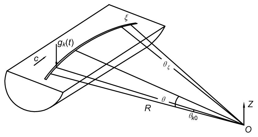
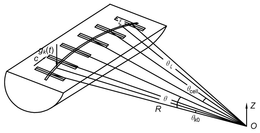
Firstly, let us consider the vertical load gk(t) (Fig. 1), moving along the curve on an elastic semi-infinite space. The vertical dynamic displacement response of the point ξ can be expressed by
,
where u(ξ, t) represents the vertical displacement of the point ξ; hz(θξ, θ(τ), t−τ) represents the vertical transfer function between the load point θ(τ) and the point ξ, and when t−τ<0, hz(θξ, θ(τ), t−τ)≡0.
Fig.1 Semi-infinite space subjected to a single moving load along the curve
As shown in Fig. 1, the load gk(t) moves along the curve with the radius of R, θk0 is the initial position of the moving load, and c is the moving speed, then Eq. (1) can be rewritten as
.
According to the dynamic reciprocal theorem and the theory of the forward Fourier transformation, the frequency-domain displacement response can be expressed by ,
where represents the transfer function in the frequency domain; ω represents the circular frequency; “^” is defined to be the expression in the frequency domain, similarly hereinafter.
So far, the time-domain and frequency-domain dynamic displacement responses of the point ξ on the elastic semi-infinite space subjected to the vertical moving load along the curve are obtained.
3. Track structure subjected to a single moving load
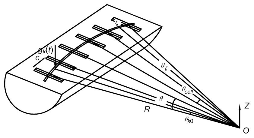
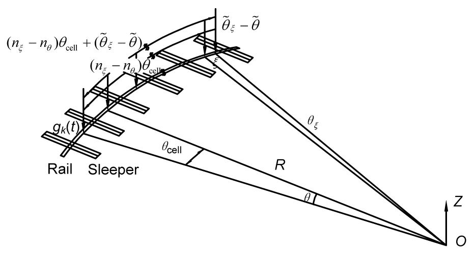
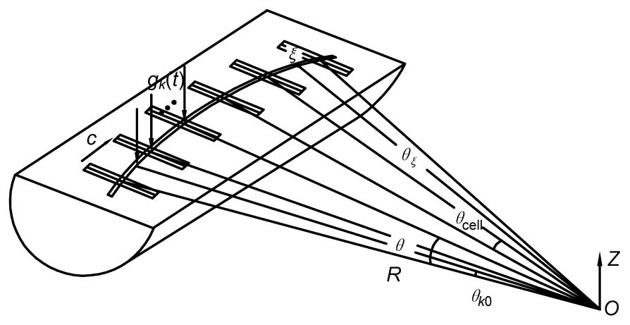
The dynamic displacement response of the periodically supported track structure subjected to a single moving load is considered. As shown in Fig. 2, half of the track structure is only taken into account. The track structure is subdivided into a certain amount of basic track cells, with the support spacing of θcell.
Fig.2 Periodically supported curved track subjected to a single moving load
The vertical load gk(t) moves along the rail, c is the moving speed, θk0 is the initial position of the load. ξ is the point on the rail. The load point θ can be expressed by .
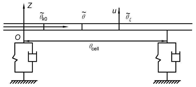
As shown in Fig. 3, the local coordinate system is set up in a basic track cell. The relationship between the global coordinate system and the local coordinate system can be defined as
,
,
,
where “˜” is defined to be the expression in the local coordinate system, similarly hereinafter; nθ represents the quantity of the track cells between the origin O and the load point θ in the global coordinate; nξ represents the quantity of the track cells between the origin O and the point ξ in the global coordinate; and nk0 represents the quantity of the track cells between the origin O and the initial position θk0 of the load in the global coordinate. Then, we have
,
.
Fig.3 Local coordinate system set up in a basic track cell
As the load moving in a basic track cell, the frequency-domain dynamic displacement response in Eq. (3) can be simplified into a form of summation within the basic track cell instead of the integral.
As the load moving along the curved track, the displacement response of the point ξ can be expressed by
where nθ increases with the load moving along the rail, and θt is the overall length of the curved track.
Taking Eq. (9) into Eq. (11), then we can obtain:
,
which represents the frequency-domain dynamic displacement response of the track structure subjected to a single moving load.
4. Track structure subjected to a series of moving loads
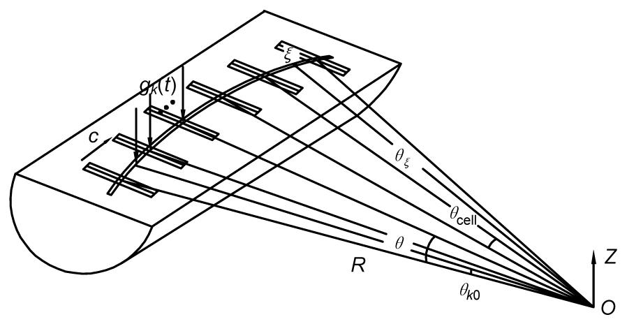
Now, the periodically supported curved track structure subjected to a series of moving loads is considered. As shown in Fig. 4, the m-axle loads gk(t) (k=1, 2, …, m), with time-dependent amplitudes, move along the rail, and the initial position coordinate of the moving loads is (ρk0, θk0, zk0) (k=1, 2, …, m), the moving speed is c.
Fig.4 Periodically supported track structure subjected to a series of moving loads along the curve
The position of the kth load gk(t) can be expressed by [ρ, θ, z]T=[ρk0, θk0+ct, zk0]T, and (ρk0, θk0, zk0) is the initial position of the load gk(t).
The series of moving loads along the rail can be expressed by
.
According to the forward Fourier transformation, we can obtain:
.
Substituting Eq. (15) into Eq. (12), then
where nk0 represents the quantity of the track cells between the origin O and the load point yk0 in the global coordinate, k=1, 2, …, m.
For the periodically supported track structure (Fig. 4), , we can always take the form as
,
where θk is the distance between kth axle and the first axle.
Eq. (17) represents the frequency-domain vertical dynamic displacement response of the curved track subjected to a series of moving loads. Then, the transfer function for the curved track system will be expressed in the form of the transfer matrix in the following sections.
5. Transfer function for a curved track structure
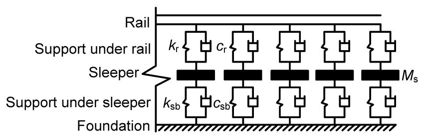
As shown in Fig. 5, the curved track is simulated as a periodically supported planar curved Timoshenko beam. The periodic support is modeled as the double-layer spring-damping element, in which the rail pad and the sleeper pad are both modeled as the spring-damping elements; the sleeper is modeled as the concentrate mass. In Fig. 5, kr, ksb are the stiffness of the support under rail and sleeper, respectively; cr, csb are the damping of the support under rail and sleeper, respectively, and Ms is the sleeper mass.
Fig.5 Simulated model of the periodically supported track structure
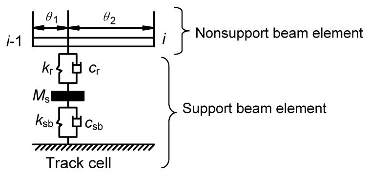
The curved track cell can be decomposed into the nonsupport curved beam elements and the support elements, as shown in Fig. 6.
Fig.6 Nonsupport beam elements and support element of the track cell
Combining the transfer matrices for the nonsupport beam elements Tbeam and the transfer matrix for the support elements Tsupport, the transfer matrix for the curved track cell Tcell can be expressed by
,
where θcell=θ1+θ2.
The state variables of the point are defined as S(ω)=[Qz, My, Mx, Bi, u, α, φ, γ]T, and then the state variables of the point i−1 and the point i will be:
,
where Si(ω) and Si−1(ω) are the state variables of the point i and the point i−1, respectively.
is defined to be the transfer function for the state variables S(θ, ω). Then, the transfer function can be solved as the product of the state variables S(θ, ω) of the load point θ and the transfer matrix for the track between the load point θ and the point ξ, which is given by
.
The transfer function , for the vertical displacement u, in Eq. (17), is just one of the elements of the transfer function for the state variables S(θ, ω), as shown in Eq. (20).
As shown in Fig. 7, the track between the load point θ and the point ξ can be divided into curved track cells and curved beam, and then the transfer matrix can be expressed by
,
where is the transfer matrix for the track cell θcell, and is the transfer matrix for the curved beam
.
Fig.7 Track structure between the load point θ and the point ξ
The transfer matrix for the curved beam element Tbeam and the transfer matrix for the support element Tsupport will be studied in the following sections.
5.1. Transfer matrix for the curved beam element
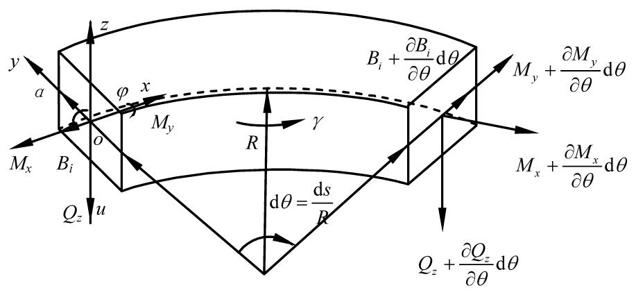
As shown in Fig. 8, the length of the curved beam along the neutral axis is denoted by s, and the x-, y-, and z-axes are taken in tangential directions, radial, and transverse directions, respectively. The origin of the coordinates moves along the neutral axis of the curved beam. u is the transverse deflection, α is the slope due to the pure bending, φ is the angle of torsion, γ is the warping angle, R is the radius, and θ is the central angle corresponding to the curved element. The cross-section properties and material properties are constant along the beam. The shearing force Qz, the bending moment My, the torsional moment Mx, and the double warping moment Bi are all shown in Fig. 8.
Fig.8 Analysis coordinates of the curved beam element
For the infinitesimal curved beam element ds, the shear deformation is taken into account, then we can obtain:
,
where ν is the transverse shear angle.
The vertical deflection rate Ky of the beam element is defined by
.
The distortion rate Kx of the beam element is defined by
.
The warping angle γ can be expressed by
.
The force-displacement relationship of the curved beam can be expressed by
,
,
,
,
where E is the Young’s modulus, G is the shear modulus, K is the shear correction factor, Iy is the vertical bending moment of inertia, Id is the free torsion moment of inertia, Is is the polar moment of the cross-section, and A is the sectional area.
According to the equilibrium condition, the out-of-plane vibration equations of the infinitesimal curved beam element can be expressed by
,
,
,
,
where ρ is the density of the curved beam.
The state variables of the point on the curved beam can be expressed by
.
The general solution for Eq. (35) can be expressed as
,
where S0 is the constant matrix.
The curved beam can be divided into many infinitesimal elements, with the length of Δx, then we can obtain:
,
,
then ,
where Tbeam(Δx)=eA1Δx, S(xl+1) and S(xl) are the state variables of the point xl+1 and the point xl, respectively.
Based on the precise integration method of the exponential matrix (Sun and Li, 2009):
,
where β=Δx/2N, N=20.
In order to avoid the loss of the accuracy during the rounding operation in the precise integration method, the exponential matrix is calculated in two steps.
Firstly, the exponential matrix is expanded to the Taylor series:
,
,
where L is the truncation order, and generally L=2, that is T0=A1β+(A1β)2/2!.
Then, Tbeam(Δx) can be expressed by
,
.
Tj (j=1, 2, …, N) can be expressed by
.
Finally,
.
Then, the transfer matrix of the curved beam element Tbeam can be settled.
5.2. Transfer matrix for the support element
As shown in Fig. 9, let us consider the support element, of which the state variables are defined as
For the left hand side: ;
For the right hand side: .
Then we can obtain:
where kv(ω) is the composite stiffness of the double-layer support element, which can be expressed by
,
where ,
cks=ks+iωcs, ckb=kb+iωcb, ckr=kr+iωcr. kr, ks, and kb are the stiffness of the rail pad, the sleeper pad, and the subgrade, respectively; cr, cs, and cb are the damping of the rail pad, the sleeper pad and the subgrade, respectively.
5.3. Initial state variables of the curved track structure
Based on the transfer matrix for the curved track structure obtained above, the initial state variables of the curved track structure will be expressed in two different cases: the moving load applied on the curved beam between two support elements and the moving load applied on the support element.
1. The load applied on the curved beam between two support elements
The state variables of the curved beam element are defined to be SL for the left side and SR for the right side, as shown in Fig. 10.
Fig.10 Mechanical analysis of the curved beam element
According to the transfer matrix, one can obtain:
.
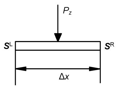
When the load Pz is applied on the curved beam between the two support elements, it is reasonable to assume that the transverse deflection u, the slope α, the angle of torsion φ, the warping angle γ, the bending moment My, the torsional moment Mx, and the double warping moment Bi are the same at this position from the left side to the right side. The summation share force of the beam on the left side and right side is equal to the applied load Pz, which can be expressed by
.
Substituting Eq. (50) into Eq. (51), the initial state variables of both sides of the curved beam elements can be settled.
2. The load applied on the support element
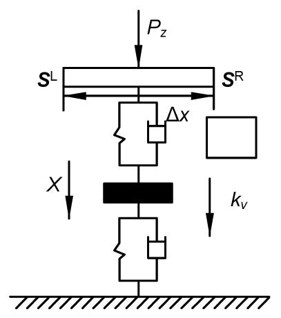
The state variables of the double sides of the support element are defined to be SL for the left side and SR for the right side.
When the load Pz is applied on the support element, as shown in Fig. 11, the displacement of the support is X, then
.
Fig.11 Mechanical analysis of the support element
According to the transfer matrix, we can obtain:
.
Substituting Eq. (54) into Eq. (53), the initial state variables of both sides of the support element can be expressed.
With the initial state variables and the transfer function for the curved track expressed above, the dynamic displacement of the curved track subjected to the moving loads can be obtained.
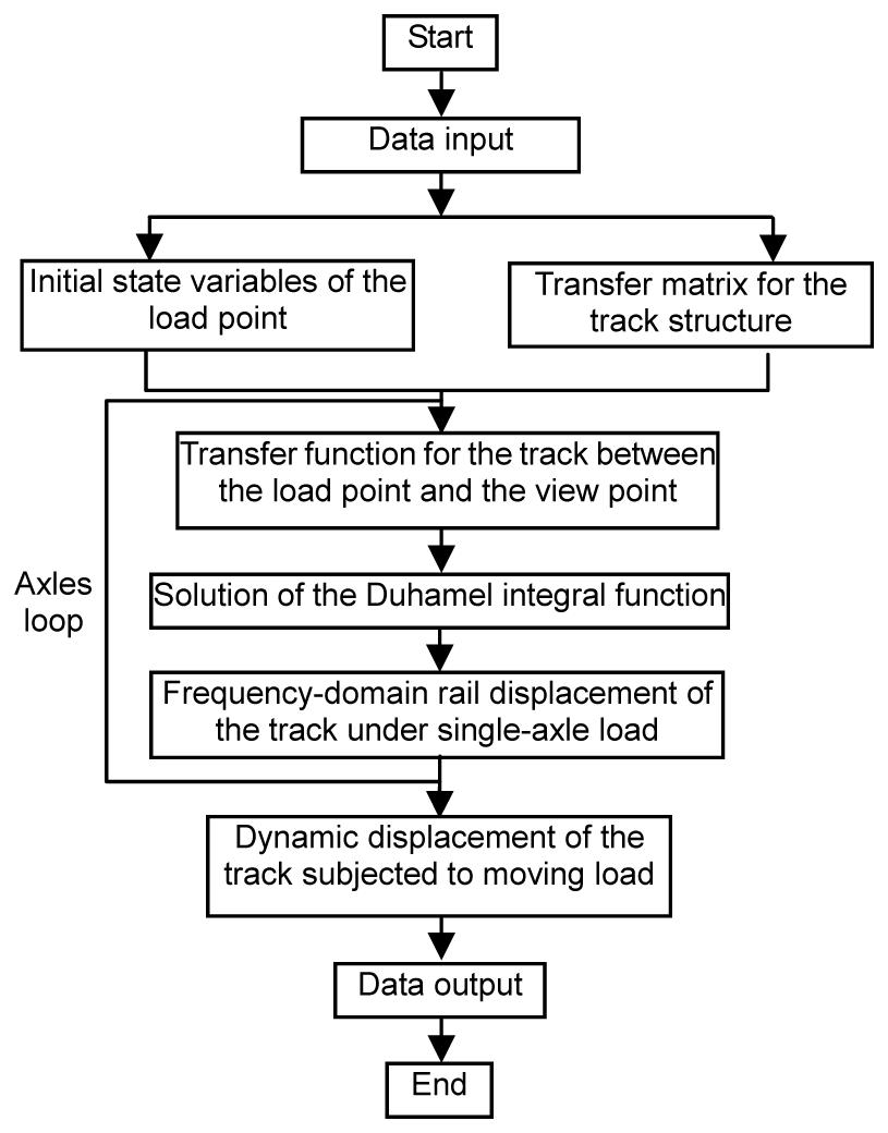
6. Calculation results
Based on the analytical model obtained in the previous sections, the numerical computations were performed to illustrate the dynamic displacement response of the curved track subjected to moving loads, using the calculation program formed with Matlab. The calculation process is shown in Fig. 12.
Fig.12 Calculation process
6.1. Model validation
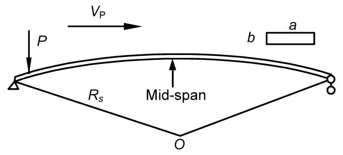
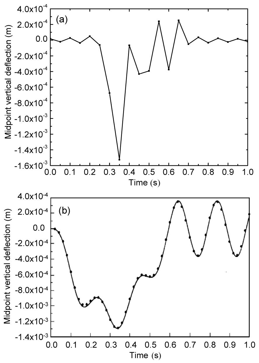
To verify the validity of the analytical model above, the midpoint vertical deflection of a simply support curved beam subjected to a single moving load was recalculated and compared with the same case in (Yang et al., 2001), as shown in Fig. 13.
Fig.13 Simply support curved beam subjected to a single moving load
According to (Yang et al., 2001), the calculation parameters of a simply support curved beam are as follows: a=5 m, b=1.8 m, ϕ=30°, Rs=45.84 m, the total length of the curved beam L=Rϕ=24 m, E=3.23×10¹⁰ N/m2, ν=0.2, G=E/[2(1+ν)], k'=0.833, Ix=ab3/12=2.43 m4, Iy=ba3/12=18.75 m4, Jθ=Ix+Iy=21.18 m4, A=ab=9 m2, Vp=40 m/s, P=9.8×29.9×103 N, and damping ζd=0.
As shown in Fig. 14, the midpoint vertical deflection was calculated and compared with the results in (Yang et al., 2001). It should be pointed out that the negative displacement means that the bottom of the beam is suffering with tension stresses. The results are consistent with that in (Yang et al., 2001), which indicates the correctness of the analytical model presented in this study.
Fig.14 Midpoint vertical deflection of a simply support curved beam subjected to a single moving load (a) Calculated results; (b) Results in (Yang et al., 2001)
6.2. Dynamic displacement response of the curved track
The vertical dynamic displacement response of the curved track subjected to single moving load is considered as shown in Fig. 15.
Fig.15 Curved track subjected to a single moving load
The single load gk(t)=1 N, with a constant speed of c=30 km/h, moves along the rail with a radius of R=300 m. The point ξ is located at 9.3 m away from the initial point of the moving load. For comparison, the vibration response of the straight track subjected to the same moving load was also obtained, according to (Liu and Zhang, 2004; Zhang, 2004).
The parameters of the track structure in the calculation are as follows: rail mass per unit length mr=60 kg/m, elastic modulus E=2.10×10¹¹ Pa, cross section area A=7.60×10⁻³ m2, cross section inertia moments I=3.04×10⁻⁵ m4, damping ratio ξr=0.01, sleeper mass per unit length ms=50 kg/m, sleeper spacing Lcell=0.60 m, bed mass per unit length mb=260 kg/m, and the mass of the sleeper and bed are taken into account together. The fastener employed here is DTVI2 fastener, of which the stiffness and damping parameters are kr=4.0×10⁷ N/m, cr=5.0×10⁴ N·s/m, respectively. The stiffness and damping parameters of the spring-damper element under the sleeper are ksb=1.0×10⁸ N/m, csb=5.0×10⁴ N·s/m, respectively.
As shown in Fig. 16, the vibration displacement, velocity, and acceleration of the point ξ on the curved track and the straight track are obtained. In order to save the computing time, the vibration in 0–50 Hz is only taken into account. According to the comparison of the time history and frequency spectrum, we can find that:
Under the same moving loads, the vibration response of the curved track is larger than that of the straight track.
The frequencies of the peak values in the frequency spectrum are around 14 Hz, 28 Hz, and 42 Hz, which are closely related to the speed of the moving load; besides, the frequency spectrum of the curved track is more abundant than that of the straight track, which may result in more wheel-rail resonance and rail corrugation in the curved lines.
Fig.16 Vibration response of the curved track subjected to a single moving load (a) Vibration displacement time history; (b) Vibration displacement frequency spectrum; (c) Vibration velocity time history; (d) Vibration velocity frequency spectrum; (e) Vibration acceleration time history; (f) Vibration acceleration frequency spectrum
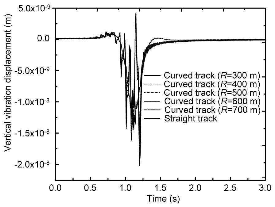
Then, the vertical dynamic displacement of the curved track with different radiuses (R=300 m, 400 m, 500 m, 600 m, 700 m) subjected to a single moving load is obtained and compared, as shown in Fig. 17.
Fig.17 Displacement responses of the straight track and curved track with different radiuses
The comparison in Fig. 17 indicates that: under the same moving load, the displacement response of the curved track decreases slightly with the increasing track radius, and the displacement response of the curved track with the radiuses greater than or equal to 600 m is almost equivalent to the response of the straight track.
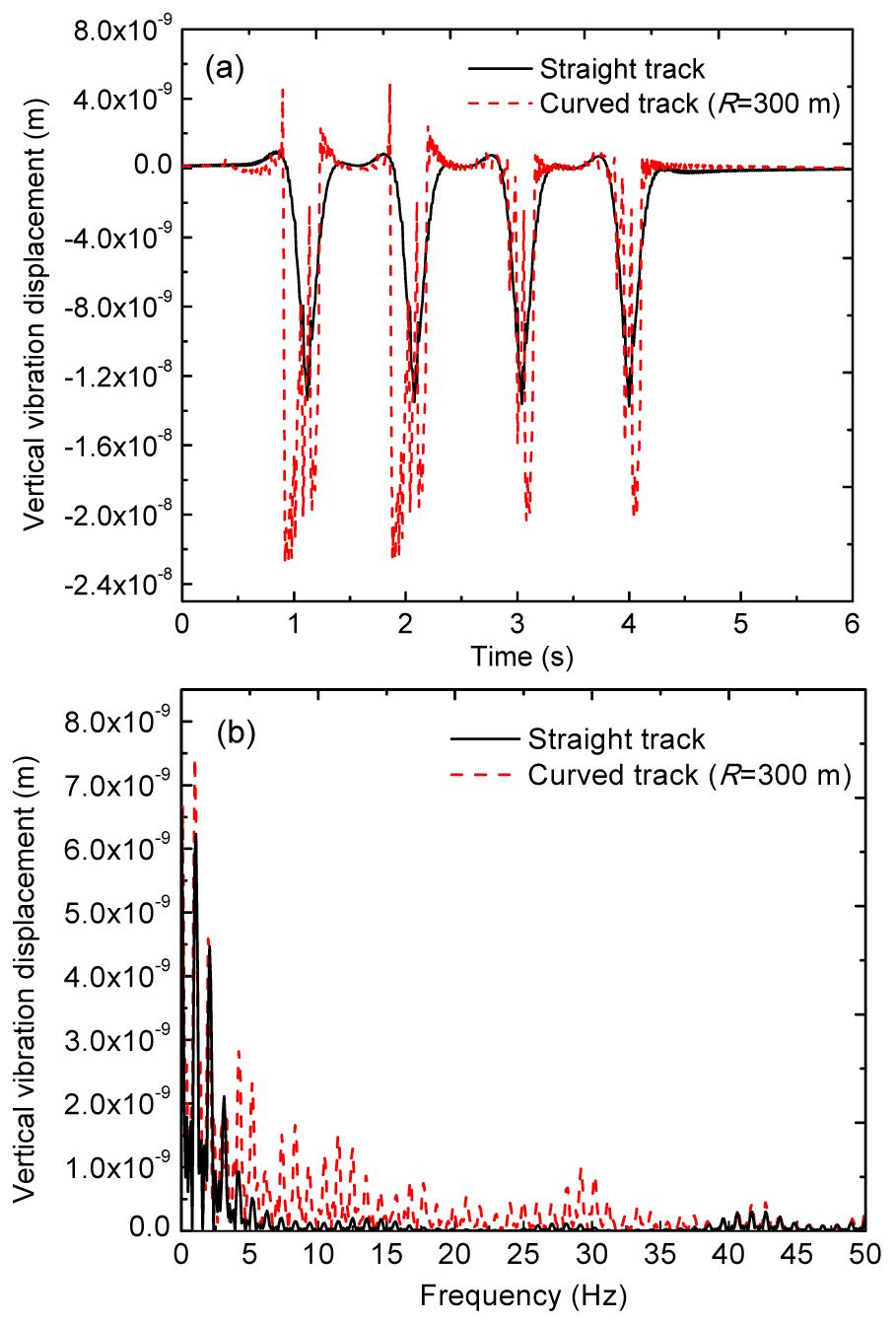
As shown in Fig. 18, the curved track subjected to a series moving loads gk(t)=1 N (k=1, 2, 3, 4), with a constant speed of c=30 km/h, is also considered. The radius of the curvature R=300 m, the distance between two adjacent loads is 8 m, and the vibration receiver ξ is located at 9.3 m away from the initial point of the first moving load.
Fig.18 Curved track subjected to a series of moving loads
The vertical dynamic displacement responses of the curved and straight track are obtained according to the calculation program. The time history and the frequency spectrum are both included. In order to save the computing time, the vibration in 0–50 Hz is only taken into account.
As shown in Fig. 19, the comparison of the time history and frequency spectrum indicates that: under the same moving loads, the vibration response of the curved track is larger than that of the straight track; the spectrum of the curved track is more abundant than that of the straight track, which may result in more wheel-rail resonance and rail corrugation in the curved lines.
Fig.19 Vibration displacement of the curved track subjected to a series of moving loads (a) Vibration displacement time history; (b) Vibration displacement frequency spectrum
7. Conclusions
A closed-form out-of-plane dynamic displacement response of the curved track subjected to moving loads was proposed. The track structure was modeled as a planar curved Timoshenko beam periodically supported by the double-layer spring-damping elements. In the case of the periodic curved track structure subjected to the moving loads, the general dynamic displacement equation was simplified into a form of summation within the basic track cell instead of the integral. The transfer function for the curved track was expressed in the form of the transfer matrix. Single and series moving loads were involved in the calculation program. Conclusions can be drawn as follows:
The midpoint vertical deflection of a simply support curved beam subjected to a single moving load was recalculated and compared with the same case in (Yang et al., 2001) and the correctness of the analytical model was proved;
Under the same moving loads, the displacement response of the curved track decreases slightly with the increasing track radius, and the displacement response of the curved track with the radiuses greater than or equal to 600 m is almost equivalent to the response of the straight track;
Under the same moving loads, the frequency spectrum of the curved track is more abundant than that of the straight track, which may result in more wheel-rail resonance and rail corrugation in the curved lines.
[1] Bickford, W.B., Strom, B.T., 1975. Vibration of plane curved beams. Journal of Sound and Vibration, 39(2):135-146.
[2] Bickford, W.B., Maganty, S.P., 1986. On the out-of-plane vibrations of thick rings. Journal of Sound and Vibration, 108(3):503-507.
[3] Degrande, G., Lombaert, G., 2001. An efficient formulation of Krylov’s prediction model for train induced vibrations based on the dynamic reciprocity theorem. Journal of the Acoustical Society of America, 110(3):1379-1390.
[4] Den Hartog, J.P., 1928. XL. The lowest natural frequency of circular arcs. Philosophical Magazine Series 7, 5(28):400-408.
[5] Ding, D.Y., Gupta, S., Liu, W.N., Lombaert, G., Degrande, G., 2010. Prediction of vibrations induced by trains on line 8 of Beijing metro. Journal of Zhejiang Universit-SCIENCE A (Applied Physics and Engineering), 11(4):280-293.
[6] Genin, J., Ting, E.C., Vafa, Z., 1982. Curved bridge response due to a moving vehicle. Journal of Sound and Vibration, 81(4):469-475.
[7] Kawakami, M., Sakiyama, T., Matsuda, H., Morita, C., 1995. In-plane and out-of-plane free vibrations of curved beams with variable sections. Journal of Sound and Vibration, 187(3):381-401.
[8] Liu, W.N., Zhang, Y.Q., 2004. A periodic analytical solution of railway track structure under moving loads. Engineering Mechanics, (in Chinese),21(5):100-102.
[9] Love, A.E.H., 1927. A Treatise on the Mathematical Theory of Elasticity. The Cambridge University Press,Cambridge :
[10] Montalvão e Silva, J.M., Urgueira, A.P.V., 1988. Out-of-plane dynamic response of curved beams—An analytical model. International Journal of Solids and Structures, 24(3):271-284.
[11] Rao, S.S., 1971. Effects of transverse shear and rotatory inertia on the coupled twist-bending vibrations of circular rings. Journal of Sound and Vibration, 16(4):551-566.
[12] Stokes, S.G.G., 1849. Discussion of a Differential Equation Relating to the Breaking of Railway Bridges. Transactions of the Cambridge Philosophical Society, :707-735.
[13] Sun, J.P., Li, Q.N., 2009. Precise transfer matrix method for solving earthquake response of curved box bridges. Journal of Earthquake Engineering and Engineering Vibration, (in Chinese),29(4):139-146.
[14] Sun, J.P., Li, Q.N., Zhang, P.K., 2009. Precise transfer matrix method for resolving the natural frequencies of curved box bridge. Journal of Xian University of Architecture & Technology (Natural Science Edition), (in Chinese),41(6):811-816.
[15] Tan, C.P., Shore, S., 1968. Response of horizontally curved bridge to moving load. Journal of the Structural Division, 94(9):2135-2154.
[16] Timoenko, S.P., 1953. History of the Strength of Materials. Dover Publications, Inc.,New York :
[17] Volterra, E., Morell, J.D., 1961. Lowest natural frequency of elastic arc for vibrations outside the plane of initial curvature. Journal of Applied Mechanics, 28(4):624-627.
[18] Wang, T.M., Nettleton, R.H., Keita, B., 1980. Natural frequencies for out-of-plane vibrations of continuous curved beams. Journal of Sound and Vibration, 68(3):427-436.
[19] Yang, Y.B., Wu, C.M., Yau, J.D., 2001. Dynamic response of a horizontally curved beam subjected to vertical and horizontal moving loads. Journal of Sound and Vibration, 242(3):519-537.
[20] Yong, Y., Lin, Y.K., 1989. Propagation of decaying waves in periodic and piecewise periodic structures of finite length. Journal of Sound and Vibration, 129(1):99-118.
[21] Zhai, W.M., 2002. Vehicle-track Coupling Dynamics (Second Edition). (in Chinese), China Railway Publishing House,Beijing :
[22] Zhang, Y.Q., 2004. Analysis on the Metro-induced Vibration Response and the Effect of the Track Structure Parameters. PhD Thesis, (in Chinese), Department of Tunnel Engineering, Beijing Jiaotong University,Beijing, China :
Open peer comments: Debate/Discuss/Question/Opinion


Open peer comments: Debate/Discuss/Question/Opinion
<1>