Affiliation(s):
1.
Center of Advanced Manufacturing and Materials Processing, Department of Mechanical Engineering, Faculty of Engineering, University of Malaya, Kuala Lumpur 50603, Malaysia; moreAffiliation(s): 1.
Center of Advanced Manufacturing and Materials Processing, Department of Mechanical Engineering, Faculty of Engineering, University of Malaya, Kuala Lumpur 50603, Malaysia; 2.
Center of Manufacturing System Integration, Department of Mechanical Engineering, Faculty of Engineering, University of Malaya, Kuala Lumpur 50603, Malaysia; 3.
Department of Mechanical Engineering, Faculty of Engineering, University of Andalas, Padang 25163, Indonesia; less
Devi Chandra, Judha Purbolaksono, Yusoff Nukman, Haw-ling Liew, Singh Ramesh, Mohsen-abdel Hassan. Fatigue growth of a surface crack in a V-shaped notched round bar under cyclic tension[J]. Journal of Zhejiang University Science A, 2014, 15(11): 873-882.
@article{title="Fatigue growth of a surface crack in a V-shaped notched round bar under cyclic tension", author="Devi Chandra, Judha Purbolaksono, Yusoff Nukman, Haw-ling Liew, Singh Ramesh, Mohsen-abdel Hassan", journal="Journal of Zhejiang University Science A", volume="15", number="11", pages="873-882", year="2014", publisher="Zhejiang University Press & Springer", doi="10.1631/jzus.A1400042" }
%0 Journal Article %T Fatigue growth of a surface crack in a V-shaped notched round bar under cyclic tension %A Devi Chandra %A Judha Purbolaksono %A Yusoff Nukman %A Haw-ling Liew %A Singh Ramesh %A Mohsen-abdel Hassan %J Journal of Zhejiang University SCIENCE A %V 15 %N 11 %P 873-882 %@ 1673-565X %D 2014 %I Zhejiang University Press & Springer %DOI 10.1631/jzus.A1400042
TY - JOUR T1 - Fatigue growth of a surface crack in a V-shaped notched round bar under cyclic tension A1 - Devi Chandra A1 - Judha Purbolaksono A1 - Yusoff Nukman A1 - Haw-ling Liew A1 - Singh Ramesh A1 - Mohsen-abdel Hassan J0 - Journal of Zhejiang University Science A VL - 15 IS - 11 SP - 873 EP - 882 %@ 1673-565X Y1 - 2014 PB - Zhejiang University Press & Springer ER - DOI - 10.1631/jzus.A1400042
Abstract: This paper presents modeling results for fatigue crack growths of a semi-elliptical surface crack in a V-shaped notched round bar under uniform cyclic tension. All the analyses were carried out by using a software package featuring the boundary element method. The J-integral technique was used to compute the stress intensity factors (SIFs), and the NASGRO crack growth rate was chosen to simulate the fatigue crack growths. Mechanical and fracture properties of AZ-6A-T5 magnesium alloy were used for our analysis. Crack shape evolutions for different crack aspect ratios and the corresponding SIFs may be correlated to study the behavior of crack growths. An unstable crack growth was observed when the evolving crack aspect ratio was between 0.6 and 0.7. Careful consideration should be taken if the cylinder contains a defect which has a straight shape on the crack front or a smaller crack aspect ratio.
Darkslateblue:Affiliate; Royal Blue:Author; Turquoise:Article
Article Content
1. Introduction
Many engineering structures and mechanical components contain geometrical discontinuities like ‘notch’ such as shafts, bars, bolts, rivets, screws, and pins. During service, the notched components are often subjected to cyclic loading that can cause higher strain deformation at the notch root. Larger strain deformation may eventually lead to surface crack initiation. Then, the crack grows into a critical stage, which can result in an undesirable fracture failure. According to the concept of damage tolerance analysis, the fatigue crack growth analysis requires an accurate life prediction to judge the component that needs to be fit for service.
The stress intensity factor (SIF) is an important parameter in assessment of cracked components. The calculation of an SIF is required to quantify the stress field in the vicinity of the crack tip. The SIF solutions for a surface crack in a smooth round bar under tension have been reported by many researchers. Raju et al. (1986) calculated the SIFs of a semi-elliptical crack using a 3D-finite element method (FEM). Carpinteri and Brighenti (1996) reported the fatigue crack growths using Paris’s law for three different model parameters (ellipse aspect ratio, crack depth ratio, and ellipse shifting ratio). Shih and Chen (2002) used the ANSYS finite element analysis (FEA) software to evaluate the SIFs of an elliptical crack in a round bar by introducing collapsed singular elements. They also reported the close form solutions of the corresponding SIFs. Shin and Cai (2004) used the ABAQUS FEA codes and performed their experimentations to analyze the SIFs of a semi-elliptical surface crack in a rod for different crack aspect ratios.
Some studies on surface cracks in a notched cylinder have also been carried out. Lin and Smith (1998; 1999) investigated crack shape evolution, crack shape deviation, and variation of the aspect ratio of a surface crack in a semi-circular notched round bar. They utilized a linear elastic 3D-FEA to estimate SIFs along the crack front and used Paris’s equation for simulating fatigue crack growths. Guo et al. (2003) studied the effects of the stress concentration coefficients Kt and notch geometry on the SIFs of a semi-elliptical surface crack in notched round bars under tension load by using ANSYS FEA software. They also carried out evaluations of the SIFs of a semi-elliptical surface crack in various semi-circular types of V- and U-type annular notches. It was found that the SIFs are strongly dependent on Kt, and the influence of notch geometry on the SIFs can be neglected. Carpinteri et al. (2006) also used a 3D-FEM to compute and evaluate the SIFs and fatigue growth of an elliptical-arc surface crack in a notched round bar under cyclic tension and bending using the Paris-Erdogan law. A review of the results related to such a problem was presented by Carpinteri et al. (2013).
A quarter- or half-cracked model was used in most of the previous studies by the FEM. However, not many findings on fatigue growth of a surface crack in a solid cylinder have been reported. Most of the researches that have been reported were using the Paris’s crack growth law for their simulations. In the present study, the fatigue crack growths, the SIFs, and the crack shape evolutions of a semi-elliptical surface crack in a full model of a V-shaped notched round bar under cyclic tension are evaluated using the boundary element method software package of BEASY (BEASY, 2013). The mechanical and fracture properties of AZ-6A-T5 magnesium alloy are used in the simulations. The J-integral is used to evaluate the SIFs, and the NASGRO crack growth rate law is chosen to simulate the fatigue crack growths. The influences of notch size and aspect ratios of cracks on the SIFs and fatigue life are studied.
2. Simulation procedures
2.1. Model geometry and materials
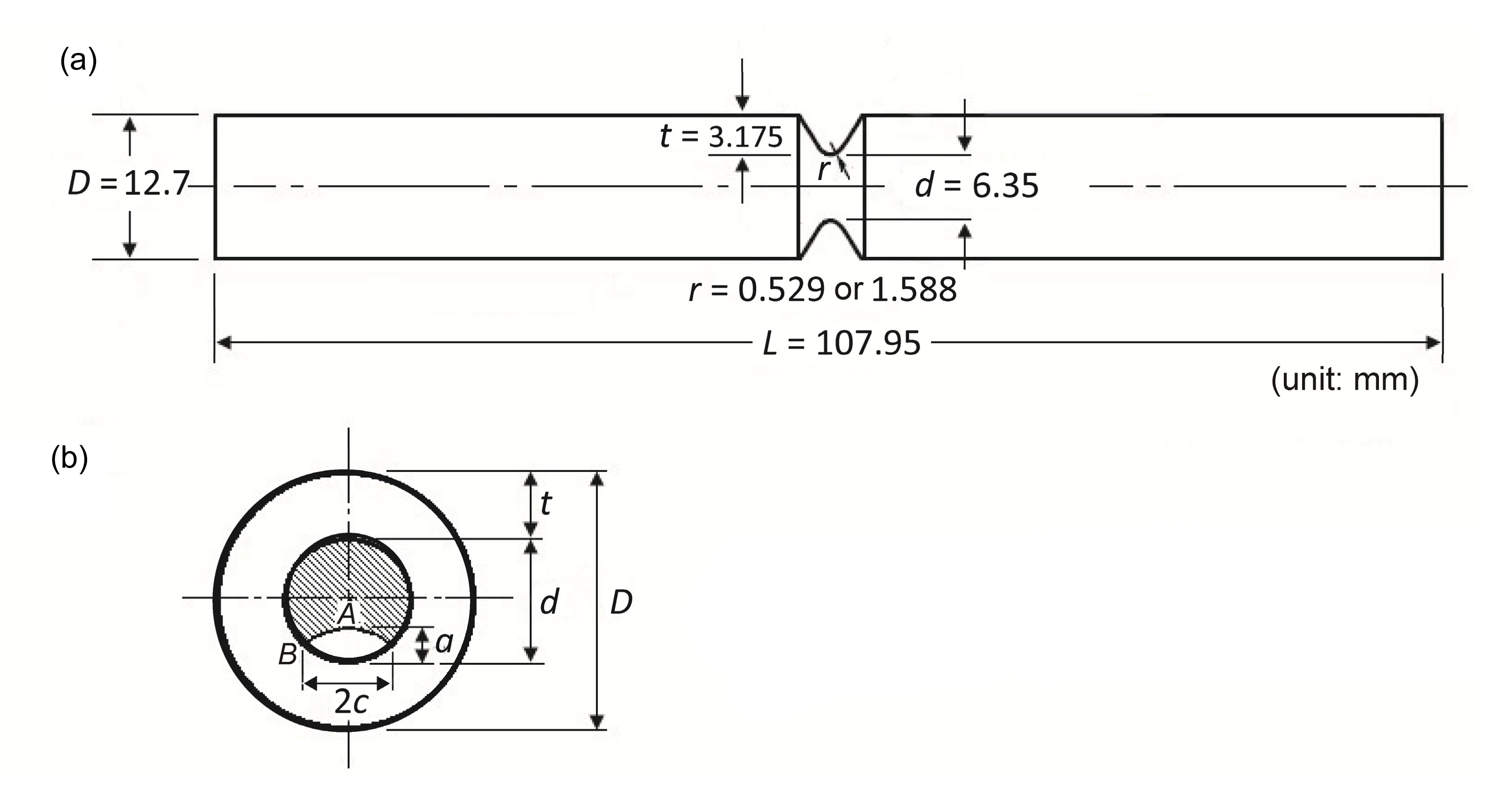
The model as shown in Fig. 1a is a circumferentially V-shaped notched round bar with an outer diameter D=12.7 mm, length L=107.95 mm, diameter of notch cross section d=6.35 mm, notch depth t=3.175 mm, notch opening angle equal to 60°, and a notch root radius r=0.529 mm or 1.588 mm. These geometries are similar to those used in (Zeng and Fatemi, 2001).
Fig.1 The geometrical detail of the circumferentially V-shaped notched round bar model (a) and the surface crack (b)
A semi-elliptical surface crack was introduced at the notch root. The crack plane was set to be normal to the axis of the round bar. The details of the crack depth a and the crack length c are depicted in Fig. 1b. Points A and B shown in Fig. 1b denote the depth point and the surface point on the crack front, respectively. Table 1 lists the mechanical and fracture properties of AZ-6A-T5 magnesium alloy that are used in the NASGRO equation.
Table 1
Mechanical and fracture properties of AZ-6A-T5 magnesium alloy
Item
Value
Modulus of elasticity (GPa)
45
Poisson’s ratio
0.35
Yield strength (0.2%) (MPa)
268.89
Ultimate tensile strength (MPa)
344.74
Plane stress fracture toughness, KC (MPa·mm1/2)
972.96
Plane strain fracture toughness, KIC (MPa·mm1/2)
694.97
Crack growth rate coefficient, C
7.96×10⁻¹⁰
NASGRO n exponent, n
2.58
NASGRO p coefficient, p
0.25
NASGRO q coefficient, q
0.25
Threshold SIF at R=0, ΔKth (MPa·mm1/2)
48.65
Plane stress/strain constraint factor, α
1.5
Ratio of the peak stress to the material flow stress in a stress cycle, Smax/S0
0.3
The generalized NASGRO equation is widely used in many practical simulations. The equation incorporates the fatigue crack closure feature by considering the effect of the stress ratio on crack growth rate (Newman et al., 1994):
,
where N is the fatigue loading cycles, a is the crack length (crack depth), R is the stress ratio, ΔKth is the threshold SIF, ΔK is the range of SIFs, KC is the plane stress fracture toughness, the constants C, n, p, and q are the NASGRO coefficients, and f is the crack opening function that is defined as (Newman et al., 1994)
and the polynomial coefficients are defined as (Newman et al., 1994):
,
,
,
,
where α is the plane stress/strain constraint factor, and Smax/S0 is the ratio of the peak stress (Smax) to the material flow stress (S0) in a stress cycle. The constants α and Smax/S0 are available as the fitting constants (BEASY, 2013).
2.2. Boundary element model
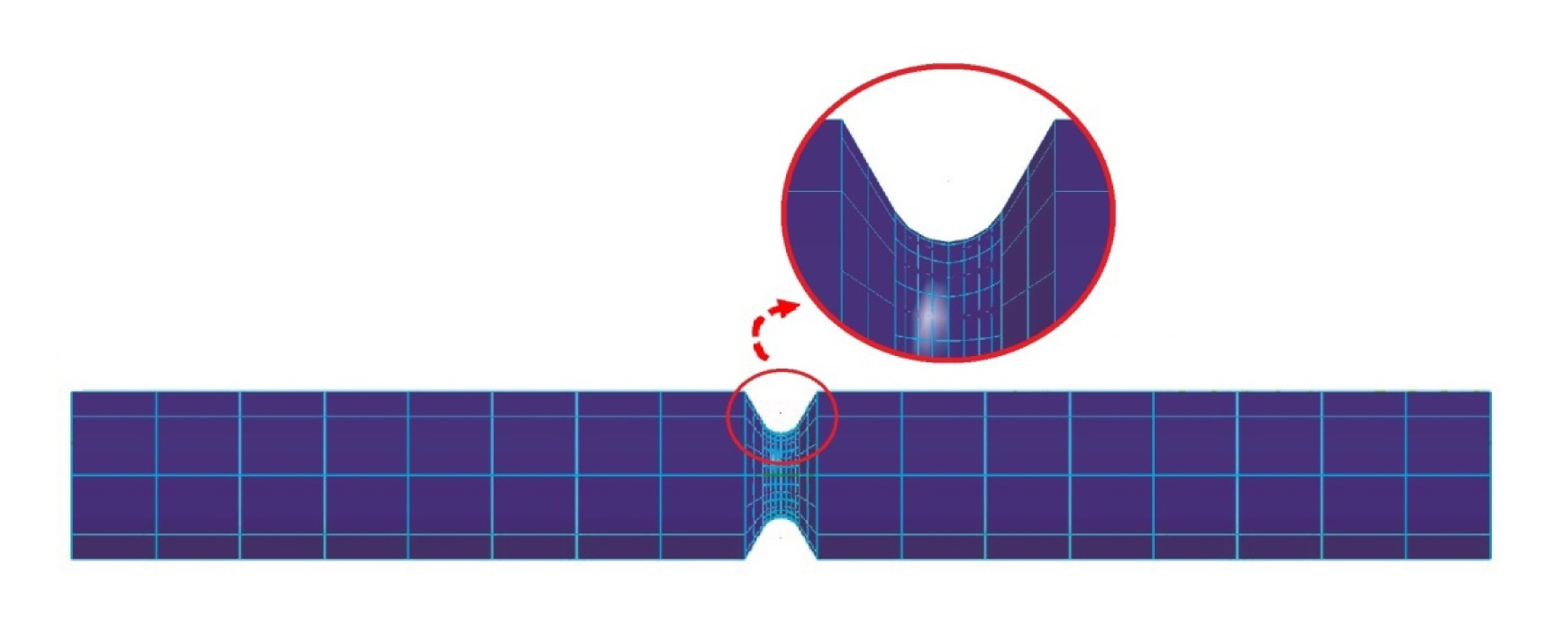
Linear quadratic elements (485 elements) were used to discretize the entire surfaces of the model as depicted in Fig. 2. To improve the accuracy of the stress and strain evaluations, the mesh size refinement of around 0.3 mm in the vicinity of the notch root was made. A uniform tensile stress of 30 MPa was applied to either end of the model, and a fixed-displacement boundary condition in x, y, and z directions was applied to another end. An initial elliptical surface crack was introduced on the notch root. The crack geometries are set to have a crack depth a=0.5 mm and the crack aspect ratios a/c=0.5, 1, and 2. Fatigue crack simulations with a constant amplitude loading R=0 were carried out.
Fig.2 Meshed V-shaped notched model
3. Results and discussion
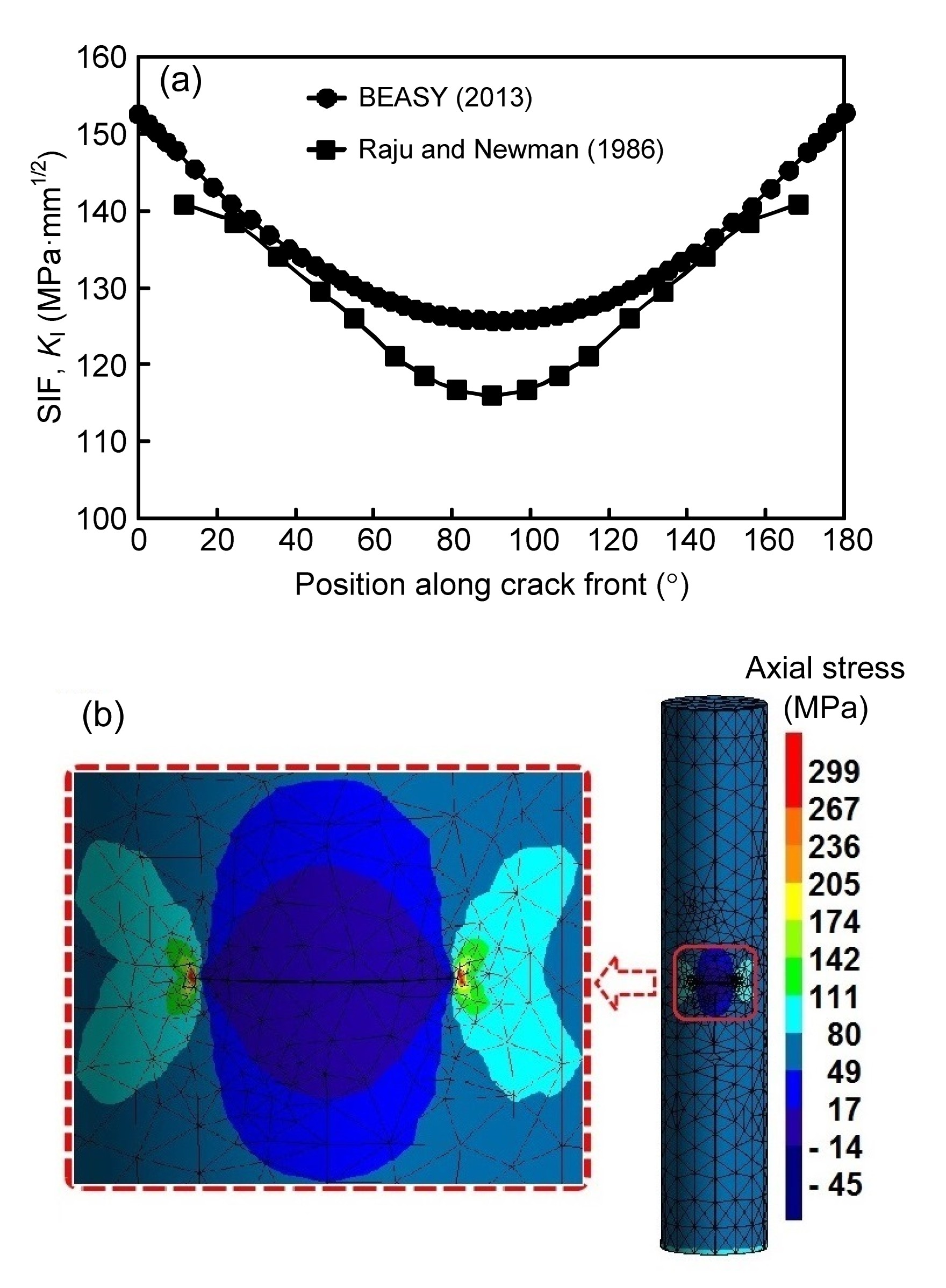
To demonstrate the accuracy of the results obtained by using BEASY (BEASY, 2013), a comparison of the SIFs for a semi-elliptical surface crack in a smooth round bar under a tensile load (70 MPa) with those of the Raju-Newman solution (Raju and Newman, 1986) was made and plotted in Fig. 3a. The diameter of the smooth round bar D is 10 mm, the crack depth a is 2 mm, and the crack length c is 2 mm. The stress intensity factor K0 shown in Fig. 3a is defined as
,
where σ is the applied remote tension stress. It can be seen from Fig. 3a that the results are shown to be in good agreement. The largest difference is found at the mid-point of the crack front and is within 8%. BEASY basically uses the dual boundary element method (DBEM) (Mi and Aliabadi, 1992) for 3D crack analysis. The axial stress contour around the crack tip and the mesh refinement generated using BEASY are shown in Fig. 3b.
Fig.3 Comparison of the SIFs for longitudinal semi-elliptical surface crack on a solid cylinder obtained by BEASY (2013) and Raju and Newman (1986) (a) and the corresponding axial stresses around the crack region (b)
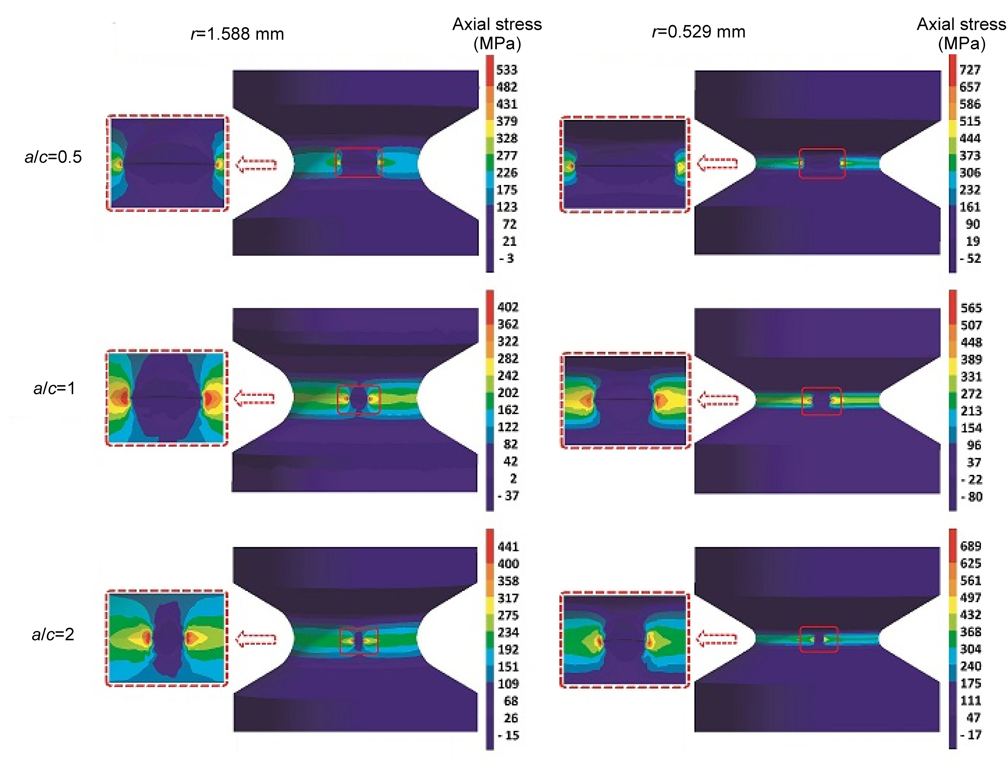
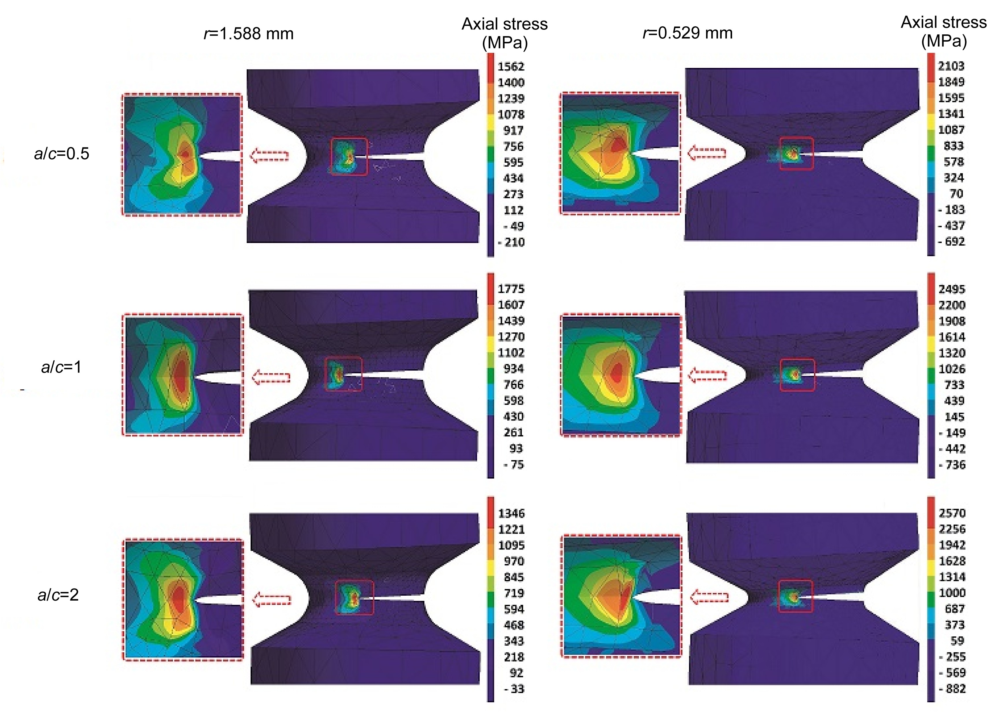
It can also be seen from Figs. 4 and 5 that the axial stress contours for the initial and final increments around the crack fronts and the final crack opening modes can be identified. For a given crack depth a, the axial stresses for cracks with a/c≠1 are shown to be larger than those for a/c=1. However, a greater axial stress around the crack front does not necessarily result in a higher SIF.
Fig.4 Axial stress contours at around the surface crack at the initial increment
Fig.5 Axial stress contours at around the surface crack at the final increment
The SIF values are largely dependent on the applied remote stress and geometry factors. Figs. 4 and 5 also show highly stressed zones around the notch root surface, causing the dislocations’ shielding stress. The shielding effect leads to the maximum elastic stress shifting away from the notch root surface as a result of a condition where the regions around the crack front would physically experience plastic deformation.
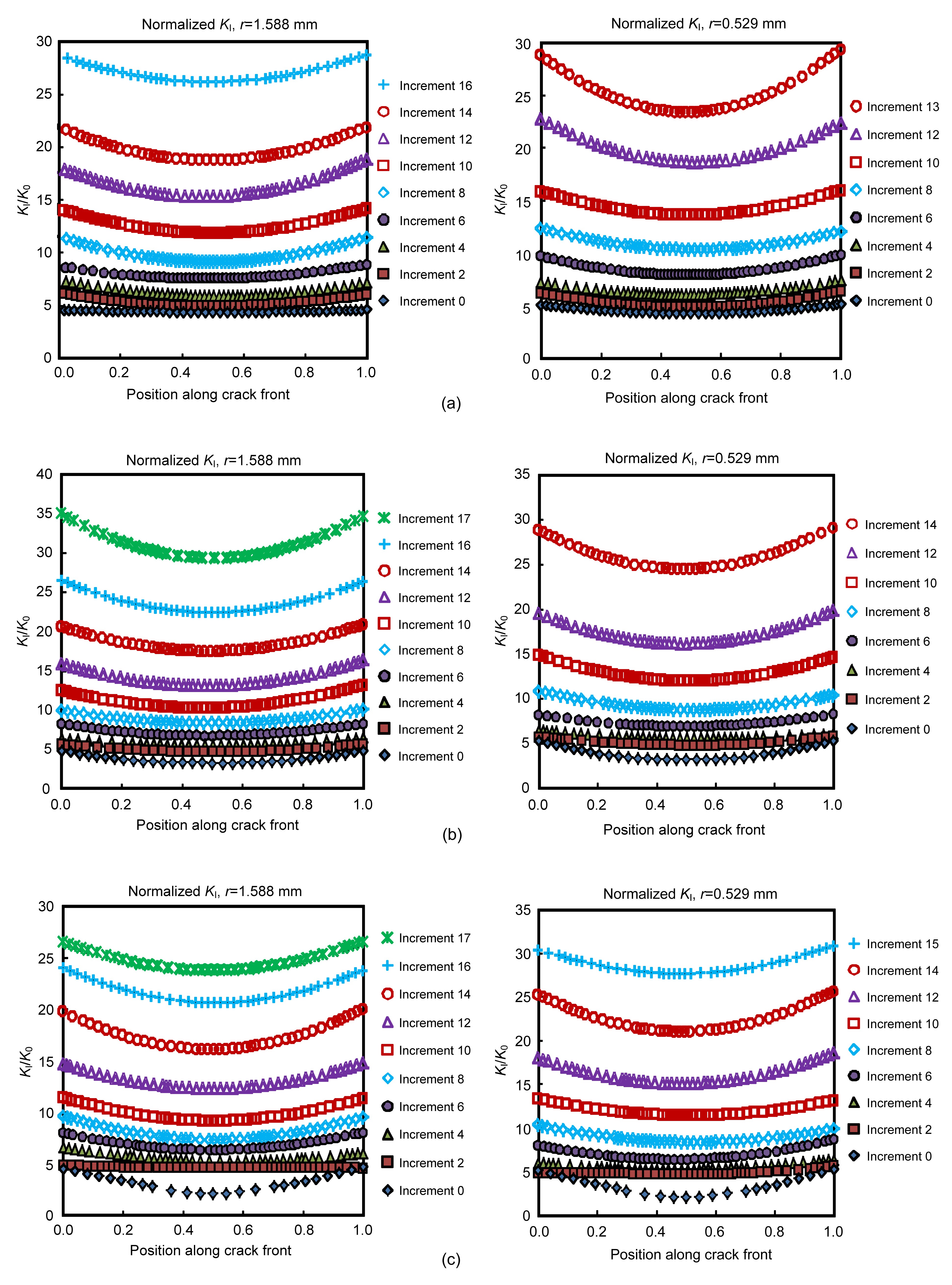
The normalized SIFs KI/K0 along the crack front for three different crack aspect ratios (a/c) and two different notch radii r of the selected increments during fatigue crack growths are presented in Fig. 6 (p.878). The mid-point of the elliptical crack front is defined as the point 0.5 of the x-axis, while the surface points of the crack front are denoted by the points 0 and 1. The maximum and minimum normalized SIFs along the crack front at each increment during the crack propagation are found at the crossed surface points and the mid-point, respectively. As expected, for a given crack aspect ratio, more fatigue loading cycles going to failure are seen in the blunt notch model compared to those of the sharp notch model. In all cases, the largest SIFs are found at the surface points.
Fig.6 Normalized SIFs for a=0.5 mm, c=1 mm (a); a=0.5 mm, c=0.5 mm (b); and a=0.5 mm, c=0.25 mm (c)
At the initial stage (increment 0), the SIFs along the crack front for a/c=0.5 are shown to have slightly different values (Fig. 6). Meanwhile, the differences in the SIF values along the crack front for the larger crack aspect ratios, i.e., a/c of 1 and 2, are noticeably larger as evidenced by the SIFs patterns which form a U-shaped curve. The SIF patterns along the crack front for the larger crack aspect ratios a/c tend to form flat-shaped curves in the first few increments and then appear to form U-shaped curves in the following increments. The shape evolution of the SIF patterns at the crack fronts for a/c=1 and 2 are shown to be different from those at the smaller crack aspect ratio (a/c=0.5), which immediately forms U-shaped curves until fracture. It may be estimated from Table 2 (p.879) that the unstable crack extensions during crack growth are observed when the crack aspect ratio a/c evolves to be between 0.6 and 0.7.
Table 2
Crack geometries during fatigue crack growths
c (mm)
Initial a/c
Increment
Notch radius, r=1.588 mm
Notch radius, r=0.529 mm
Total cycle
Crack depth,a (mm)
Crack length,c (mm)
Total cycle
Crack depth,a (mm)
Crack length,c (mm)
1
0.5
0
0
0.5000
0.9668
0
0.5000
0.9668
2
3738
0.9662
1.5325
3683
0.9253
1.6067
4
5998
1.3841
2.2242
5944
1.3358
2.3357
6
7332
1.8155
2.8784
7213
1.8066
3.0212
8
8063
2.2690
3.573
7866
2.3191
3.6378
10
8467
2.7462
4.175
8172
2.8609
4.1712
12
8693
3.3587
4.6655
8316
3.4837
4.6829
13
8760
3.6587
4.8955
8330
3.8548
4.9431
14
8811
3.9683
5.1146
16
8848
4.5750
5.5344
0.5
1
0
0
0.5000
0.4997
0
0.5000
0.4997
2
4910
0.8733
1.3296
4779
0.8349
1.4631
4
7729
1.3079
1.9576
7553
1.2873
2.0498
6
9450
1.7554
2.5767
9230
1.7324
2.6441
8
10 412
2.1671
3.2353
10 134
2.1579
3.3089
10
10 940
2.5793
3.8609
10 543
2.6329
3.9114
12
11 245
3.0940
4.4315
10 740
3.1960
4.4658
14
11 413
3.7172
4.9134
10 804
3.9296
4.9937
16
11 490
4.3289
5.3469
17
11 490
4.8035
5.5857
0.25
2
0
0
0.5000
0.2501
0
0.5000
0.2501
2
6289
0.7873
1.1688
5289
0.7426
1.2410
4
9546
1.2562
1.7199
8525
1.1963
1.8579
6
11 419
1.6680
2.3985
10 375
1.6021
2.5568
8
12 527
2.0801
3.0590
11 318
2.0028
3.2369
10
13 211
2.4934
3.6706
11 814
2.4935
3.8144
12
13 560
2.8989
4.2853
12 049
3.0515
4.3357
14
13 770
3.5525
4.7649
12 154
3.7187
4.8559
15
13 824
3.8344
5.0019
12 157
4.0326
5.1343
16
13 861
4.1219
5.2197
17
13 877
4.4347
5.4267
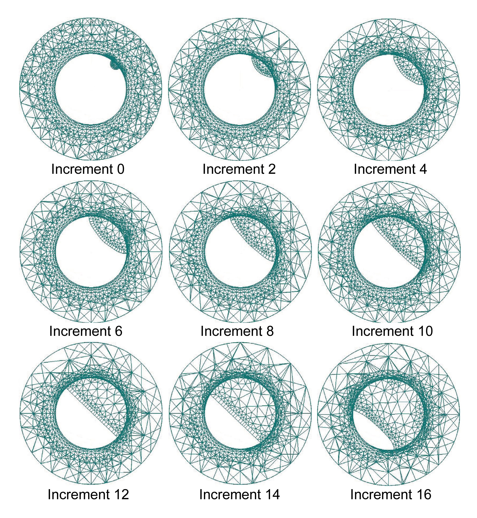
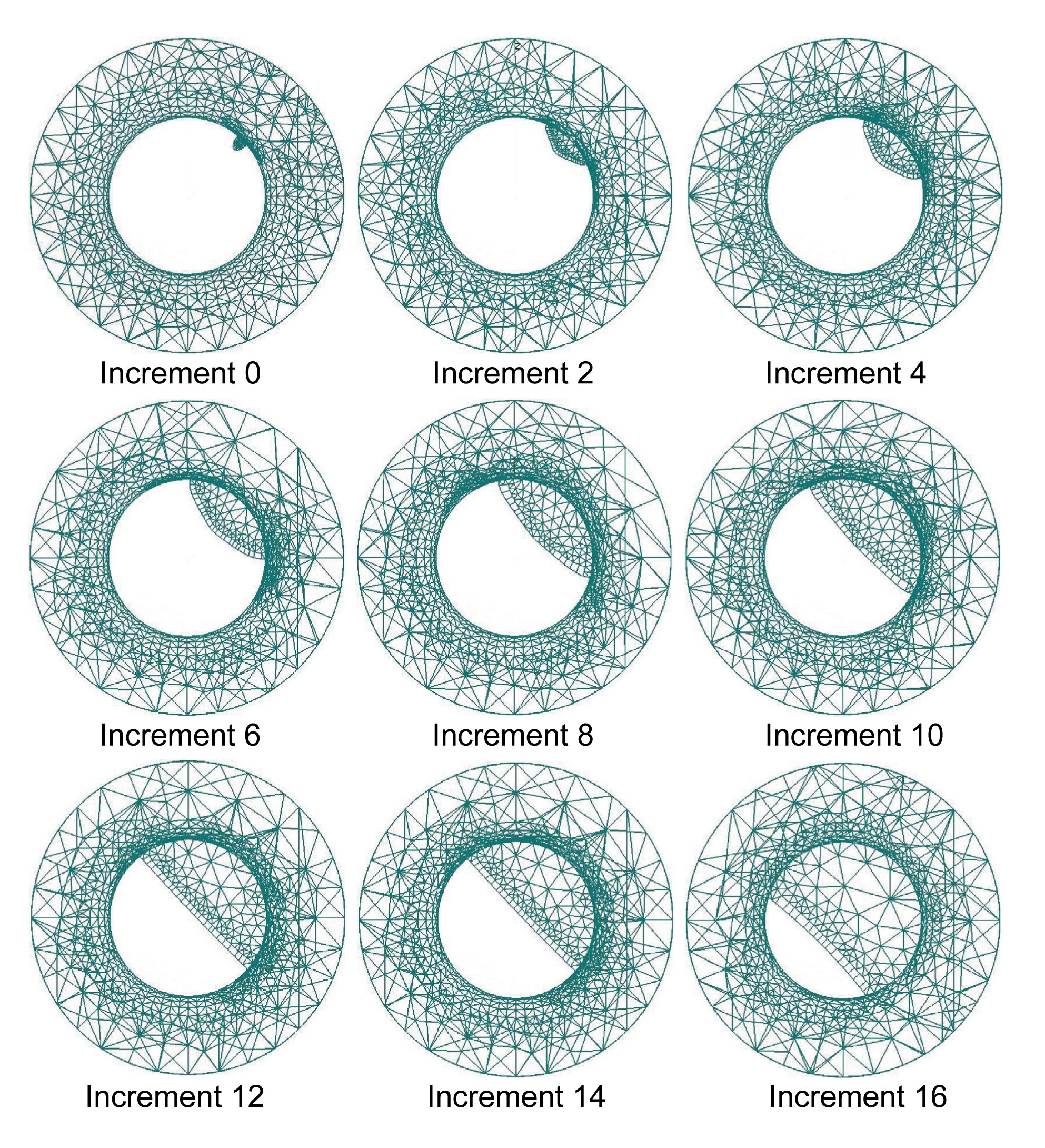
The crack shape evolutions for three different crack aspect ratios and two different notch radii are depicted in Figs. 7–12 (p.880–881). At the initial increment of the crack growth, the crack surfaces form an almond shape. Then, in the following increments, the shapes of the cracks evolve to form a nearly straight line at the crack front. It can also be observed from Figs. 7–12 that unstable crack growth is observed after the crack front has formed a straight shape. A careful consideration should be taken if the cylinder contains a defect like a ‘shallow surface crack’ with a straight crack front shape or with a smaller crack aspect ratio. Previous studies on the crack shape evolutions of a surface crack in smooth and notched cylinders have been reported (Carpinteri, 1993; Carpinteri and Brighenti, 1996; Lin and Smith, 1998; Carpinteri et al., 2006; 2013). They used linear Paris’s equation for the crack growth simulations. Paris’s equation does not consider the effect of crack closure during the crack growth, resulting in very conservative estimations and much shorter fatigue lives. Figs. 7–12 also show that the size of the initial crack aspect ratio would have a significant influence on the crack shape evolution during the crack growth.
Fig.7 Crack shape evolutions for a/c=0.5 and r=1.558 mm
Fig.8 Crack shape evolutions for a/c=1 and r=1.558 mm
Fig.9 Crack shape evolutions for a/c=2 and r=1.558 mm
Fig.10 Crack shape evolutions for a/c=0.5 and r=0.529 mm
Fig.11 Crack shape evolutions for a/c=1 and r=0.529 mm
Fig.12 Crack shape evolutions for a/c=2 and r=0.529 mm
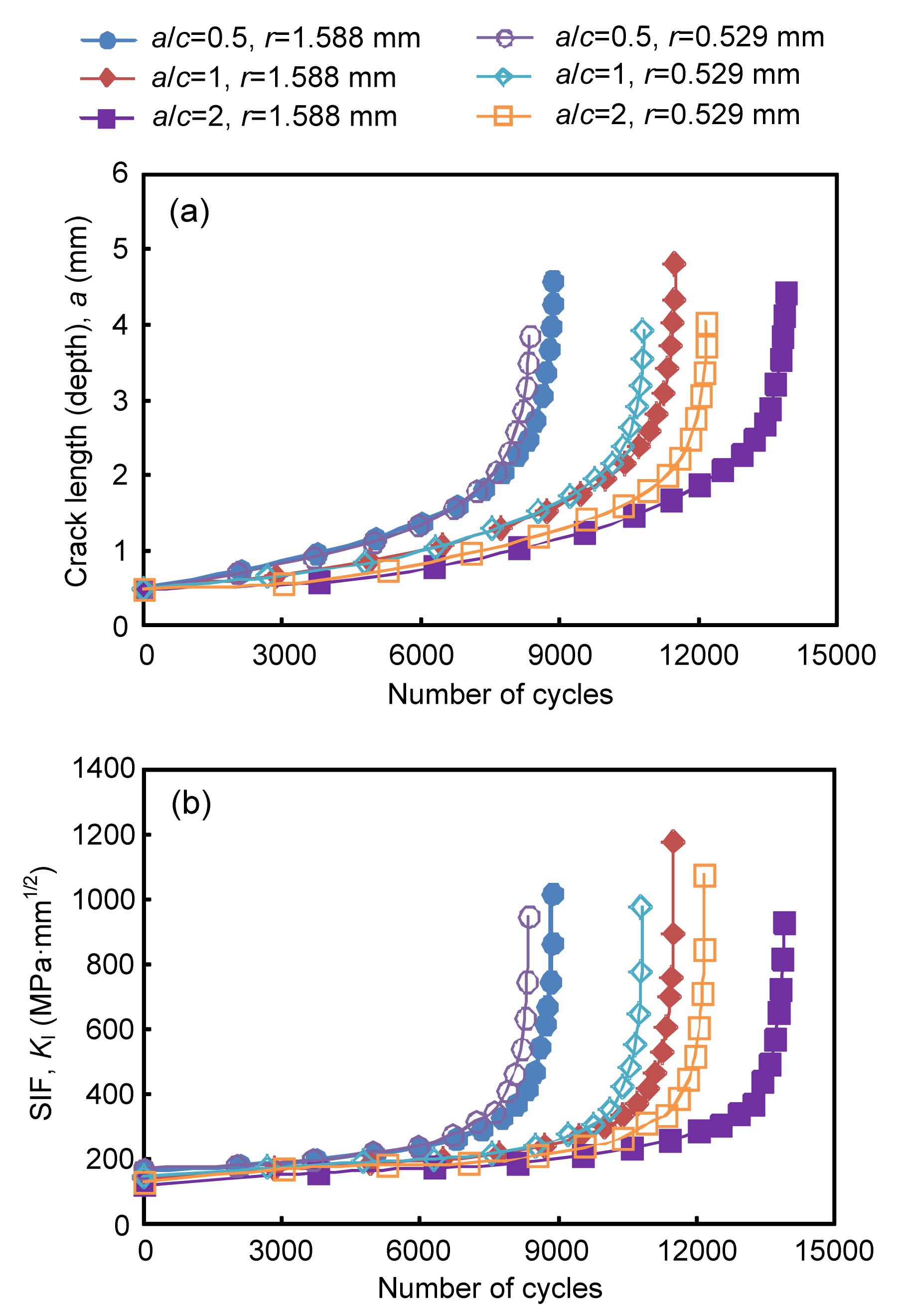
Fig. 13a (p.881) shows that a smaller crack aspect ratio clearly leads to a shorter fatigue life. The effect of the crack aspect ratio on the fatigue life is shown to be more significant than the notch radius. Unstable crack growth is expected when the corresponding stress intensity factor KI approaches the plane strain fracture toughness. It can be seen from Fig. 13b that unstable crack growths begin to happen when the SIF of the cracks is about 400 MPa·mm1/2 (see Table 1 for the plane strain fracture toughness). The specimens fail when the SIFs attain the plane stress fracture toughness.
Fig.13 Fatigue life versus crack length (depth), a (a) and the SIFs, KI (b)
4. Conclusions
Fatigue growths of a semi-elliptical surface crack in a V-shaped notched round bar subjected to uniform cyclic tension have been analyzed. A few statements are presented as follows:
The size of the initial crack aspect ratio has significant influence on the crack shape evolution during crack growth.
The effect of the crack aspect ratio on fatigue life is more significant than the notch radius.
Unstable crack growth was observed when the crack front had evolved to form a straight shape.
For a given crack depth, smaller crack aspect ratios lead to shorter fatigue lives.
The unstable crack extension during the crack growth was observed when the crack aspect ratio a/c evolved to be between 0.6 and 0.7.
[2] Carpinteri, A., 1993. Shape change of surface cracks in round bars under cyclic axial loading. International Journal of Fatigue, 15(1):21-26.
[3] Carpinteri, A., Brighenti, R., 1996. Part-through cracks in round bars under cyclic combined axial and bending loading. International Journal of Fatigue, 18(1):33-39.
[4] Carpinteri, A., Brighenti, R., Vantadori, S., 2006. Surface cracks in notched round bars under cyclic tension and bending. International Journal of Fatigue, 28(3):251-260.
[5] Carpinteri, A., Ronchei, C., Vantadori, S., 2013. Stress intensity factors and fatigue growth of surface cracks in notched shells and round bars: two decades of research work. Fatigue & Fracture of Engineering Materials & Structures, 36(11):1164-1177.
[6] Guo, W., Shen, H., Li, H., 2003. Stress intensity factors for elliptical surface cracks in round bars with different stress concentration coefficient. International Journal of Fatigue, 25(8):733-741.
[7] Lin, X.B., Smith, R.A., 1998. Fatigue growth simulation for cracks in notched and unnotched round bars. International Journal of Mechanical Science, 40(5):405-419.
[8] Lin, X.B., Smith, R.A., 1999. Shape evolution of surface cracks in fatigued round bars with a semi-circular circumferential notch. International Journal of Fatigue, 21(9):965-973.
[9] Mi, Y., Aliabadi, M.H., 1992. Dual boundary element method for three-dimensional fracture mechanics analysis. Engineering Analysis with Boundary Elements, 10(2):161-171.
[10] Newman, J.C., Forman, R.G., DeKoning, A.U., 1994. Fatigue Crack Growth Computer Program NASA/FLAGRO Version 2.0. Report JSC-22267A. National Aeronautics and Space Administration,USA :
[11] Raju, I.S., Newman, J.C., 1986. Stress-intensity factors for circumferential surface cracks in pipes and rods under tension and bending loads. ASTM Special Technical Publication, 905:789-805.
[12] Shih, Y.S., Chen, J.J., 2002. The stress intensity factor study of an elliptical cracked shaft. Nuclear Engineering and Design, 214(1-2):137-145.
[13] Shin, C.S., Cai, C.Q., 2004. Experimental and finite element analyses on stress intensity factors of an elliptical surface crack in a circular shaft under tension and bending. International Journal of Fracture, 129(3):239-264.
[14] Zeng, Z., Fatemi, A., 2001. Elasto-plastic stress and strain behavior at notch roots under monotonic and cyclic loadings. The Journal of Strain Analysis for Engineering Design, 36(3):287-300.
Open peer comments: Debate/Discuss/Question/Opinion


Open peer comments: Debate/Discuss/Question/Opinion
<1>