Affiliation(s):
1.
Department of Engineering Mechanics, China University of Petroleum, Qingdao 266580, China; moreAffiliation(s): 1.
Department of Engineering Mechanics, China University of Petroleum, Qingdao 266580, China; 2.
Department of Engineering Mechanics, Shanghai Jiao Tong University, Shanghai 200240, China; less
Xiao-guang Huang, Jin-quan Xu. 3D analysis for pit evolution and pit-to-crack transition during corrosion fatigue[J]. Journal of Zhejiang University Science A, 2013, 14(4): 292-299.
@article{title="3D analysis for pit evolution and pit-to-crack transition during corrosion fatigue", author="Xiao-guang Huang, Jin-quan Xu", journal="Journal of Zhejiang University Science A", volume="14", number="4", pages="292-299", year="2013", publisher="Zhejiang University Press & Springer", doi="10.1631/jzus.A1200273" }
%0 Journal Article %T 3D analysis for pit evolution and pit-to-crack transition during corrosion fatigue %A Xiao-guang Huang %A Jin-quan Xu %J Journal of Zhejiang University SCIENCE A %V 14 %N 4 %P 292-299 %@ 1673-565X %D 2013 %I Zhejiang University Press & Springer %DOI 10.1631/jzus.A1200273
TY - JOUR T1 - 3D analysis for pit evolution and pit-to-crack transition during corrosion fatigue A1 - Xiao-guang Huang A1 - Jin-quan Xu J0 - Journal of Zhejiang University Science A VL - 14 IS - 4 SP - 292 EP - 299 %@ 1673-565X Y1 - 2013 PB - Zhejiang University Press & Springer ER - DOI - 10.1631/jzus.A1200273
Abstract: This paper presents a deterministic model to predict the pitevolving morphology and crack initiation life of corrosion fatigue. Based on the semi-ellipsoidal pit assumption, the thermodynamic potential including elastic energy, surface energy and electrochemical energy of the cyclically stressed solid with an evolving pit is established, from which specific parameters that control the pit evolution are introduced and their influence on the pit evolution are evaluated. The critical pit size for crack nucleation is obtained from stress intensity factor criterion and the crack nucleation life is evaluated by Faraday’s law. Meanwhile, this paper presents a numerical example to verify the proposed model and investigate the influence of cyclic load on the corrosion fatigue crack nucleation life. The corrosion pit appears approximately as a hemisphere in its early formation, and it gradually transits from semicircle to ellipsoid. The strain energy accelerates the morphology evolution of the pit, while the surface energy decelerates it. The higher the stress amplitude is, the smaller the critical pit size is and the shorter the crack initiation life is.
Darkslateblue:Affiliate; Royal Blue:Author; Turquoise:Article
Article Content
1. Introduction
Corrosion fatigue has been found to be responsible for the degradation and failure of many metallic materials and structures (Ruiz and Elices, 1997; Zupanc and Grumb, 2010; Palin-Luc et al., 2010). A corrosive environment assists corrosion pit formation, pit evolution and eventually leads to fatigue crack initiation and growth to failure (Ishihara et al., 2008; 2010; Bhuiyan et al., 2008). The overall process of corrosion fatigue fracture includes the following fundamental steps: pit initiation, pit growth, the transition from pit to crack, crack growth and fracture. However, the evolution of the pit until its transition to a crack in the preliminary stages may occupy the most significant portion of the life (Ebara, 2007), which is extremely important for the feasibility of predicting this stage of the damage process.
A pit almost always initiates at some chemical or physical heterogeneity on the surface (Ma et al., 2010). Materials such as high-strength aluminum alloys and stainless steel contain numerous constituent particles, which play important roles in corrosion pit formation. Pit shape depends mainly on electrochemical processes in the metal/electrolyte interface and potential distribution inside the cavity (Liao and Wei, 1999; Wang et al., 2001; Perkins and Bache, 2005). Wei (2001) identified that pit growth was controlled by the limiting cathodic current density supported by the exposed constituent/impurity particles within a growing pit. Codaro et al. (2002) and Ghali and Dietzel (2004) indicated that the surface texture of a pit including its size and shape was directly decided by the value of potential due to the electrochemical reaction in the pit. However, neither effect of the electrochemical reaction nor influence of fatigue stressing considered during pitting has been clearly brought out in its formulation. Ernst et al. (1997) indicated that an open hemispherical pit was unstable because the concentration of dissolved cations failed well below saturation near the rim of the pit, leading to passivation. The pit morphology appeared in hemispherical shape at the early stage of growth and it tended to transit from hemispherical to cylindrical or dish shape. Harlow and Wei (1994) assumed that the pit took the shape of a semi-sphere and grew at an equal rate at all directions, and obtained the equation of pit depth varying over time. Rokhlin et al. (1999) predicted a steadily decreasing rate of pit growth with time. Harlow and Wei (1998) assumed the actual shape of the pit to be half of a prolate spheroid, and proposed three approaches for pit growth: constant aspect ratio, discrete time-dependent aspect ratio and continuous time-dependent aspect ratio. Turnbull et al. (2006a; 2006b) proposed a mathematical model to simulate the evolution of corrosion pits and the transition from corrosion pits to stress corrosion cracks. Valor et al. (2007) established a stochastic model of pitting corrosion to depict corrosion pit initiation and growth.
In spite of the advances achieved in pit initiation, evolution and its transition to crack, the modeling of the pit evolution process is still an open question. In this paper, we focus on the thermodynamic framework of pit evolution during the corrosion fatigue process. Pit evolution is an irreversible thermodynamics process, and the variation of thermodynamic potential during pit growth may incite the diffusion on pit surface, which also affects the evolving morphology of the pit. A thermodynamic potential, including elastic energy, surface energy and electrochemical energy, is formulated for a 3D cyclically stressed solid with a corrosion pit varying in shape and volume, from which the actual evolving morphology is obtained. The critical pit morphology for crack nucleation and the corrosion fatigue crack nucleation life are also discussed in this paper.
2. Energetics of elastic solid with an evolving corrosion pit
2.1. Modeling of the evolving pit
Fig. 1 shows the 3D model of an evolving pit in the semi-infinite elastic solid. The pit evolves with the interaction of corrosion media and cyclic remote stress; the solid varies its elastic field and morphology of the pit. Based on the symmetry of the problem, the evolution of the pit can be assumed as a sequence of semi rotating ellipsoids. The cross-section of the pit in the xy plane maintains a semicircle for the remote stresses σx, σy both equal to zero. Let a, b and c be semi-axes in x, y and z directions, respectively,
,
where m is the shape parameter of the semi-ellipsoidal pit, −1<m<1, r is the equivalent radius of the hemisphere having the same volume with the semi-ellipsoidal pit. The hemisphere corresponds to m=0, the xy direction crack to m→1, and the thin-strip vertical crack to m→−1.
Fig.1 Semi-ellipsoidal pit in semi-infinite elastic solid during corrosion fatigue σ: cyclic stress, σ0: average stress, σa: stress amplitude, ω: frequency, t: time
According to the semi-ellipsoid assumption, the actual morphology can be indicated as the sequence of shape parameter m and equivalent radius r, though the pit always changes its morphology during evolving process.
2.2. Thermodynamic potential of elastic solid with an evolving corrosion pit
The thermodynamic potential of elastic solid consists of elastic energy, surface energy and electrochemical energy. When the pit evolves constantly under the interaction of the corrosion environment and cycle stress, the pit varies its shape and size, the solid varies its elastic energy and surface energy, and the anodic dissolution of the pit releases electrochemical energy. Thus, the thermodynamic potential Φ can be seen as a function of pit shape, pit volume and the applied cyclic load. The thermodynamic potential of the elastic solid with an evolving pit can be expressed as
,
where UE is the strain energy, UC is the released electrochemical energy during the corrosion process, and US is the surface energy.
As the pit varies its morphology during corrosion fatigue, the semi-infinite elastic solid containing a semi-ellipsoidal pit subjected to remote cyclic stress stores an infinite amount of strain energy. Yet, the energy difference between the solid containing a semi-ellipsoidal pit and the solid without a pit subjected to the same stresses can be computed by the Eshelby inclusion theory (Eshelby, 1957; Wang and Li, 2004a; 2004b)
,
where E is Young’s modulus, σ is the remote cyclic stress, and B is a dimensionless coefficient, as a function of the shape parameter m and the Poisson’s ratio ν, specifically expressed as
,
where Sij (i,j=1,2,3) are the components of Eshelby tensor (Eshelby, 1957).
When the initial pit grows to a random state, with the equivalent radius varying from r0 to r, the elastic energy differs by
,
where r0 and B0 is r and B for the initial pit, respectively.
The surface area of the pit changes during the evolving process, leading to the variation of surface energy. The dimensionless coefficient A is (Wang et al., 2004),
,
where .
The surface area of the pit is written as
,
then the variation of the surface energy is ,
where γS is the surface energy per area on the pit surface, and A0 is A for the initial pit.
Let ρ be the density, M be the molecular quality, and n be valence, the power of the dissolved anode metal is
,
where F is the Faraday constant.
According to the electrochemical mechanism of corrosion, the anodic potential of the corrosion electrochemical reaction can be expressed as
,
where is the metal’s standard electrode potential, R is the universal gas constant, T is the absolute temperature, and is the activity of metal ion.
Assuming the anodic potential remains unchanged during pit evolution, the variation of electrochemical energy is
.
Thus, the variation of thermodynamic potential ΔΦ can be rewritten as
.
2.3. Evolving morphology of corrosion pit
According to the second law of thermodynamics, the system energy dissipation rate is positive during the evolution of the pit; consequently, the thermodynamic potential decreases continuously. However, among all possible morphologies of the pit, the actual pit morphology minimizes Φ. Expanding Eq. (12) in powers of r and m,
.
Here, only three leading terms are retained for small m. Obviously, the theoretical pit shape requires , i.e., ,
where is an elastic energy-related parameter, and , is a parameter about electrochemical energy released by metal anodic dissolution.
The actual pit shape m is determined by
,
where
From Eq. (15) we can find that the shape parameter changes continuously with the variation of r. However, the variation of shape parameter with r must be within the range −1<m<1. Otherwise, the pit evolution is extremely unstable and collapses into a crack quickly.
2.4. Sensitivity analysis during the pit evolution
The pit shape during corrosion fatigue is mainly controlled by the variation of strain energy and surface energy. To quantitatively analyze the influence of strain energy and surface energy on the shape parameter, the sensitivity coefficient of strain energy and surface energy are introduced.
,
.
3. Corrosion fatigue crack nucleation
Fatigue crack is observed to nucleate and propagate from a corrosion pit, and a corrosion pit leading to corrosion fatigue crack nucleation and growth is considered to be a most significant degradation mechanism. Kondo (1987) proposed the transition model for pit to corrosion fatigue crack nucleation. In the corrosion fatigue process, the pit predominates in the early stage and is replaced by fatigue crack growth, based on two criteria: stress intensity factor and the competition between pit growth and crack growth (Chen et al., 1996), i.e.,
,
where ΔKth is the threshold driving force, a is the pit depth or crack length, and is the evolving rate of pit depth or crack growth rate.
When the pit reaches a critical morphology that satisfies the threshold requirement for crack initiation, the pit is ready for ‘‘transition’’ into a crack, which essentially means that the kinetics of crack extension exceeds the pit growth rate at this moment, thus resulting in the crack taking over the damage mechanism.
According to the stress intensity factor criterion, the critical pit size at which a crack nucleates can be expressed in terms of the threshold driving force via the crack growth mechanism. According to the previous assumption of the pit, the semi-infinite elastic solid containing a semi-ellipsoidal surface is equivalent to an infinite plate consisting of semicircular surface flaws in 2D, and the expression for the stress intensity factor range ΔK for a pitted surface can be written as (Harlow and Wei, 2001; Wang et al., 2001; Sriraman and Pidaparti, 2010)
,
where is the stress range, and Kt is the stress concentration factor resulting from a circular rivet hole.
Thus, the critical pit depth acr when crack nucleates is found to be
.
Rewriting Eq. (13) in terms of m and a by introducing Eq. (1), the critical shape parameter mcr when crack nucleates can be obtained and the actual pit morphology is determined. Applying Faraday’s law (Rajasankar and Iyer, 2006),
,
where V is the volume of pit, t is the time, IP0 is the pitting current coefficient, depending on the clustered particles, and ΔH is the activation energy.
Integrating Eq. (21), we have
,
where ΔV is the volume of dissolved metal when a crack nucleates, a0 and m0 are the a and m when pit initiates.
The corrosion fatigue crack nucleation life for corrosion fatigue is written as .
Substituting tp-c=Np-c/f into Eq. (23), where Np-c is the number of stress cycles for crack nucleation and f is the frequency, we obtain:
.
4. Results and discussion
To make predictions of the pit evolving morphology and crack nucleation life through the developed model, an ideal 3D elastic solid of aluminum alloy has been considered. The relative parameters are mainly taken from (Sriraman and Pidaparti, 2010):
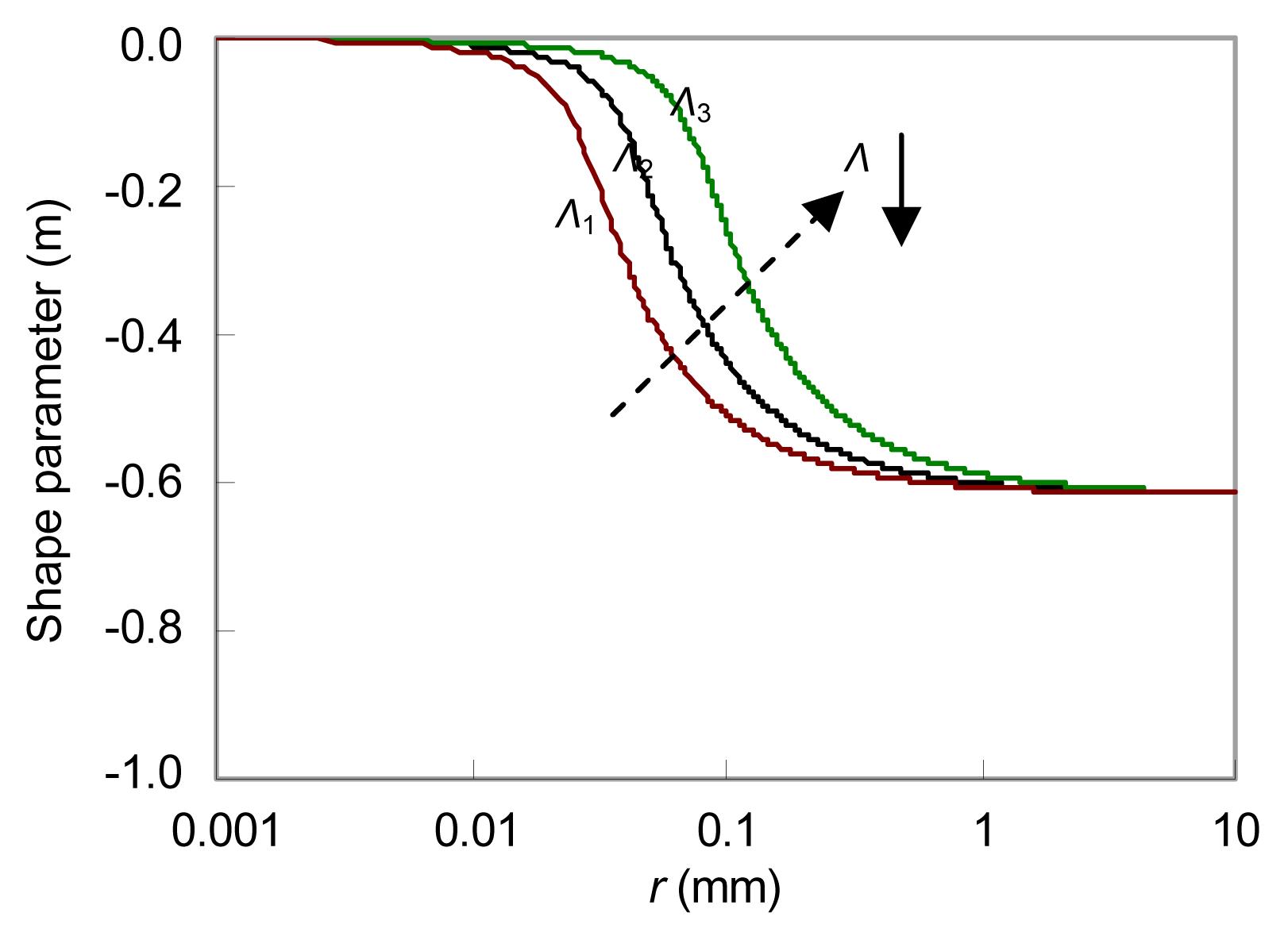
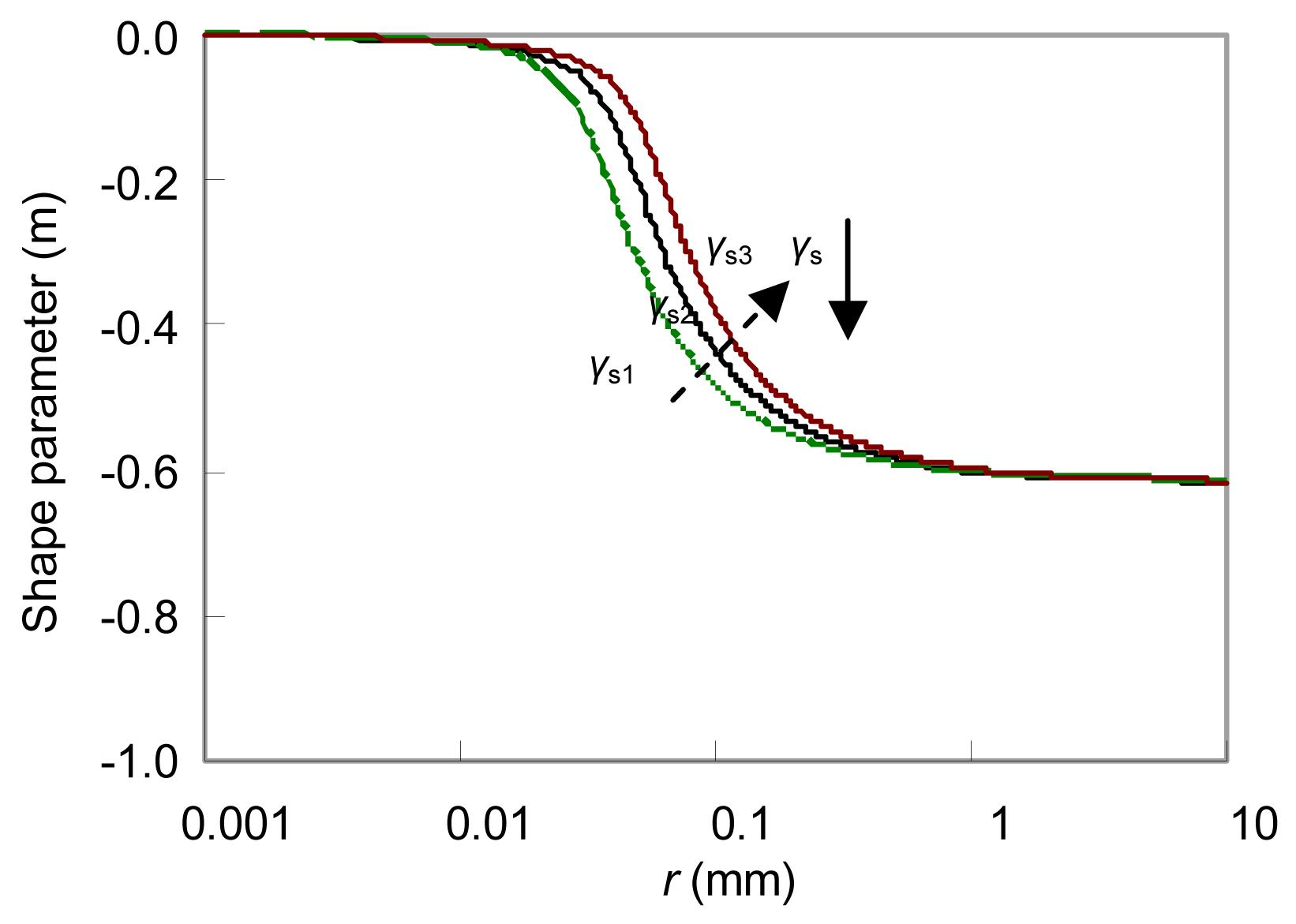
The influences of Λ and γS on shape parameter m varying with equivalent radius r are shown in Figs. 2 and 3. It can be seen that the morphology of the initial pit is approximately a hemisphere and the pit morphology gradually evolves into a semi-ellipsoidal with shape parameter close to a stable value. The actual shape parameter of the pit can be seen as the outcome of the interaction between the variation in the strain energy and surface energy. The strain energy is the propulsion of pit evolution. The higher Λ is, the more notable influence elastic energy has on the shape parameter of the pit. The pit is more likely to change its shape and stabilize to the determinate value at a higher Λ level. The surface energy is the obstruction of pit evolution. The effect of surface energy on the pit’s shape becomes significant with the rise of γS. The pit is inclined to maintain the initial shape of a hemisphere, and the change of shape parameter of the pit becomes difficult with the increase of r at higher γS levels.
Fig.2 Influence of r on shape parameter m at different Λ levels
Fig.3 Influence of r on shape parameter m at different γs levels
The sensitivity coefficients of mΛ
and mγS varying with r are displayed in Fig. 4. During the decreasing process of m with r, the strain energy promotes the morphology evolution of the pit, while the surface energy decelerates it. The actual morphology of the pit is the competing result of strain energy and surface energy, and this competition appears most obviously at a certain rm (0.036 mm).
Fig.4 Variation of mΛ and mγS with r
The strain energy fluctuates during every stress cycle, causing the fluctuation of shape parameter with r. The influence of cyclic stress σ on shape parameter m at certain levels of r (r=0.01, 0.1, 1.0 mm) is shown in Fig. 5. The influence of σ on m is significant at r=0.1 mm, while such influence weakens at r=0.01 mm and r=1.0 mm.
Fig.5 Influence of cyclic stress σ on shape parameter m at certain r (0.01, 0.1, 1 mm)
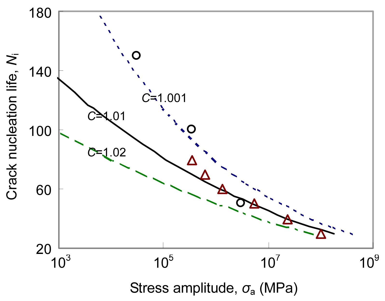
The predictions made from our model with respect to the crack initiation lives at different stress amplitudes are shown as open triangles in Fig. 6. The crack nucleation life decreases with increasing stress levels, as critical pit depth is inversely proportional to the stress amplitude. We can see that a crack initiates from relatively small pits at higher stress levels. Ishihara et al. (2006) carried out the tension-compression fatigue tests of aluminum alloy 2024-T3 in 3% NaCl solution, and analyzed the effects of stress amplitude and stress cyclic frequency on the corrosion pit growth behavior. Sriraman and Pidaparti (2010) introduced a stress-dependent function Cσa (C is the parameter introduced by Ishihara et al. (2006) to study the influence of stress amplitude on crack nucleation life. To verify the validity of the prediction model in this study, the experimental data from Ishihara et al. (2006) and the crack nucleation life vs. stress amplitude decreasing curves at different C levels from Sriraman and Pidaparti (2010) are shown in Fig. 6 for comparison. The predicted data points seem to agree well with the three data points of Ishihara et al. (2006), and actually fall within the curves corresponding to C=1.001–1.02. While, being a deterministic approach, our single-pit prediction model may withstand the limitations by the fact that plural corrosion pits stochastically initiated on the specimen surface.
Fig.6 Predicted number of cycles in open triangles for crack initiation life at different stress amplitude level The hollow circles correspond to the experimental values from Ishihara et al. (2006), and the decreasing curves at different C levels correspond to the prediction model of Sriraman and Pidaparti (2010)
5. Conclusions
A two-variable semi-ellipsoidal model is proposed to depict the pit’s evolving morphology. Based on the energy principle, an explicit expression to predict the actual evolving morphology of the pit is obtained. According to the stress intensity factor criterion, the critical pit depth is determined and the fatigue crack nucleation life is discussed.
The corrosion pit appears approximately as a hemisphere in its early stage of growth, and its morphology tends to transit from semicircle to ellipsoid with shape parameter gradually close to a stable value. The actual shape parameter of a pit can be seen as the outcome of the interaction between the variation in the elastic energy and surface energy; the strain energy accelerates the morphology evolution of the pit, while the surface energy decelerates it.
Stress amplitude has a significant effect on the critical pit size for crack nucleation and crack initiation life. The higher the stress amplitude is, the smaller the critical pit size is and the shorter crack initiation life is. The predictions of crack initiation life at different stress amplitude levels are found to be in fair agreement with the data available in the literature.
Acknowledgements
The authors would like to thank Mr. Feng SUN, China University of Petroleum for his help in English writing.
[1] Bhuiyan, M.S., Mutoh, Y., Murai, T., Iwakami, S., 2008. Corrosion fatigue behavior of extruded magnesium alloy AZ61 under three different corrosive environments. International Journal of Fatigue, 30(10-11):1756-1765.
[2] Chen, G.S., Wan, K.C., Gao, M., Harlow, D.G., Wei, R.P., 1996. Transition from pitting to fatigue crack growth-modeling of corrosion fatigue crack nucleation in a 2024-T3 aluminum alloy. Materials Science and Engineering: A, 219(1-2):126-132.
[3] Codaro, E.N., Nakazato, R.Z., Horovistiz, A.L., Ribeiro, L.M.F., Ribeiro, R.B., Hein, L.R.O., 2002. An image processing method for morphological characterization and pitting corrosion evaluation. Materials Science and Engineering: A, 334(1-2):298-306.
[4] Ebara, R., 2007. Corrosion fatigue crack initiation in 12% chromium stainless steel. Materials Science and Engineering: A, 468-470:109-113.
[5] Ernst, P., Laycock, N.J., Moayed, M.H., Newman, R.C., 1997. The mechanism of lacy cover formation in pitting. Corrosion Science, 39(6):1133-1136.
[6] Eshelby, J.D., 1957. The determination of the elastic field of an ellipsoidal inclusion, and related problems. Proceedings of the Royal Society of London, Series A, Mathematical and Physical Sciences, 241(1226):376-396.
[7] Ghali, E., Dietzel, W., 2004. Testing of general and localized corrosion of magnesium alloys: a critical review. Journal of Materials Engineering and Performance, 13(1):7-23.
[8] Harlow, D.G., Wei, R.P., 1994. Probability approach for prediction of corrosion and corrosion fatigue life. AIAA Journal, 32(10):2073-2082.
[9] Harlow, D.G., Wei, R.P., 1998. A probability model for the growth of corrosion pits in aluminum alloys induced by constituent particles. Engineering Fracture Mechanics, 59(3):305-325.
[10] Harlow, D.G., Wei, R.P., 2001. Probability modeling and statistical analysis of damage in the lower wing skins of two retired B-707 aircraft. Fatigue & Fracture of Engineering Materials & Structures, 24(8):523-535.
[11] Ishihara, S., Saka, S., Nan, Z.Y., Goshima, T., Sunada, S., 2006. Prediction of corrosion fatigue lives of aluminium alloy on the basis of corrosion pit growth law. Fatigue & Fracture of Engineering Materials & Structures, 29(6):472-480.
[12] Ishihara, S., Nan, Z.Y., McEvily, A.J., Goshima, T., Sunada, S., 2008. On the initiation and propagation behavior of corrosion pits during corrosion fatigue process of industrial pure aluminum. International Journal of Fatigue, 30(9):1659-1668.
[13] Ishihara, S., Namito, T., Notoya, H., Okada, A., 2010. The corrosion fatigue resistance of an electrolytically-plated magnesium alloy. International Journal of Fatigue, 32(8):1299-1305.
[14] Kondo, Y., 1987. Prediction method of corrosion fatigue crack initiation life based on corrosion pit growth mechanism. Transactions of the Japan Society of Mechanical Engineers Series A, 53(495):1983-1987.
[15] Liao, C.M., Wei, R.P., 1999. Galvanic coupling of model alloys to aluminum—a foundation for understanding particle-induced pitting in aluminum alloys. Electrochimica Acta, 45(6):881-888.
[16] Ma, J., Zhang, B., Wang, J., Wang, G., Han, E.H., Ke, W., 2010. Anisotropic 3D growth of corrosion pits initiated at MnS inclusions for A537 steel during corrosion fatigue. Corrosion Science, 52(9):2867-2877.
[17] Palin-Luc, T., Perez-Mora, R., Bathias, C., Dominguez, G., Paris, P.C., Arana, J.L., 2010. Fatigue crack initiation and growth on a steel in the very high cycle regime with sea water corrosion. Engineering Fracture Mechanics, 77(11):1953-1962.
[18] Perkins, K.M., Bache, M.R., 2005. Corrosion fatigue of a 12% Cr low pressure turbine blade steel in simulated service environments. International Journal of Fatigue, 27(10-12):1499-1508.
[19] Rajasankar, J., Iyer, N.R., 2006. A probability-based model for growth of corrosion pits in aluminium alloys. Engineering Fracture Mechanics, 73(5):553-570.
[20] Rokhlin, S.I., Kim, J.Y., Nagy, H., Zoofan, B., 1999. Effect of pitting corrosion on fatigue crack initiation and fatigue life. Engineering Fracture Mechanics, 62(4-5):425-444.
[21] Ruiz, J., Elices, M., 1997. The role of environmental exposure in the fatigue behavior of an aluminum alloy. Corrosion Science, 39(12):2117-2141.
[22] Sriraman, M.R., Pidaparti, R.M., 2010. Crack initiation life of materials under combined pitting corrosion and cyclic loading. Journal of Materials Engineering and Performance, 19(1):7-12.
[23] Turnbull, A., McCartney, L.N., Zhou, S., 2006. Modelling of the evolution of stress corrosion cracks from corrosion pits. Scripta Materialia, 54(4):575-578.
[24] Turnbull, A., McCartney, L.N., Zhou, S., 2006. A model to predict the evolution of pitting corrosion and the pit-to-crack transition incorporating statistically distributed input parameters. Corrosion Science, 48(8):2084-2105.
[25] Valor, A., Caleyo, F., Alfonso, L., Rivas, D., Hallen, J.M., 2007. Stochastic modeling of pitting corrosion: A new model for initiation and growth of multiple corrosion pits. Corrosion Science, 49(2):559-579.
[26] Wang, H., Li, Z.H., 2004. Stability and shrinkage of a cavity in stressed grain. Journal of Applied Physics, 95(11):6025-6031.
[27] Wang, H., Li, Z.H., 2004. The three-dimensional analysis for diffusive shrinkage of a grain-boundary void in stressed solid. Journal of Materials Science, 39(10):3425-3432.
[28] Wang, Q.Y., Pidaparti, R.M., Palakal, M.J., 2001. Comparative study of corrosion-fatigue in aircraft materials. AIAA Journal, 39(2):325-330.
[29] Wei, R.P., 2001. A model for particle-induced pit growth in aluminum alloys. Scripta Materialia, 44(11):2647-2652.
[30] Zupanc, U., Grumb, J., 2010. Effect of pitting corrosion on fatigue performance of shot-peened aluminium alloy 7075-T651. Journal of Materials Processing Technology, 210(9):1197-1202.
Open peer comments: Debate/Discuss/Question/Opinion


Open peer comments: Debate/Discuss/Question/Opinion
<1>