Affiliation(s):
. School of Mechanical, Aeronautical and Industrial Engineering, University of the Witwatersrand, Private Bag 03, WITS 2050, Johannesburg, South Africa
John E. D. Ekoru, Jimoh O. Pedro. Proportional-integral-derivative control of nonlinear half-car electro-hydraulic suspension systems[J]. Journal of Zhejiang University Science A, 2013, 14(6): 401-416.
@article{title="Proportional-integral-derivative control of nonlinear half-car electro-hydraulic suspension systems", author="John E. D. Ekoru, Jimoh O. Pedro", journal="Journal of Zhejiang University Science A", volume="14", number="6", pages="401-416", year="2013", publisher="Zhejiang University Press & Springer", doi="10.1631/jzus.A1200161" }
%0 Journal Article %T Proportional-integral-derivative control of nonlinear half-car electro-hydraulic suspension systems %A John E. D. Ekoru %A Jimoh O. Pedro %J Journal of Zhejiang University SCIENCE A %V 14 %N 6 %P 401-416 %@ 1673-565X %D 2013 %I Zhejiang University Press & Springer %DOI 10.1631/jzus.A1200161
TY - JOUR T1 - Proportional-integral-derivative control of nonlinear half-car electro-hydraulic suspension systems A1 - John E. D. Ekoru A1 - Jimoh O. Pedro J0 - Journal of Zhejiang University Science A VL - 14 IS - 6 SP - 401 EP - 416 %@ 1673-565X Y1 - 2013 PB - Zhejiang University Press & Springer ER - DOI - 10.1631/jzus.A1200161
Abstract: This paper presents the development of a proportional-integral-derivative (PID)-based control method for application to active vehicle suspension systems (AVSS). This method uses an inner PID hydraulic actuator force control loop, in combination with an outer PID suspension travel control loop, to control a nonlinear half-car AVSS. Robustness to model uncertainty in the form of variation in suspension damping is tested, comparing performance of the AVSS with a passive vehicle suspension system (PVSS), with similar model parameters. Spectral analysis of suspension system model output data, obtained by performing a road input disturbance frequency sweep, provides frequency response plots for both nonlinear vehicle suspension systems and time domain vehicle responses to a sinusoidal road input disturbance on a smooth road. The results show the greater robustness of the AVSS over the PVSS to parametric uncertainty in the frequency and time domains.
Darkslateblue:Affiliate; Royal Blue:Author; Turquoise:Article
Article Content
1. Introduction
The design of vehicle suspension systems (VSS) is concerned with finding a satisfactory trade-off between the conflicting criteria of vehicle ride comfort, quality of vehicle handling and road holding, within the limits of suspension travel (Hrovat, 1997; Pedro and Dahunsi, 2011). Research investigating the ability of passive vehicle suspension systems (PVSS), semi-active vehicle suspension systems (SAVSS), and AVSS to meet this demand has been very active since the 1950s (Guglielmino and Edge, 2004; Gao et al., 2006). This has been driven by the development of optimal control methods, improvements in computer processing capabilities, and increasing affordability of sensors and actuators (Hrovat, 1997; Guglielmino and Edge, 2004). Unlike PVSS and SAVSS, which have the ability only to dissipate force, AVSS are capable of introducing forces into the VSS. This positions AVSS better to address the trade-off, but at a higher cost in terms of energy and complexity (Williams, 1997; Fischer and Isermann, 2004). In addition, the best compromise must be achieved in the presence of the system’s nonlinearities and uncertainties (Pedro and Dahunsi, 2011).
Numerous AVSS control methods have been explored in previous studies. These include optimal control (Hassanzadeh et al., 2010), H2 (Pedro, 2007), H∞ (Chen et al., 2005; Du and Zhang, 2007; Ryu et al., 2008), H2/H∞ (Akcay and Turkay, 2009), linear parameter varying (LPV) (Fialho and Balas, 2002; Szaszi et al., 2002), sliding mode control (SMC) (Yoshimura et al., 2001), fuzzy logic control (FLC) (Du and Zhang, 2009a), backstepping control (Yagiz and Hacioglu, 2008), feedback linearization (FBL) (Chien et al., 2008; Fateh and Alavi, 2009), and various neural network (NN)-based control methods (Buckner et al., 2000; Dahunsi et al., 2009; Dahunsi and Pedro, 2010; Pedro and Dahunsi, 2011).
Simplicity and relative ease of tuning for adjustment of system control parameters (e.g., rise time, settling time, and overshoot), have led to extensive application of PID control in industry (Astrom and Hagglund, 2001; O′Dwyer, 2006; Cetin and Akkaya, 2010). Several authors within the field of AVSS research have applied PID control to quarter-car, half-car, and full-car AVSS (Kumar, 2008; Ekoru et al., 2011; Guclu, 2003). Furthermore, PID-based AVSS designs are used to set performance standards for other control methods such as NN-based control (Renn and Wu, 2007; Eski and Yildirim, 2009; Dahunsi and Pedro, 2010).
A lack of robustness in response to parameter variations and the requirement of high loop gains have motivated research on enhancing PID controller performance. Feng et al. (2003) demonstrated the use of a genetic algorithm (GA) to tune a combined PID/FLC for a half-car AVSS. Ji and Li (2009) employed FLC to adjust PID controller gains for an AVSS with hydraulic actuator dynamics. Dahunsi et al. (2010) and Zhao et al. (2011) overlaid PID controllers with a multi-layer perceptron (MLP) and radial basis function (RBF) NN controllers in feedforward, respectively, to quarter-car AVSS with servo-hydraulic actuator dynamics.
Past AVSS research was limited in terms of the amount of experimental validation. This is because the main focus was on calculation of the required control force, excluding the dynamics of the force generating actuators (Chantranuwathana and Peng, 2004; Sam and Hudha, 2006). Although many other types of actuators have been proposed in the literature, hydraulic actuators are the most common in AVSS owing to their rapid response time, high stiffness, superior power-to-weight ratio, low cost, and low heat dissipation during periods of sustained force generation (Dahunsi et al., 2009; Pedro and Dahunsi, 2011).
However, hydraulic actuators are highly nonlinear and prone to chattering in AVSS applications (Chantranuwathana and Peng, 2004). Moreover, since force generation in hydraulic actuators is highly coupled to the motion of the vehicle body (leading to the formation of backpressure), achieving the desired actuator force without force feedback is difficult (Sam and Hudha, 2006). Actuator force feedback stabilizes the hydraulic actuator ensuring that the desired force levels are attained, thereby improving vehicle ride comfort and road holding.
The need for hydraulic actuators with precision control for industrial applications such as automotives has warranted intensive study of their control. Marusak and Kuntanapreeda (2011) evaluated reference signal tracking performance of proportional (P), proportional-integral (PI), and model predictive controllers (MPC) for electro-hydraulic actuator force control. Guo et al. (2009) employed MLP NNs to adjust PID controller gains for position control of a servo-hydraulic system. Cetin and Akkaya (2010) developed a hybrid PID/FLC position control system for a hydraulic actuator.
Traditionally, force control in AVSS literature involves the use of an inner loop for actuator force feedback control and an outer loop for control of sprung mass displacement. Chantranuwathana and Peng (2004) studied adaptive force control of a quarter-car AVSS model using model reference adaptive control (MRAC). Sam and Hudha (2006) presented state feedback control of the outer loop together with PI control of the hydraulic actuator force in the inner control loop. Ji et al. (2007) applied a linear quadratic regulator (LQR) to sprung mass position control and time delay force control, to an electro-hydraulic quarter-car AVSS. Fateh and Alavi (2009) devised a quarter-car AVSS control scheme with FBL control of the hydraulic actuator and FLC position control of the sprung mass. Priyandoko et al. (2009) combined PI pneumatic actuator force control and PID sprung mass displacement control with NN-based active force control (AFC) and a skyhook to control a quarter-car AVSS.
Dynamic systems like AVSS contain model parameters, for example sprung mass loading, suspension damping and spring stiffness, and tyre damping and spring stiffness, whose exact values are uncertain. Hence, the need for a controller design which takes into account parametric uncertainty within acceptable bounds (Chen et al., 2005; Gao et al., 2006; Ryu et al., 2008; Du and Zhang, 2010).
This paper proposes PID control of a nonlinear half-car AVSS with hydraulic actuator dynamics. The control method consists of two control loops: an inner loop for PID hydraulic actuator force feedback control and an outer loop for suspension travel feedback control. Suspension travel is measured readily with devices like linear variable differential transformers (LVDT), prompting its selection as a controlled output variable in this work. This can also prevent suspension travel topping and bottoming (Du and Zhang, 2009b).
We also aimed to investigate the robustness of VSS in response to uncertainty in suspension damping. The performance of the developed PID-controlled nonlinear half-car AVSS with hydraulic actuator dynamics was compared with that of a nonlinear half-car PVSS with similar model parameters. Analysis was carried out in the frequency and time domains.
2. System model
2.1. Physical and mathematical modelling
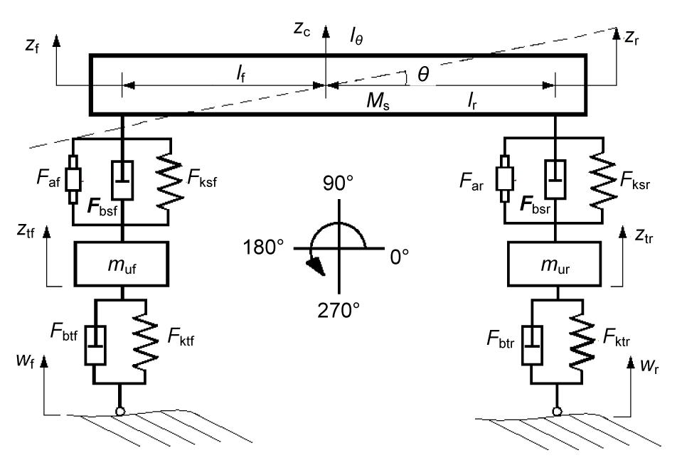
Fig. 1 illustrates a schematic of a half-car AVSS physical model, of sprung mass Ms, pitch moment of inertia Iθ, pitch angular displacement θ, and front and rear unsprung masses muf and mur, respectively. zc, ztf, and ztr are the vertical displacements of the sprung mass at the centre of gravity, the front tyre, and the rear tyre, respectively. The lengths between the front and rear axles and the vehicle centre of gravity are given by lf and lr, respectively. The front and rear suspensions travel are expressed as yf=ztf−(zc−lfsinθ) and yr=ztr−(zc+lrsinθ), respectively. Fksf and Fksr are the forces due to the front and rear suspension springs, respectively. The forces due to the front and rear suspension dampers are Fbsf and Fbsr, respectively. The front and rear actuator forces are given by Faf and Far, respectively. Fktf and Fktr are the front and rear tyre spring forces, respectively, while the front and rear suspension damping forces are given by Fbtf and Fbtr, respectively.
Fig.1 Schematic of a half-car active vehicle suspension systems (AVSS) model for observing vehicle pitching motion
Application of Newton’s second law of motion to the nonlinear half-car AVSS gives the governing equations of motion in state-space form as (Szaszi et al., 2002; Huang et al., 2010)
,
where x is the state vector, u is the control input vector, w is the disturbance input vector, f(x) is the system vector, g(x) is the control input matrix, and p is the disturbance input matrix.
,
,
,
.
The output equation is given as
.
The components of vector f(x) are given as
,
,
,
,
,
,
,
where vf and vr are the front and rear control input voltages, respectively; and are linear and and are nonlinear spring coefficients for the front and rear suspensions, respectively; while and are linear, and asymmetric, and and nonlinear damping coefficients for the front and rear suspensions, respectively; ktf and ktr are the front and rear tyre stiffnesses, respectively; btf and btr are the front and rear tyre damping coefficients, respectively; and sgn() is the ‘signum’ function.
Eqs. (12)–(15) are the hydraulic actuator dynamics, where Ahyd is the hydraulic piston area, and the pressure drop across the front and rear hydraulic actuator pistons are given by Plf and Plr, respectively; α, β and γ are hydraulic actuator parameters, τ is the hydraulic actuator time constant, and Kvf and Kvr are the servo valve gains for the front and rear actuators, respectively. The front and rear servo valve displacements are given by xvf and xvr, respectively.
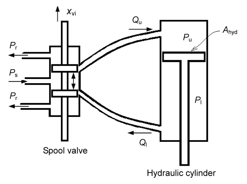
A three-land four-way spool-valve double-acting hydraulic actuator (Fig. 2), was used in the AVSS. In Fig. 2, Qu and Ql are the hydraulic fluid flow rates to the upper and lower portions of the hydraulic cylinder, respectively, Ps is the supply pressure, Pr is the return pressure, and Pu and Pl are the hydraulic fluid pressures in the upper and lower portions of the cylinder, respectively.
Fig.2 Diagram of a double-acting hydraulic actuator
The control input matrix, g(x), is given as
.
The disturbance input matrix, p, is given as
.
2.2. Road input disturbance modelling
Eqs. (18) and (19) express the front and rear wheel input disturbances, wf and wr, respectively. The sinusoidal bump profile is illustrated in Fig. 3.
where a is the bump amplitude, V is the vehicle forward velocity, λ is the disturbance wavelength, t is the simulation time, and subscripts f and r denote the front and rear suspensions, respectively. tr0=1+td, where td is the time delay between the front and rear wheels,
.
The half-car, hydraulic actuator, and road input disturbance model parameters are given in Table 1 (Weber and Braaksma, 2000; Szaszi et al., 2002; Du and Zhang, 2009a).
The performance specifications used in this work are:
The closed-loops should be nominally stable, and the controller must have good command following and disturbance rejection.
The maximum allowable suspension travel, zmax, should not exceed the limit given as
,
where i∈(f, r), and zmax is set to ±0.08 m.
The maximum allowable control voltage, umax, is expressed as
,
where umax is equal to ±10 V.
The maximum allowable controlled force, Fai, is given as
,
where g is the acceleration due to gravity, equal to 9.81 m/s2.
To maintain good road holding, the dynamic tyre load, Fti, should not exceed the static load, (Gao et al., 2006),
,
where
,
and
.
The root mean square (RMS) values of performance parameters given by , will be used to enable detailed performance comparison of the AVSS with the PVSS. For n simulation samples:
,
where
.
ISO 2631-1:1997 frequency weighted RMS acceleration is the basis for evaluation of vehicle ride comfort. The AVSS model does not include vehicle seats, thus Wk, the ISO 2631-1:1997 frequency weighting for acceleration input at the feet, was selected. A fifth order approximation of Wk is expressed as (Zuo and Nayfeh, 2003):
.
The weighted RMS acceleration, , for n samples is given by
,
where the axis multiplication factor kaxis=0.40, for vertical sprung mass acceleration along the z axis. A vibration-induced discomfort scale for various values of is given by the ISO 2631-1:1997 (Griffin, 2007).
4. Controller design
4.1. Control architecture
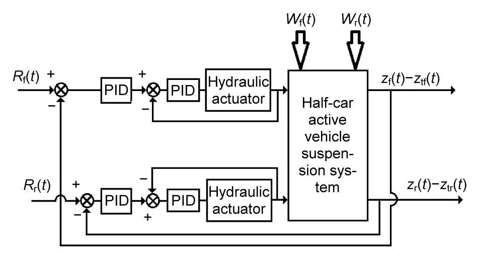
The control architecture (Fig. 4) consists of two control loops: the outer control loop serves to control suspension travel, while the inner PID force control loop ensures that the desired control force is achieved by the hydraulic actuator. Rf(t) and Rr(t) are the front and rear suspension travel reference signals, respectively.
Fig.4 Control architecture
4.2. PID suspension travel control loop design
The structure of the PID controller structure has been applied widely (Gao, 2002; Astrom and Hagglund, 2004; Hanafi, 2010). To perform suspension travel regulation, the suspension travel reference signal, Ri is set to zero so that the error between the reference and the suspension travel tends to zero as t→∞ (Gao, 2002). The outer PID suspension travel loop generates the desired actuator force reference signal Fairef, given in Eq. (31).
,
,
where KP is the proportional gain, KI is the integral gain, KD is the derivative gain, subscript i represents either the front or rear suspension, i∈(f, r), and ei is the error signal. The PID controller gains for the suspension travel loop are listed in Table 2. These gains were obtained by applying the Ziegler-Nichols PID controller gains tuning method.
Table 2
PID suspension travel control loop tuning parameters
Suspension
PID gains
KP
KI
KD
Front
0.000 75
0.0375
0.000 187 5
Rear
0.000 60
0.0300
0.000 150 0
4.3. PID force control loop design
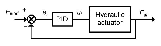
The PID force control loop is shown in Fig. 5 in which ui is the hydraulic actuator control voltage.
Fig.5 Inner PID force feedback control loop
This control input signal is generated by minimizing ei, the error between Fairef and the actual actuator force Fai given in Eq. (33):
,
and ui is then calculated using PID control (Gao, 2002; Astrom and Hagglund, 2004; Hanafi, 2010):
.
A saturation block was placed in front of the controller output to ensure that the control voltage limits (|ui(t)|≤10 V) were not exceeded in the MATLAB/Simulink implementation. The PID controller gains for the inner force control loop are listed in Table 3. These controller gains were also obtained using the Ziegler-Nichols PID controller tuning rules.
Table 3
PID force control loop tuning parameters
Suspension
PID gains
KP
KI
KD
Front
0.001
0.0145
0.0003
Rear
0.001
0.0140
0.0003
5. Simulation results and discussion
The half-car AVSS and PVSS models were built in the MATLAB/Simulink environment. The ordinary differential equation (ODE)-3 (Bogacki-Shampine) fixed step solver was selected for the simulations. To enable observation of all model dynamics, the sampling time was set to Ts=0.0001 s, smaller in magnitude than the fastest half-car AVSS model dynamics (Dahunsi and Pedro, 2010). Since the AVSS and PVSS models do not have multiple sampling times, the tasking mode for periodic sampling times was set to “Single Tasking”.
A chirp road input disturbance signal of amplitude ±15 mm (Sammier et al., 2003) with frequency increasing from 0–100 Hz (over a simulation period of 100 s), was applied to perform a frequency sweep on the AVSS and PVSS (Savaresi et al., 2010). Spectral analysis was performed on the AVSS and PVSS model outputs with the MATLAB Welch algorithm/spectral estimator. Optimal frequency response plots were obtained by using the “Hamming” window setting, a segment length of N/100 (where N is the total number of samples) and a percentage overlap of 214 (The MathWorks, Inc., 2001).
Frequency responses are plotted for Δ=±30% variation in the linear, nonlinear, and asymmetric damping coefficients in Section 5.1 (Chen et al., 2005). The time domain response plots for the AVSS and PVSS traversing over a sinusoidal bump road input disturbance are given in Section 5.2 for ±30% variation in , respectively (Chen et al., 2005).
5.1. Variation of suspension damping coefficients in the frequency domain
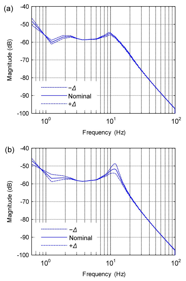
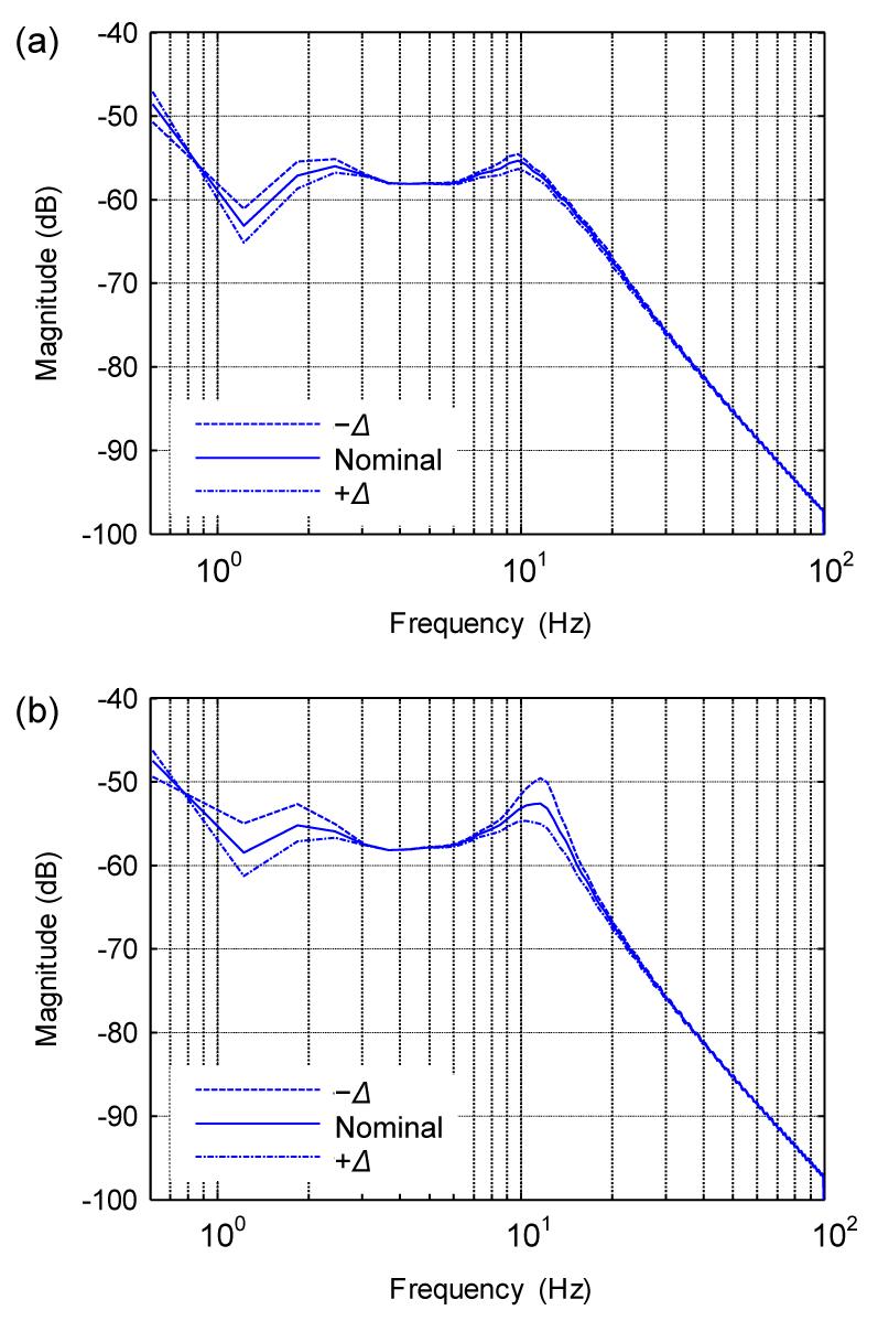
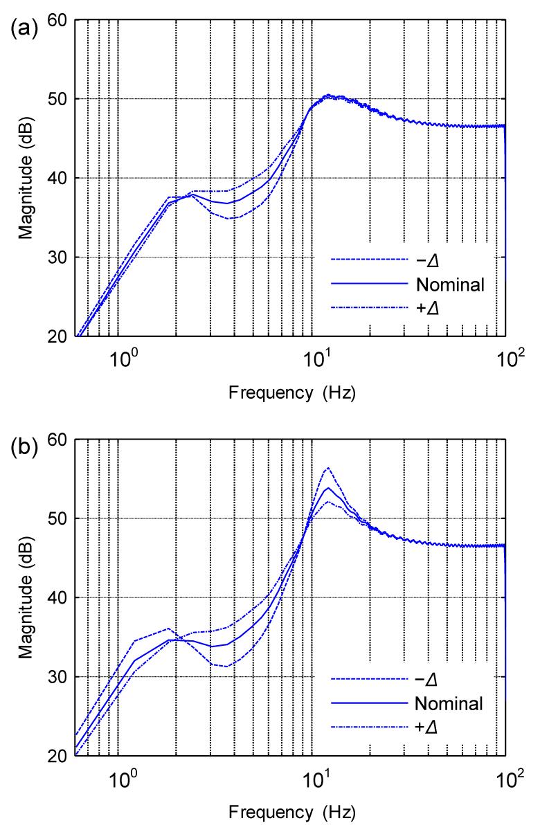
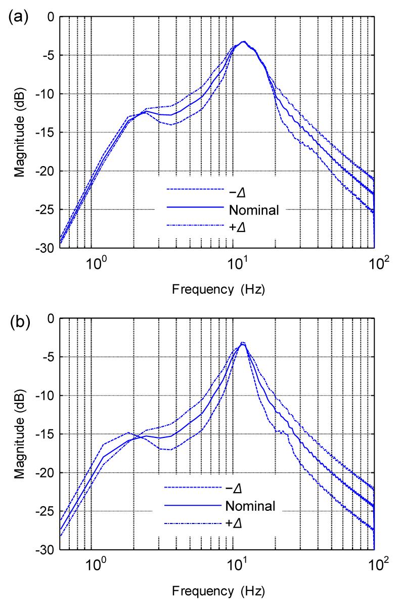
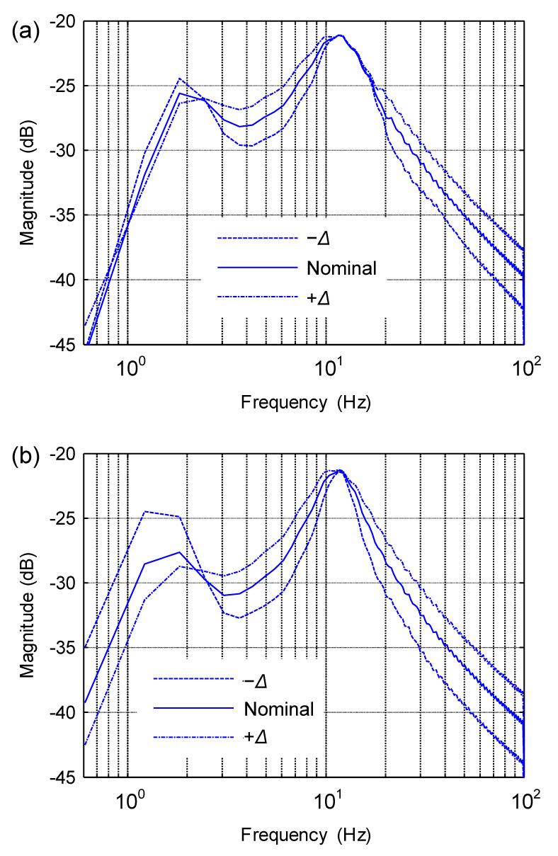
Figs. 6–11 show the AVSS and PVSS front suspension travel, rear suspension travel, front dynamic tyre force, rear dynamic tyre force, sprung mass acceleration, and pitch angular acceleration power spectral density (PSD) plots, respectively, for Δ=±30% variation in , , and about their nominal values. The AVSS response was more robust to variation in suspension damping coefficients in the region below 4 Hz and the region around the wheel-hop frequency (≈12 Hz), than that of the PVSS. The PVSS peak at the wheel-hop frequency was higher than that of the AVSS. Between 4–8 Hz and above 20 Hz, both the AVSS and PVSS produced similar performance.
Fig.6 Front suspension travel PSD for AVSS (a) and PVSS (b)
Fig.7 Rear suspension travel PSD for AVSS (a) and PVSS (b)
Fig.8 Front dynamic tyre force PSD for AVSS (a) and PVSS (b)
Fig.9 Rear dynamic tyre force PSD for AVSS (a) and PVSS (b)
Fig.10 Sprung mass acceleration PSD for AVSS (a) and PVSS (b)
Fig.11 Pitch angular acceleration PSD for AVSS (a) and PVSS (b)
5.2. Variation of suspension damping coefficients: time domain example
Table 4 (p.410) shows the RMS values obtained as the AVSS and PVSS traversed the sinusoidal bump road input disturbance given in Section 2.2 for Δ=±30% variation in , , and about their nominal values.
FST: front suspension travel; RST: rear suspension travel; SMA: sprung mass acceleration; PAA: pitch angular acceleration
The AVSS and PVSS front suspension travel time histories are shown in Figs. 12a and 12b, respectively. The AVSS was more robust than the PVSS in response to variation in suspension damping coefficients. The figures also show that the AVSS front suspension travel minimum and maximum peak values were considerably lower than those of the PVSS. The RMS front suspension travel performance of the AVSS was considerably better than that of the PVSS, although the AVSS performance deteriorated with increasing suspension damping (Table 4). The AVSS and PVSS did not exceed the ±0.08 m suspension travel limit set in Section 3.
Fig.12 Front suspension travel time history for AVSS (a) and PVSS (b)
Figs. 13a and 13b show the rear suspension travel time histories for the AVSS and PVSS, respectively. The peak rear suspension travel values were lower for the AVSS than for the PVSS. The AVSS performance in terms of reducing RMS suspension travel varied between 33.00% at minimum suspension damping and 28.77% at maximum suspension damping. Thus, there was a drop in performance as the suspension damping increased. The ±0.08 m suspension travel limit set in Section 3 was not exceeded by either the AVSS or the PVSS.
Fig.13 Rear suspension travel time history for AVSS (a) and PVSS (b)
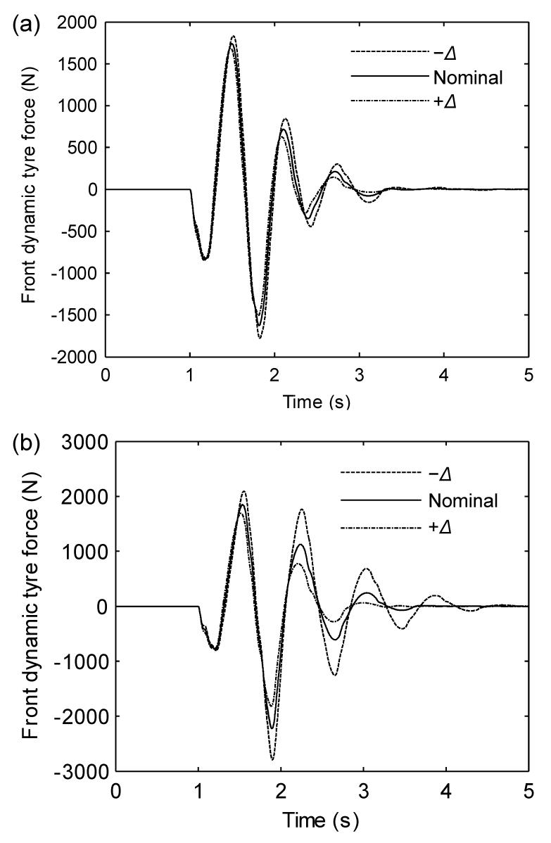
The front dynamic tyre force time histories for the AVSS and PVSS are shown in Figs. 14a and 14b, respectively. The AVSS front dynamic tyre force was more robust to variation in the suspension damping coefficients than the PVSS. These figures also show that the AVSS produced lower peak front dynamic tyre force magnitudes than the PVSS. Furthermore, the peak front dynamic tyre forces for both the AVSS and PVSS did not exceed the front dynamic tyre force limits specified in Section 3. The AVSS performance, in terms of reducing RMS front dynamic tyre force, deteriorated with increasing suspension damping compared with PVSS performance (Table 4).
Fig.14 Front dynamic tyre force time history for AVSS (a) and PVSS (b)
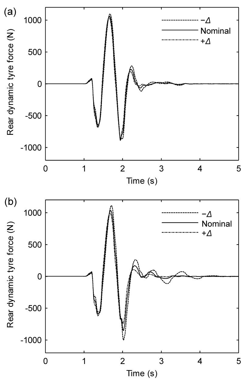
Figs. 15a and 15b show the rear dynamic tyre force time histories for the AVSS and PVSS, respectively. The AVSS rear dynamic tyre force was less sensitive to variation in the suspension damping, than the PVSS. The AVSS peak rear dynamic tyre forces were lower than those of the PVSS. In addition, the rear dynamic tyre force limits specified in Section 3 were not exceeded by either the AVSS or the PVSS. Table 4 shows that the PVSS RMS rear dynamic tyre force was lower than that of the AVSS. However, the AVSS performance improved with increasing suspension damping.
Fig.15 Rear dynamic tyre force time history for AVSS (a) and PVSS (b)
Figs. 16a and 16b show the sprung mass acceleration time histories for the AVSS and PVSS, respectively. The AVSS attenuated the sprung mass acceleration oscillation about 1.5 s faster than the PVSS, at the minimum suspension damping (Δ=−30%). The AVSS peak sprung mass acceleration values were lower than those of the PVSS. The AVSS reduced the ISO-weighted RMS acceleration compared with the PVSS. However, Table 5 shows that the AVSS performance degraded with increasing suspension damping (from 31.81% improvement at the minimum damping, to 15.61% improvement at the maximum damping). Table 5 also shows that the AVSS and PVSS obtained acceleration values within the ISO 2631-1:1997 range for the “Not uncomfortable” level of discomfort.
Fig.16 Sprung mass acceleration time history for AVSS (a) and PVSS (b)
Table 5
Weighted RMS acceleration,
\documentclass[12pt]{minimal} \usepackage{amsmath}
\usepackage{wasysym} \usepackage{amsfonts} \usepackage{amssymb}
\usepackage{amsbsy} \usepackage{mathrsfs}
\setlength{\oddsidemargin}{-69pt}
\begin{document}
\[a_{wi}^{RMS}\]
\end{document} and discomfort levels for the PVSS and AVSS
Condition
(m/s2)
Reduction by AVSS
ISO 2631-1 level of discomfort
PVSS
AVSS
−Δ
0.2757
0.1880
31.81%
Not uncomfortable
Nominal
0.2205
0.1712
22.36%
+Δ
0.1890
0.1595
15.61%
Figs. 17a and 17b show the pitch angular acceleration time histories for the AVSS and PVSS, respectively. The AVSS was more robust in response to variation in suspension damping coefficients than the PVSS. The AVSS attenuated the pitch angular acceleration oscillation about 1 s faster than the PVSS for Δ=−30%. However, the AVSS peak pitch angular acceleration values were higher than the corresponding PVSS values. The percentage reduction in RMS pitch angular acceleration by the AVSS compared with the PVSS deteriorated with increasing suspension stiffness; from 20.76% at Δ=−30% to −5.39% at Δ=30% (Table 4).
Fig.17 Pitch angular acceleration time history for AVSS (a) and PVSS (b)
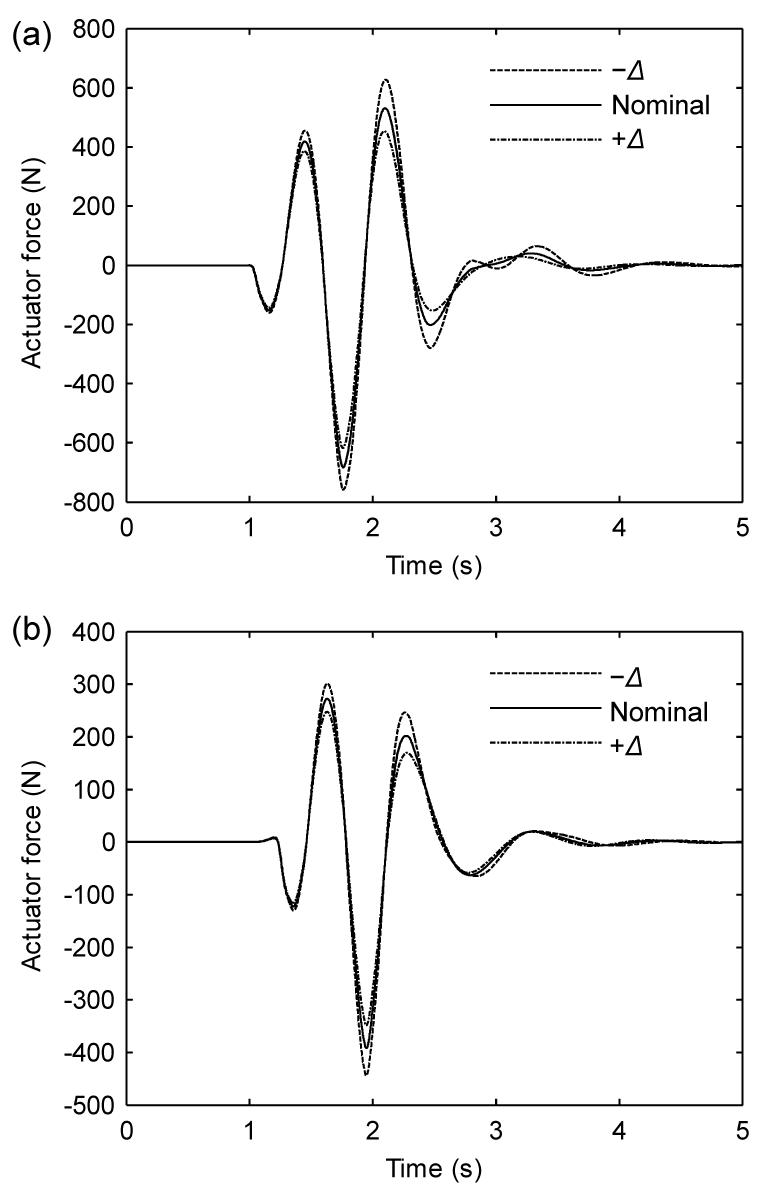
Figs. 18a and 18b show the actuator force time histories for the front and rear suspension actuators, respectively. The AVSS maintained peak actuator force levels much lower than the limits specified in Section 3 for the duration of the simulation. The RMS actuator forces for the front and rear suspension actuators reduced with increasing suspension damping (Table 4).
Fig.18 Actuator force time history for AVSS (a) and PVSS (b)
5.3. Effect of the inner force control loop on AVSS performance
In this section, the effect of the inner force control loop on AVSS performance is investigated. An AVSS with both an inner PID force control loop and an outer PID suspension travel control loop was compared with a second AVSS without the inner force control loop. The PID controller gains of the outer suspension travel for the second AVSS remained the same as those given in Table 2. The sprung mass acceleration frequency and time domain responses of an AVSS without the PID force control loop are plotted against those of an AVSS with the PID force control loop. Only nominal suspension damping was considered.
Fig. 19a shows that the AVSS with PID force control performed better than the AVSS without PID force control over the frequency range plotted. Fig. 19b shows that the AVSS with force control was able to attenuate the sprung mass oscillation due to the road input disturbance after about 2 s. The AVSS without force control was unable to stabilize the hydraulic actuator, therefore the sprung mass oscillation continued beyond the duration of the simulation.
Fig.19 Comparison of AVSS sprung mass acceleration response with and without force control (a) PSD; (b) Time history
6. Conclusions
This paper described the development of controllers for a nonlinear half-car AVSS with hydraulic actuator dynamics, by application of PID-based controls, an outer PID suspension travel control loop, and an inner PID force control loop. A nonlinear half-car PVSS was developed for performance comparisons.
Performance specifications were outlined for controller performance, physical constraints (control input voltage, hydraulic actuator force output and suspension travel limitations), road holding (to prevent tyre lift off), and ride comfort (based on ISO 2631-1:1997).
Results of performance comparisons between the AVSS with the PVSS in the presence of uncertainties due to variations in suspension damping were given based on frequency domain analysis and an example in the time domain.
In the frequency domain analysis, a frequency sweep was used to obtain frequency response data from the various outputs of the nonlinear AVSS and PVSS models.
The frequency domain results indicated that the AVSS was less sensitive than the PVSS to variation in suspension damping in the low frequency regions (<4 Hz), between 4–8 Hz, and around the wheel-hop frequency for all the model outputs.
Above 20 Hz, both the AVSS and PVSS frequency responses to uncertainties in damping were similar.
Time domain results confirm the robustness of the AVSS in the presence of uncertainties in damping, in the low frequency region.
The AVSS provided a better compromise between vehicle ride comfort and road holding than the PVSS, without exceeding suspension travel, control input voltage, and hydraulic actuator force output constraints.
The need for hydraulic actuator force control to stabilize the actuator, thus enhancing AVSS performance, was demonstrated.
References
[1] Akcay, H., Turkay, S., 2009. Influence of tire damping on mixed H2/H∞ synthesis of half-car active suspensions. Journal of Sound and Vibration, 322(1-2):15-28.
[2] Astrom, K.J., Hagglund, T., 2001. The future of PID control. Control Engineering Practice, 9(11):1163-1175.
[3] Astrom, K.J., Hagglund, T., 2004. Revisiting the Ziegler-Nichols step response method for PID control. Journal of Process Control, 14(6):635-650.
[4] Buckner, G.D., Schuetze, K.T., Beno, J.H., 2000. Active Vehicle Suspension Control Using Intelligent Feedback Linearization. Proceedings of the American Control Conference, 6:4014-4018.
[5] Cetin, S., Akkaya, A.V., 2010. Simulation and hybrid fuzzy-PID control for positioning of a hydraulic system. Nonlinear Dynamics, 61:465-476.
[6] Chantranuwathana, S., Peng, H., 2004. Adaptive robust force control for vehicle active suspension. International Journal of Adaptive Control and Signal Processing, 18(2):83-102.
[7] Chen, H., Liu, Z.Y., Sun, P.Y., 2005. Application of constrained H∞ control to active suspension systems on half-car models. Journal of Dynamic Systems, Measurement and Control, Transactions of the ASME, 127(3):345-354.
[8] Chien, T.L., Chen, C.C., Chiu, H.C., Cheng, H.W., Chen, Y.C., 2008. Almost disturbance decoupling control of nonlinear MIMO uncertain system and application to half-car active suspension system. International Journal of Vehicle Design, 46(4):367-392.
[9] Dahunsi, O.A., Pedro, J.O., 2010. Neural network-based identification and approximate predictive control of a servo-hydraulic vehicle suspension system. Engineering Letters, 18(4):357-368.
[10] Dahunsi, O.A., Pedro, J.O., Nyandoro, O.T., 2009. Neural Network-based Model Predictive Control of a Servo-hydraulic Vehicle Suspension System. , Proceedings of the International IEEE Africon, 1-6. :1-6.
[11] Dahunsi, O.A., Pedro, J.O., Nyandoro, O.T., 2010. System identification and neural network based PID control of servo-hydraulic vehicle suspension system. SAIEE Africa Research Journal, 101(3):93-105.
[12] Du, H., Zhang, N., 2007.
H∞ control of active vehicle suspensions with actuator time delay. Journal of Sound and Vibration, 301(1-2):236-252.
[13] Du, H., Zhang, N., 2009. Fuzzy control for nonlinear uncertain electrohydraulic active suspensions with input constraint. IEEE Transactions on Fuzzy Systems, 17(2):343-356.
[14] Du, H., Zhang, N., 2009. Static output feedback control for electrohydraulic active suspensions via T-S fuzzy model approach. Journal of Dynamic Systems, Measurement and Control, Transactions of ASME, 131(5):1-11.
[15] Du, H., Zhang, N., 2010. Robust active suspension design subject to vehicle inertial parameter variations. International Journal of Automation and Computing, 7(4):419-427.
[16] Ekoru, J.E.D., Dahunsi, O.A., Pedro, J.O., 2011. PID Control of a Nonlinear Half-car Active Suspension System via Force Feedback. , Proceedings of the International IEEE Africon, 1-6. :1-6.
[17] Eski, I., Yildirim, S., 2009. Vibration control of vehicle active suspension system using a new robust neural network control system. Simulation Modelling Practice and Theory, 17(5):778-793.
[18] Fateh, M.M., Alavi, S.S., 2009. Impedance control of an active suspension system. Mechatronics, 19(1):134-140.
[19] Feng, J.Z., Li, J., Yu, F., 2003. GA-based PID and fuzzy logic control for active vehicle suspension system. International Journal of Automotive Technology, 4(4):181-191.
[20] Fialho, I., Balas, G.J., 2002. Road adaptive active suspension using linear parameter-varying gain-scheduling. IEEE Transactions on Control Systems Technology, 10(1):43-54.
[21] Fischer, D., Isermann, R., 2004. Mechatronic semi-active and active vehicle suspensions. Control Engineering Practice, 12(11):1353-1367.
[22] Gao, H., Lam, J., Wang, C., 2006. Multi-objective control of vehicle active suspension systems via load-dependent controllers. Journal of Sound and Vibration, 290(3-5):654-675.
[23] Gao, Z., 2002. From linear to nonlinear control means: a practical progression. ISA Transactions, 41(2):177-189.
[24] Griffin, M.J., 2007. Discomfort from feeling vehicle vibration. Vehicle System Dynamics, 45(7-8):679-698.
[25] Guclu, R., 2003. Active control of seat vibrations of a vehicle model using various suspension alternatives. Turkish Journal of Engineering and Environmental Sciences, 27(6):361-373.
[26] Guglielmino, E., Edge, K.A., 2004. A controlled friction damper for vehicle applications. Control Engineering Practice, 12(4):431-443.
[27] Guo, B., Liu, H., Luo, Z., 2009. Adaptive PID Controller Based on BP Neural Network. , Proceedings of the International Conference on Artificial Intelligence, 148-150. :148-150.
[28] Hanafi, D., 2010. PID Controller Design for Semi-active Car Suspension based on Model from Intelligent System Identification. , Proceedings of the 2nd International Conference on Computer Engineering and Applications, 60-63. :60-63.
[29] Hassanzadeh, I., Alizadeh, G., Shirjoposht, N.P., Hashemzadeh, F., 2010. A new optimal nonlinear approach to half car active suspension. IACSIT International Journal of Engineering and Technology, 2(1):78-84.
[30] Hrovat, D., 1997. Survey of advanced suspension developments and related optimal control applications. Automatica, 33(10):1781-1817.
[31] Huang, C.J., Lin, J.S., Chen, C.C., 2010. Road adaptive algorithm design of half-car active suspension system. Expert Systems with Applications, 37(6):4392-4402.
[32] Ji, X.D., Wan, K.J., Hai, N.Y., 2007. Time Delay Force Control for Vehicle Active Suspension System. , Proceedings of the 26th Chinese Controls Conference, 640-645. :640-645.
[33] Ji, X.J., Li, S.J., 2009. Design of the Fuzzy-PID Controller for New Vehicle Active Suspension with Electro-Hydrostatic Actuator. , Proceedings of the 4th IEEE Conference on Industrial Electronics and Applications, 60-63. :60-63.
[34] Kumar, M.S., 2008. Development of an Active Suspension System for Automobiles using PID Controller. , Proceedings on the World Congress on Engineering, 1472-1477. :1472-1477.
[35] Marusak, P.M., Kuntanapreeda, S., 2011. Constrained model predictive force control of an electrohydraulic actuator. Control Engineering Practice, 19(1):62-73.
[36] ODwyer, A., 2006. Handbook of PI an PID Controller Tuning Rules. Imperial College Press,London :
[37] Pedro, J.O., 2007.
H2-LQG/LTR controller design for active suspension systems. R and D Journal of the South African Institution of Mechanical Engineering, 23(2):32-41.
[38] Pedro, J.O., Dahunsi, O., 2011. Neural network based feedback linearization control of a servo-hydraulic vehicle suspension system. International Journal of Applied Mathematics and Computer Science, 21(1):137-147.
[39] Priyandoko, G., Mailah, M., Jamaluddin, H., 2009. Vehicle suspension system using skyhook adaptive neuro active force control. Mechanical Systems and Signal Processing, 23(3):855-868.
[40] Renn, J., Wu, T., 2007. Modelling and control of a new 1/4t servo-hydraulic vehicle active suspension system. Journal of Marine Science and Technology, 15(3):265-272.
[41] Ryu, S., Kim, Y., Park, Y., 2008. Robust H∞ preview control of an active suspension system with norm-bounded uncertainties. International Journal of Automotive Technology, 9:585-592.
[42] Sam, Y.M., Hudha, K., 2006. Modelling and Force Tracking of Hydraulic Actuator for an Active Suspension System. , Proceedings of the IEEE Conference on Industrial Electronics and Applications, 1-6. :1-6.
[43] Sammier, D., Sename, O., Dugard, L., 2003. Skyhook and H∞ control of semi-active suspensions: some practical aspects. Vehicle System Dynamics, 39(4):279-308.
[44] Savaresi, S.M., Poussot-Vassal, C., Spelta, C., 2010. Semi-active Suspension Control Design for Vehicles. Butterworth-Heinemann,Boston :
[45] Szaszi, I., Gaspar, P., Bokor, J., 2002. Nonlinear Active Suspension Modelling using Linear Parameter Varying Approach. , Proceedings of the 10th Mediterranean Conference on Control and Automation, 1-10. :1-10.
[46] The MathWorks, Inc., 2001. Signal Processing Toolbox for Use with Matlab® User’s Guide Version 5.1. , :
[47] Weber, P.A., Braaksma, J.P., 2000. Towards a North American geometric design standard for speed humps. ITE Journal, 70(1):30-34.
[48] Williams, R.A., 1997. Automotive active suspensions Part 2: Practical considerations. Proceedings of the Institution of Mechanical Engineers, Part D: Journal of Automobile Engineering, 211(6):427-444.
[49] Yagiz, N., Hacioglu, Y., 2008. Backstepping control of a vehicle with active suspensions. Control Engineering Practice, 16(12):1457-1467.
[50] Yoshimura, T., Kume, A., Kurimoto, M., Hino, J., 2001. Construction of an active suspension system of a quarter car model using the concept of sliding mode control. Journal of Sound and Vibration, 239(2):187-199.
[51] Zhao, Q., Yin, J., Li, D., 2011. Intelligent Compound Control of Vehicle Active Suspension based on RBF Neural Network. Proceedings of the 3rd International Conference on Measuring Technology and Mechatronics Automation, 2:441-444.
[52] Zuo, L., Nayfeh, S.A., 2003. Low order continuous-time filters for approximation of the ISO 2631-1 human vibration sensitivity weightings. Journal of Sound and Vibration, 265(2):459-465.
Open peer comments: Debate/Discuss/Question/Opinion


Open peer comments: Debate/Discuss/Question/Opinion
<1>