Tian Li, Ji-ye Zhang, Wei-hua Zhang. A numerical approach to the interaction between airflow and a high-speed train subjected to crosswind[J]. Journal of Zhejiang University Science A, 2013, 14(7): 482-493.
@article{title="A numerical approach to the interaction between airflow and a high-speed train subjected to crosswind", author="Tian Li, Ji-ye Zhang, Wei-hua Zhang", journal="Journal of Zhejiang University Science A", volume="14", number="7", pages="482-493", year="2013", publisher="Zhejiang University Press & Springer", doi="10.1631/jzus.A1300035" }
%0 Journal Article %T A numerical approach to the interaction between airflow and a high-speed train subjected to crosswind %A Tian Li %A Ji-ye Zhang %A Wei-hua Zhang %J Journal of Zhejiang University SCIENCE A %V 14 %N 7 %P 482-493 %@ 1673-565X %D 2013 %I Zhejiang University Press & Springer %DOI 10.1631/jzus.A1300035
TY - JOUR T1 - A numerical approach to the interaction between airflow and a high-speed train subjected to crosswind A1 - Tian Li A1 - Ji-ye Zhang A1 - Wei-hua Zhang J0 - Journal of Zhejiang University Science A VL - 14 IS - 7 SP - 482 EP - 493 %@ 1673-565X Y1 - 2013 PB - Zhejiang University Press & Springer ER - DOI - 10.1631/jzus.A1300035
Abstract: Aerodynamic forces and dynamic performances of railway vehicles are coupled and affected by each other. On the one hand, aerodynamic forces change the displacements of a train. On the other hand, displacements affect aerodynamic forces. Based on vehicle-track coupling dynamics and aerodynamics, a numerical approach to the interaction between airflow and a high-speed train is presented in this paper. Aerodynamic forces and dynamic performances of a high-speed train subjected to crosswind were numerically simulated. Results showed that the interaction between airflow and a high-speed train has a significant influence on displacements and aerodynamic forces of the head coach. Therefore, it is necessary to consider the interaction between airflow and a high-speed train subjected to crosswind.
Darkslateblue:Affiliate; Royal Blue:Author; Turquoise:Article
Article Content
1. Introduction
The crosswind stability of railway vehicles has been studied for several decades, motivated by overturning accidents (Cheli et al., 2010; Li et al., 2011a). Most studies on crosswind stability have focused on aerodynamic issues.
Aerodynamics of railway vehicles subjected to crosswind can be investigated by experiments in wind tunnels and numerical simulations. Wind tunnel experiments have played an important role in determining the aerodynamic characteristics of trains for years. In (Orellano et al., 2006), experimental results for aerodynamic forces were reported, and comparisons were made with regard to different levels of geometric complexity addressing the issues of bogies and spoilers. There was only a small effect for the coefficients, which contributed most to overturning, i.e., the roll moment and the side force. Cheli et al. (2010) presented a numerical experimental procedure for the aerodynamic optimization of AnsaldoBreda EMUV250. Wind tunnel experiments (Suzuki et al., 2003; Bocciolone et al., 2008) were performed to evaluate the aerodynamic characteristics of railway vehicles on typical infrastructures, such as bridges and embankments. To date, the only full-scale experiments were performed on a coastal site at Eskmeals in Cumbria (northwest England) (Baker et al., 2004). Thorough reviews were given by Baker (1991).
In addition, several numerical simulations of aerodynamic characteristics of railway vehicles subjected to crosswind were performed. The unsteady aerodynamic forces of a high-speed train were analyzed in a variety of unsteady crosswinds (Xu and Ding, 2006; Baker, 2010; Thomas et al., 2010; Baker et al., 2011; Shao et al., 2011). A 3D source/vortex panel method (Chiu, 1995) was developed to predict the aerodynamic loads on an idealized railway train model in crosswind at large yaw angles. Numerical results of the airflow passing a simplified train under different yawing conditions were summarized (Khier et al., 2000). Diedrichs (2003) and Diedrichs et al. (2007) discussed the aerodynamic characteristics of the airflow passing a train and found that the 6-m high embankments reduced the permissible crosswind velocity by approximately 20%. Moreover, numerical simulations were carried out using the commercial code FLUENT or STAR-CD (Diedrichs et al., 2007; Cheli et al., 2010).
The dynamic response of a railway vehicle subjected to crosswind was calculated using a vehicle model. Baker (1991) and Ding et al. (2008) used the simple vehicle models to evaluate the running safety against crosswind. In fact, the vehicle and track subsystems were coupled through wheel/rail interaction (Zhai et al., 1996). A detailed vehicle-track coupling model was established for the first time (Zhai et al., 1996); the model has been widely applied.
The crosswind stability in the aforementioned studies was evaluated using an off-line simulation method. Firstly, aerodynamic forces of a train subjected to crosswind were calculated by computational fluid dynamics (CFD), and then, the dynamic response of the train subjected to crosswind was simulated using a vehicle or vehicle-track model. The influence on the aerodynamic forces of displacements was neglected using the off-line simulation. In fact, aerodynamic forces and dynamic performances of railway vehicles were coupled. On the one hand, the aerodynamic forces change the displacements of the train. On the other hand, the displacements affect the aerodynamic forces. To date, there has been no research to simulate the interaction between airflow and a high-speed train.
In this paper, a numerical approach to the interaction between airflow and a high-speed train was presented. The vehicle-track coupling model was adopted to calculate the dynamic response of the train subjected to crosswind. Dynamic performances of a high-speed train subjected to crosswind were discussed in detail.
2. Governing equations
2.1. Equations of fluid dynamics
The flow field around a train subjected to crosswind can be considered as a 3D incompressible viscous turbulent flow. To describe the flow field around the train, a k-ε turbulence model is adopted. The equations of the standard k-ε two-equation model are written as
,
where V is an arbitrary control volume, A is the surface of the volume V, t is the time, ρ is the air density, u is the velocity vector of the flow, is the velocity vector of the surface A, φ is the vector of fluxes, n is the normal direction vector of the surface A, S is the source term, and Γ is the generalized diffusion coefficient. The vector φ includes the flow velocity ui, the turbulent kinematics energy k, and turbulent dissipation ε.
2.2. Equations of vehicle-track coupling dynamics
Vehicle-track coupling dynamics mainly consist of vehicle dynamics, track dynamics, and wheel-rail interaction.
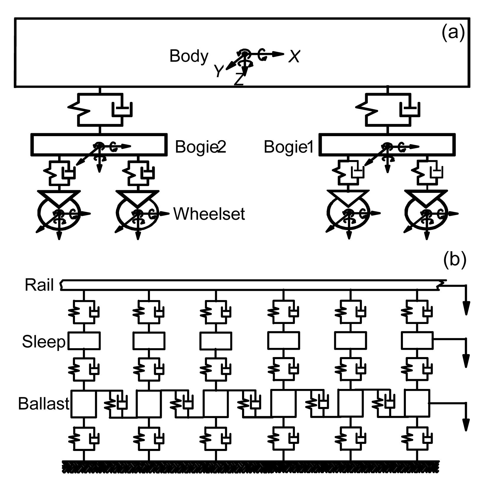
A four-axle railway vehicle with two suspension systems, which is a common railway vehicle used in China, was chosen in this study. The vehicle shown in Fig. 1a consists of a carbody, two bogies, four wheelsets, and two suspension systems. The carbody, bogies, and wheelsets are regarded as rigid components, and their elastic deformations are neglected. Every rigid component is assigned five degrees of freedom: the vertical displacement, the lateral displacement, the roll displacement, the yaw displacement, and the pitch displacement with respect to its mass center.
Fig.1 Vehicle-track coupling system (a) Vehicle system; (b) Track system
The track subsystem shown in Fig. 1b is modeled as an infinite Euler beam, which is supported on a discrete-elastic foundation consisting of three layers. The sleeper is assigned three degrees of freedom: the vertical displacement, the lateral displacement, and the roll displacement. To account for the shearing continuity of the particles between the adjacent ballasts, linear springs and dampers are introduced to model the shear coupling effects. Moreover, the ballasts are assigned only one degree of freedom: the vertical displacement.
Wheel-rail interaction involves two basic issues: the geometric relationship and the contact forces. The Hertz contact theory is used to solve the vertical normal forces. The creep forces are calculated using the Shen-Hedrick-Elkins theory. More detailed descriptions of the normal and creep forces can be found in (Zhai et al., 1996). In this study, rail irregularities are measured from high-speed railways in China.
The equation of the vehicle-track dynamics (Zhai et al., 1996) is written as
,
where M, C, and K are the mass, damping, and stiffness matrices of the vehicle-track system, respectively. X, , and are the generalized displacement, velocity, and acceleration vectors of the system, respectively. F is the generalized force vector including wheel rail contact forces and aerodynamic forces.
3. Numerical approach to the interaction
3.1. Vehicle-track dynamics solution technique
The equations of vehicle-track dynamics were solved using the Zhai method (Zhai et al., 1996). The integral format of the Zhai method is written as
where λ and μ are integral parameters, Δt is the time step and the subscript n denotes the iteration number of the time step.
Substituting Eq. (3) into Eq. (4), can be obtained.
The code for the vehicle-track coupling dynamics was written in the programming language Fortran and verified to be trustworthy (Li et al., 2011a).
3.2. Dynamic mesh technique
Re-mesh and spring analogy methods (Li et al., 2011b) were adopted to renew the mesh of CFD. If the spring analogy method fails to renew the mesh, the re-mesh method is adopted. The spring analogy method is simple but highly efficient. The stiffness of a given edge i-j is defined as Kij=1/rij, where Kij is the stiffness, and rij is the distance between the ith and jth nodes.
The displacements of nodes are obtained:
,
where Ni is the total number of nodes connected to the ith node, and Δrj is the displacements of the jth node.
The new position of the ith node is determined by
.
3.3. Solution strategies
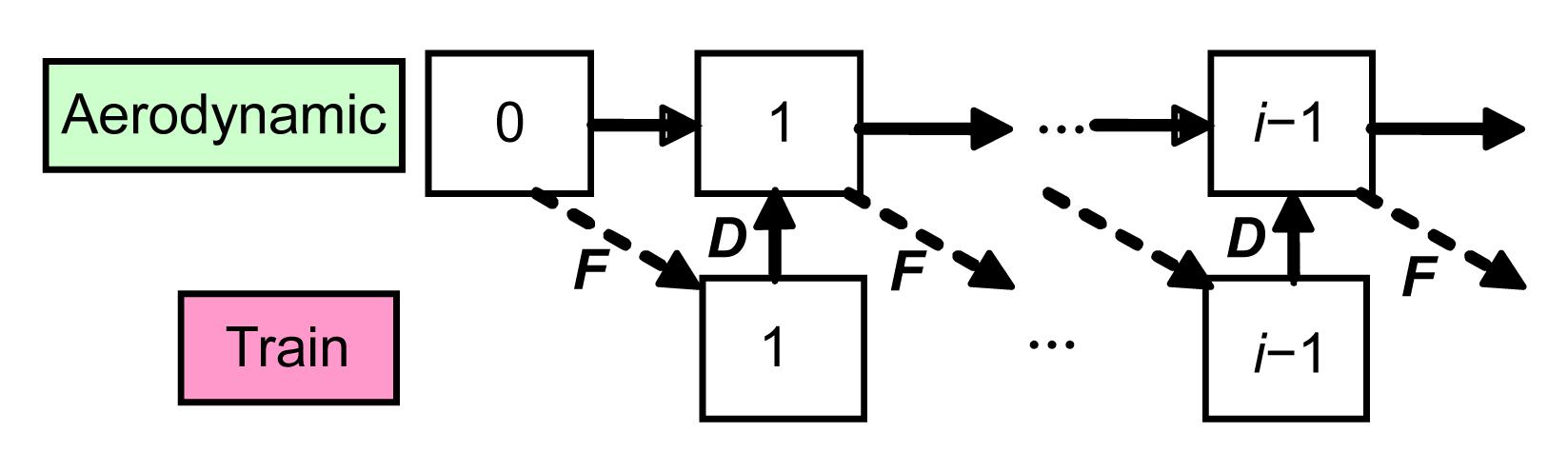
Co-simulation means that aerodynamic forces and dynamic performances of a high-speed train are calculated alternatively; namely, the interaction between airflow and a high-speed train is considered.
Fig. 2 shows a schematic diagram of the numerical approach to the interaction between airflow and a high-speed train. The aerodynamic forces F include the side force, the lift force, the roll moment, the pitch moment, and the yaw moment. The displacements of the train D include the lateral displacement y, the vertical displacement z, the roll displacement θ, the yaw displacement ψ, and the pitch displacement β.
Fig.2 Numerical procedure
Δtf and Δtv represent the time step sizes in the computational fluid dynamics and vehicle-track dynamics, respectively. Generally, the orders of magnitude of Δtf and Δtv are 1.0×10⁻³ s and 1.0×10⁻⁵ s, respectively. As shown in Fig. 2, the procedure for the numerical approach to the interaction between airflow and a high-speed train can be summarized as follows:
Calculate the aerodynamic forces of the train in an initial static status until the forces reach relatively steady values, such as the fluctuation is less than 3%.
Transfer the message of aerodynamic forces to the user-defined-function (UDF), which is an interface of the commercial code FLUENT, and then invoke the code for the vehicle-track coupling dynamics.
Load the above aerodynamic forces onto the vehicle-track model and calculate the dynamic response of the vehicle. The number of time step iterations for the vehicle-track dynamics is Δtf/Δtv.
Transfer the message of displacements to the commercial code FLUENT.
Renew the mesh of CFD using the dynamic mesh technique described in Section 3.2.
Keep solving Eq. (1) and calculate the aerodynamic forces of the train in the above displacements.
Repeat steps 2–6 until the number of time step iterations reaches the expected value.
4. Computational model and domain
A schematic diagram of the computational domain of a high-speed train subjected to crosswind is shown in Fig. 3. The ballast, sleeper, and rails are neglected in the computational fluid dynamics. Unstructured tetrahedral meshes were adopted.
Fig.3 Schematic diagram of computational domain
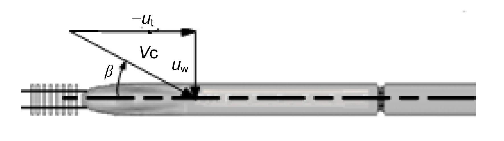
The running speed of the train ut and crosswind velocity uw were specified at the inlet boundary, i.e., uinlet=−ut; vinlet=uw. In addition, traction-free and symmetry conditions were specified at the outlet and top boundaries, respectively. The slip condition was specified at the wall boundary, i.e., uwall=−ut. Although natural wind was turbulent and a boundary layer existed near the ground, the effect of the boundary layer was neglected and a uniform inflow was adopted. The calculation was performed for the high-speed train at ut=350 km/h and subjected to crosswind uw=13.8 m/s. The combined wind velocity was 98.2 m/s and the yaw angle was 8.08°, as shown in Fig. 4.
Fig.4 Schematic diagram of the combined wind velocity β: yaw angle; Vc: combined velocity
Fig. 5 shows a schematic diagram of aerodynamic forces and moments. Aerodynamic forces include the side force Fy, the lift force Fz, the roll moment Mx, the pitch moment My, and the yaw moment Mz. The reference points of the moment of head, middle, and tail coaches are (−13.2, 0.0, 1.72), (−38.2, 0.0, 1.72) and (−63.2, 0.0, 1.72), respectively.
Fig.5 Schematic diagram of aerodynamic forces
In order to describe the flow field around a train and the wall-stress on the train surface, a k-ε turbulence model with a wall function treatment was adopted. The Reynolds averaged Navier-Stokes (RANS) equations were used to simulate the flow field around the train and solved by the finite volume method (FVM). The velocity-pressure coupling was achieved by using the SIMPLE (semi-implicit method for pressure linked equations) scheme. The techniques for solving the fluid dynamics in this study were similar to those in (Diedrichs et al., 2007). Numerical simulations were carried out using the commercial code FLUENT.
Table 1 shows the effect of aerodynamic forces on the maximum mesh sizes of the train surface. It is shown that aerodynamic forces are almost stable when the maximum mesh sizes of head, middle, and tail coaches are 80 mm, 100 mm, and 80 mm, respectively. Therefore, these sizes were chosen.
Table 1
Effect of aerodynamic forces on mesh sizes
Mesh sizes (mm)
Fy (kN)
Fz (kN)
Head
Mid
Tail
Head
Tail
Head
Tail
120
150
120
−49.22
−16.87
4.46
11.97
100
120
100
−48.72
−16.06
5.42
11.30
80
100
80
−47.22
−15.25
6.38
10.83
60
80
60
−46.71
−14.99
6.46
10.63
Table 2 shows the effect of aerodynamic forces on the computational domain including the length L, width W, and height H. For example, the length 75+150 means that the distance between the inlet surface and nose of the head coach is 75 m, and the distance between the outlet surface and the nose of the tail coach is 150 m. The aerodynamic forces are almost stable when the length, width, and length of the domain are 375.4 m, 90 m, and 60 m, respectively. Therefore, that domain was chosen.
Table 2
Effect of aerodynamic forces on domain
Domain (m)
Fy (kN)
Fz (kN)
L
W
H
Head
Tail
Head
Tail
75+150
30+40
30
−48.47
−16.34
7.63
11.97
75+200
30+50
40
−47.35
−15.42
6.52
11.02
100+200
30+60
60
−47.22
−15.25
6.38
10.83
Table 3 shows the effect of aerodynamic forces on turbulent models including standard k-ε, re-normalization group (RNG) k-ε, realizable k-ε, standard k-ω, and shear stress transports (SST) k-ω models. It is shown that the differences between standard k-ε model and the other models are small except the standard k-ω model. Therefore, the standard k-ε model was chosen.
Table 3
Effect of aerodynamic forces on turbulence models
Method
Fy (kN)
Fz (kN)
Head
Mid
Tail
Head
Tail
Standard k-ε
−47.22
−8.62
−15.25
6.38
10.83
RNG k-ε
−47.02
−8.65
−15.14
6.32
10.91
Realizable k-ε
−47.16
−8.56
−15.27
6.08
10.92
Standard k-ω
−48.20
−9.65
−15.77
5.79
10.54
SST k-ω
−47.22
−8.61
−15.37
6.09
10.92
The time step sizes in CFD and vehicle-track dynamics are 2.0×10⁻³ s and 5.0×10⁻⁵ s, respectively. Calculations were performed using 4 CPUs of X5650 on a DELL 7500 mainframe. Approximately 30 time step iterations per hour were achieved for the current meshes.
The vector of aerodynamic load loaded to the vehicle-track model is described as
where Fa is the vector of aerodynamic forces, t0 is a constant and t0=4.5 s.
5. Numerical simulation
The calculation was performed for a high-speed train at ut=350 km/h and subjected to crosswind uw=13.8 m/s.
5.1. Aerodynamics and displacements
In this section, we describe the aerodynamic characteristics and displacements of the train subjected to crosswind.
5.1.1. Head coach
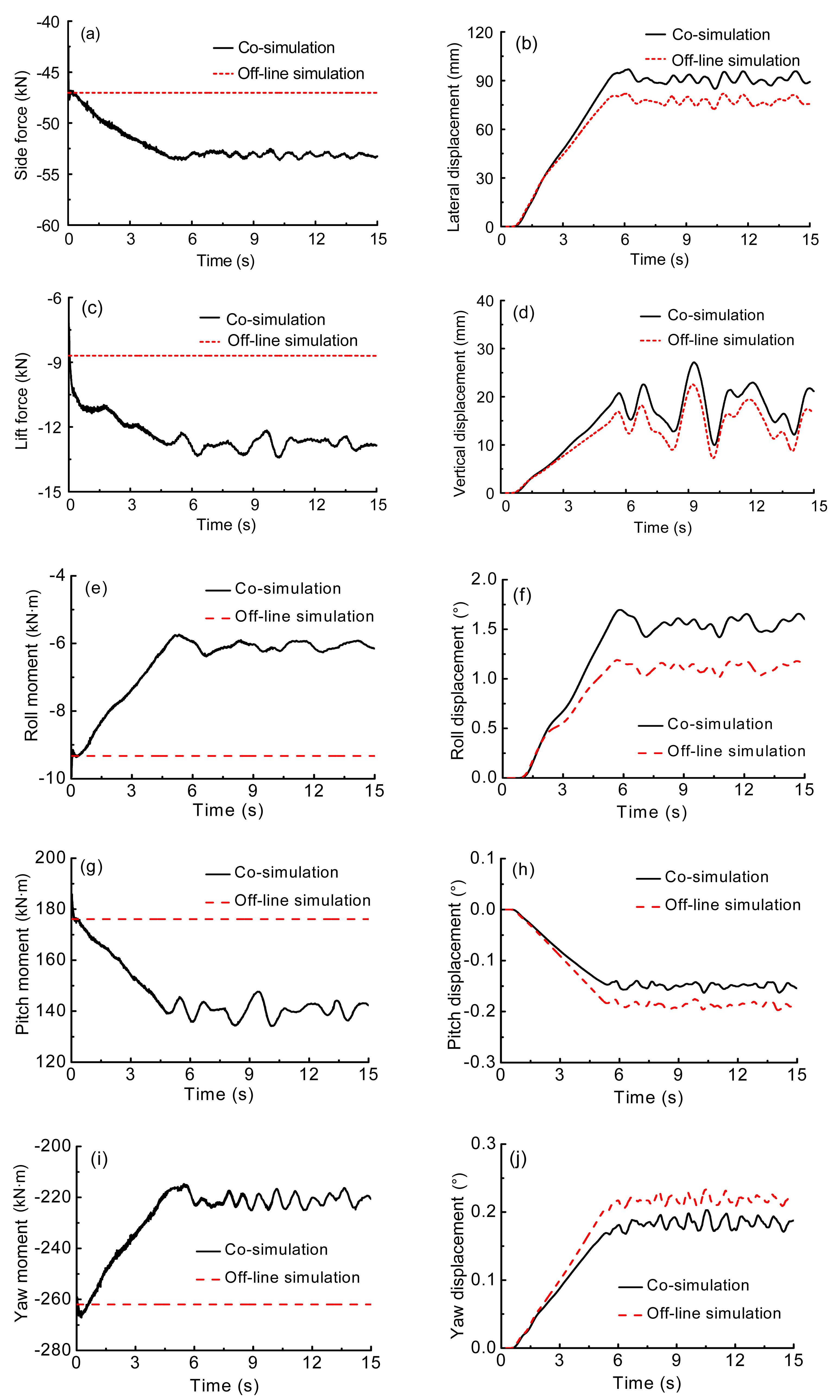
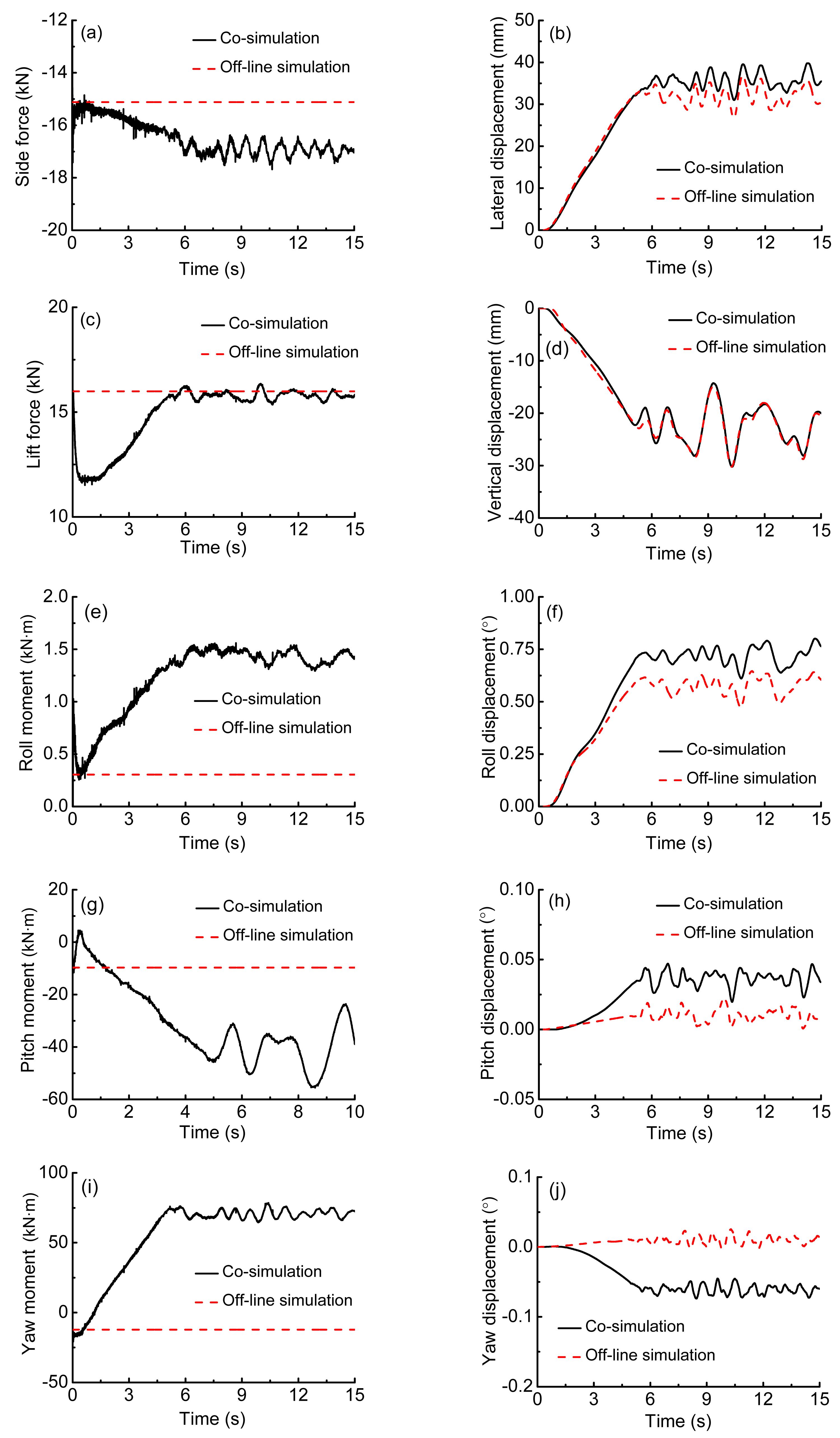
Figs. 6a–6j show a comparison of the responses of the head coach calculated by off-line simulation and co-simulation methods. When the interaction between airflow and a high-speed train is considered, the changes are as follows:
Fig.6 Responses of the head coach calculated by off-line simulation and co-simulation methods (a) Side force; (b) Lateral displacement; (c) Lift force; (d) Vertical displacement; (e) Roll moment; (f) Roll displacement; (g) Pitch moment; (h) Pitch displacement; (i) Yaw moment; (j) Yaw displacement
Baker et al. (2004) conducted that the magnitude of side and lift forces would increase with the consideration of the rolling motion of the carbody. The trends in the numerical results in this study are consistent with those of Baker et al. (2004)’s experiments.
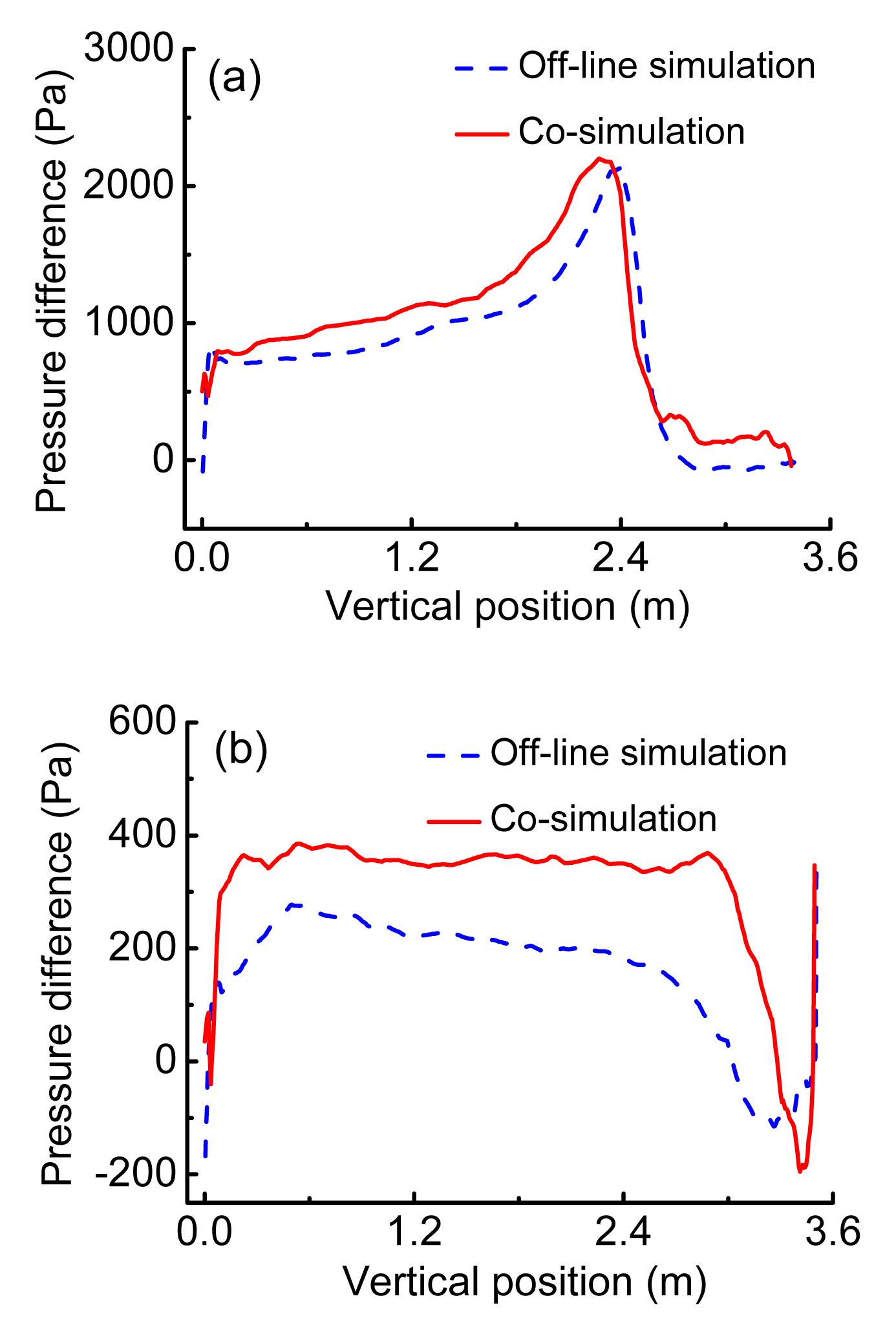
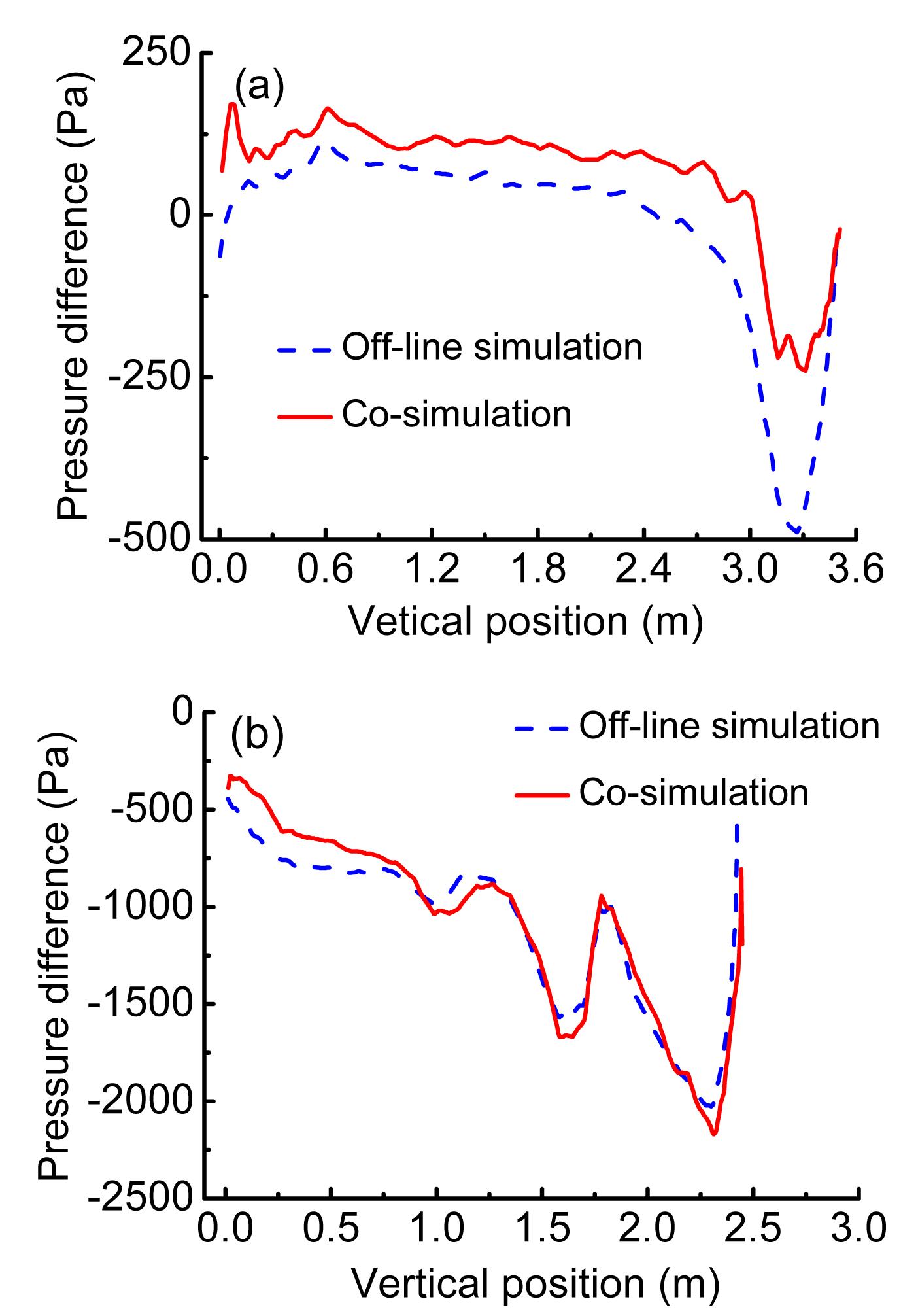
The magnitude of the side force and the roll moment is closely related to pressure differences between windward and leeward sides of the train. Figs. 7a and 7b show the pressure differences along the vertical dimension of the head coach, where d indicates the longitudinal distance between the cross-section and nose. There are two cross-sections: one at d=5 m located in the streamlined nose and the other one at d=18 m located in the non-streamlined region. Pressure differences at almost all vertical positions are higher in the co-simulation as the pressure on the windward side of the head coach increases. Therefore, the magnitude of the side force of the head coach increases by 10%. Consequently, the magnitude of the roll moment of the head coach increases.
Fig.7 Pressure differences along the vertical dimension of the head coach: d=5 m (a) and d=18 m (b)
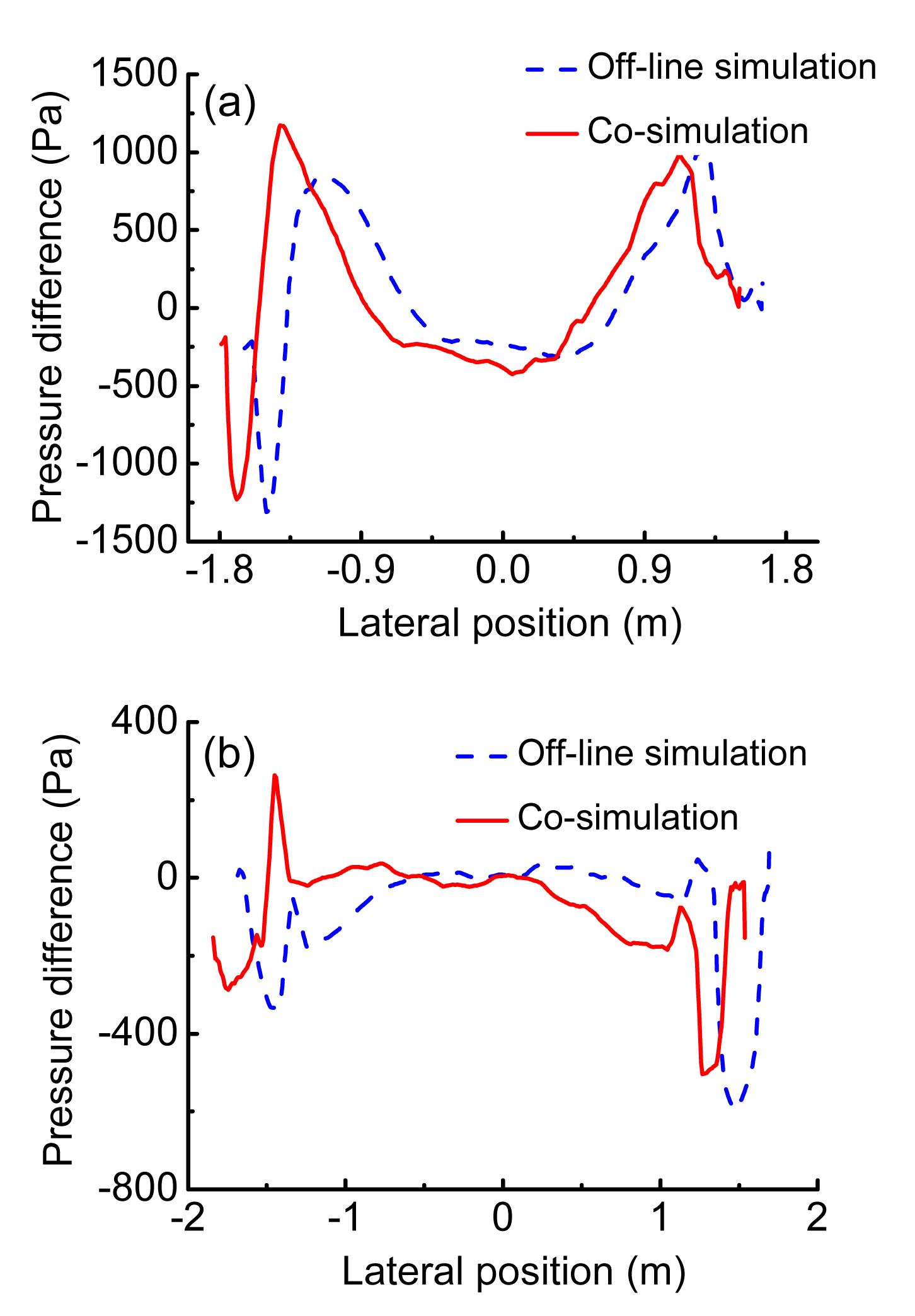
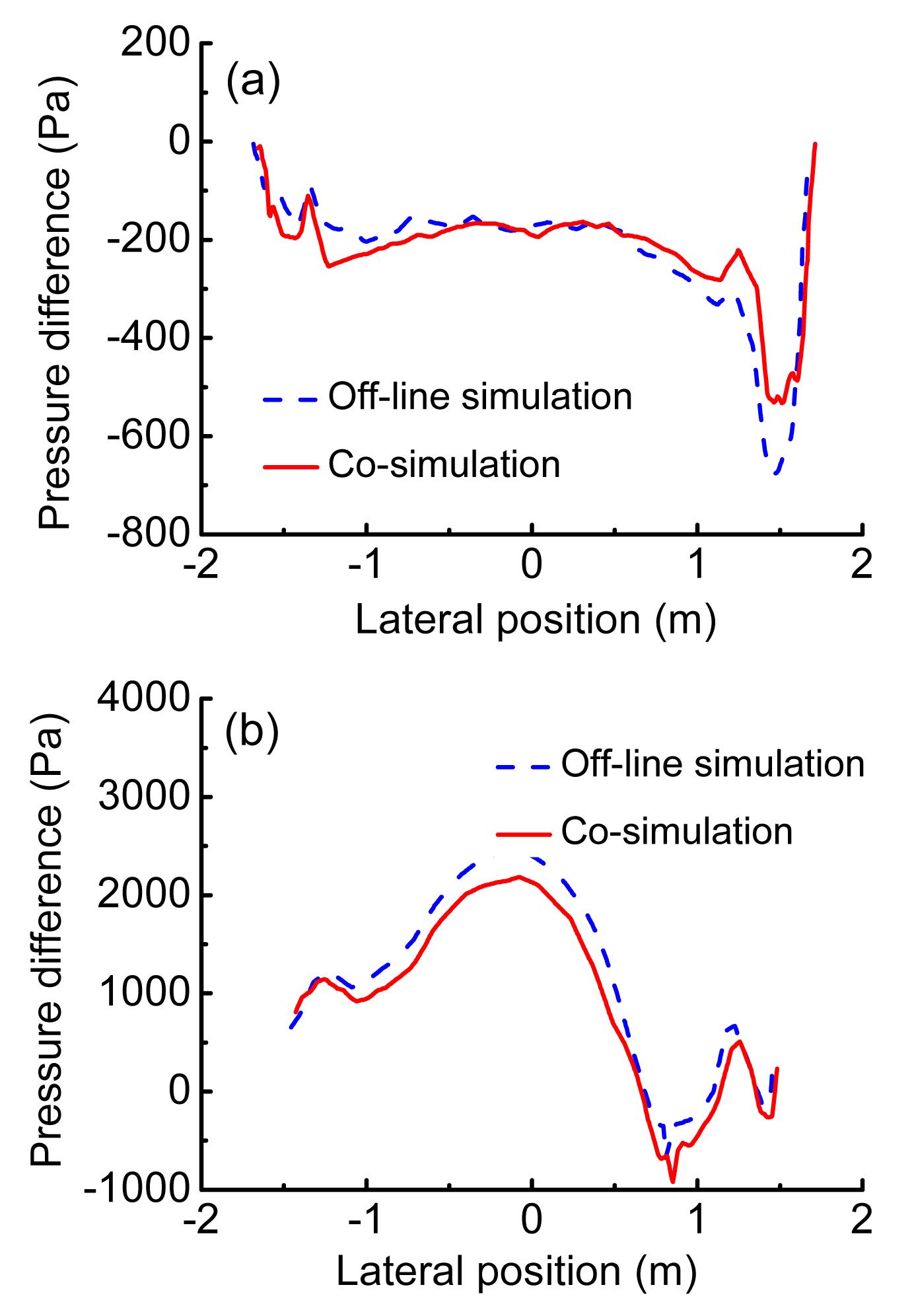
The magnitude of the lift force is closely related to pressure differences between the top and bottom of the train. Figs. 8a and 8b show pressure differences along the lateral dimension of the head coach. The pressure on the bottom of the head coach increases because of the rolling motion of the train body. The integral of pressure differences is greater in the co-simulation. As a result, the magnitude of the lift force increases.
Fig.8 Pressure differences along the lateral dimension of the head coach: d=5 m (a) and d=18 m (b)
5.1.2. Middle coach
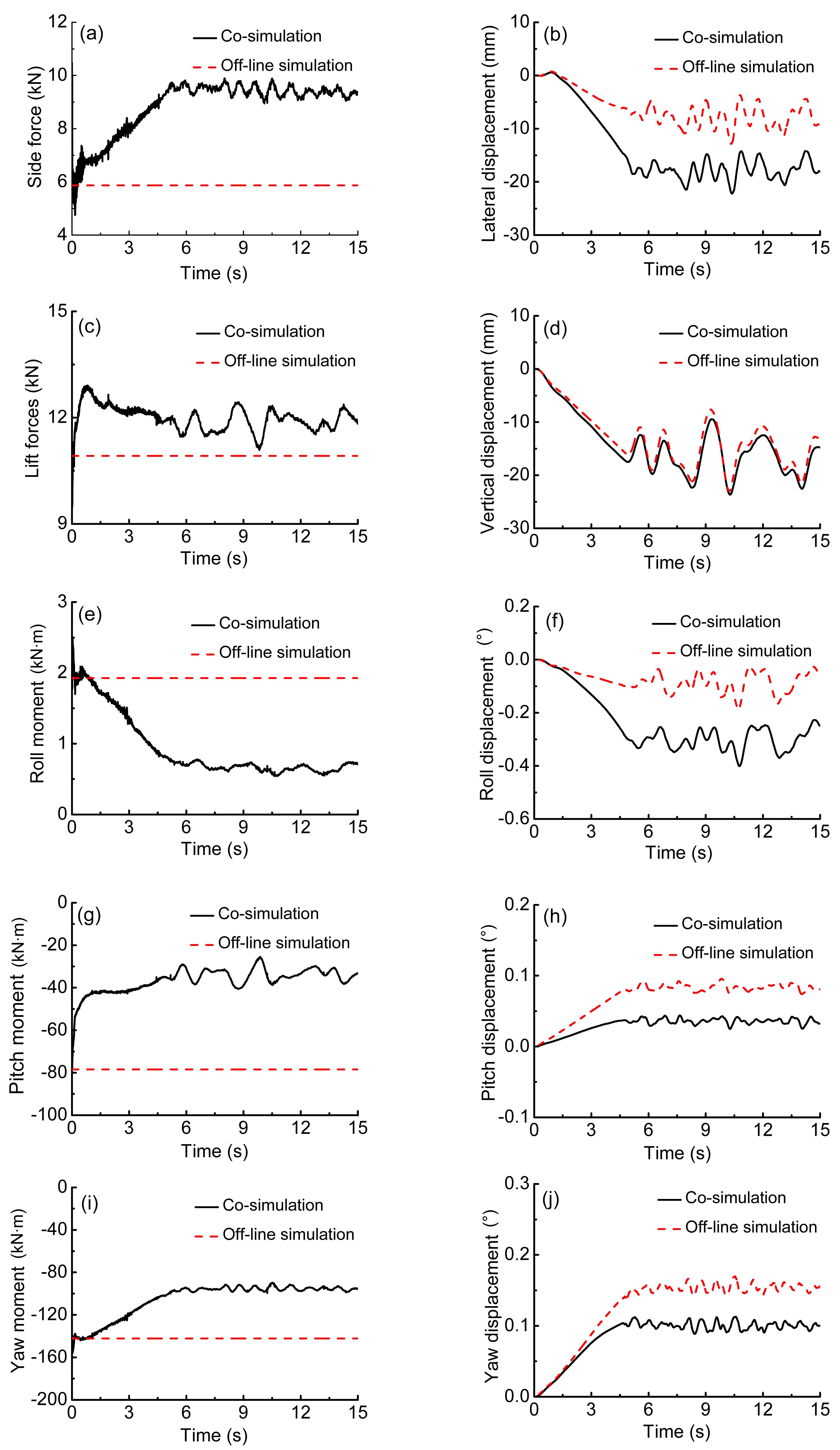
Figs. 9a–9j show a comparison of the responses of the middle coach calculated by off-line simulation and co-simulation methods. When the interaction between airflow and a high-speed train is considered, the changes are as follows:
Fig.9 Responses of the middle coach calculated by off-line simulation and co-simulation methods (a) Side force; (b) Lateral displacement; (c) Lift force; (d) Vertical displacement; (e) Roll moment; (f) Roll displacement; (g) Pitch moment; (h) Pitch displacement; (i) Yaw moment; (j) Yaw displacement
The pressure on two different cross-sections of the middle coach is in agreement because of the steady flow field around the middle coach. The pressure on the windward side of the middle coach almost increases and the pressure on the leeward side almost decreases. It is seen that the magnitude of the side force on the middle coach increases. According to Figs. 10a and 10b, pressure differences along the lateral dimension increase and the magnitude of the lift force on the middle coach decreases to some extent.
Fig.10 Pressure differences along vertical and lateral dimensions of the middle coach: vertical (a); lateral (b)
5.1.3. Tail coach
Figs. 11a–11j show a comparison of the responses of the tail coach calculated by off-line simulation and co-simulation methods. When the interaction between airflow and a high-speed train is considered, the changes are as follows:
Fig.11 Responses of the tail coach calculated by off-line simulation and co-simulation methods (a) Side force; (b) Lateral displacement; (c) Lift force; (d) Vertical displacement; (e) Roll moment; (f) Roll displacement; (g) Pitch moment; (h) Pitch displacement; (i) Yaw moment; (j) Yaw displacement
In the streamlined region, pressure differences between windward and leeward sides are much less than zero. Therefore, the direction of the side force on the tail coach is windward. Moreover, the pressure on the windward side of the tail coach increases. Figs. 12a and 12b show pressure differences along the vertical dimension of the tail coach. There are two cross-sections: one at d=65 m located in the non-streamlined region and the other at d=72.5 m located in the streamlined nose. In the non-streamlined region, pressure differences at almost all vertical positions are greater in the co-simulation. Figs. 13a and 13b show pressure differences along the lateral dimension of the tail coach at different cross-sections. In the streamlined region, the pressure differences are smaller in the co-simulation. As a result, the magnitude of the lift force increases.
Fig.12 Pressure differences along the vertical dimension of the tail coach: d=65 m (a) and d=72.5 m (b)
Fig.13 Pressure differences along the lateral dimension of the tail coach: d=65 m (a) and d=72.5 m (b)
5.2. Dynamic performances of vehicle-track
In this section, we describe the running safety of the train subjected to crosswind. Table 4 shows comparisons of the displacement calculated by different simulation methods. Displacements of the train include the lateral displacement y, the vertical displacement z, the roll displacement θ, the yaw displacement ψ, and the pitch displacement β. The values given in the table are the maximum or minimum values of the indexes. The lateral displacements of the head and middle coaches are toward the leeward side, which are opposite to that of the tail coach. Each component of the performance indexes of the head coach is the largest among the three coaches. Besides, the magnitude of displacements increases when the interaction is considered.
Table 4
Comparisons of displacements calculated by different simulation methods
Train type
Method
y (mm)
z (mm)
θ (°)
β (°)
ψ (°)
Head
Off-line simulation
82.03
22.52
1.17
−0.16
0.23
Co-simulation
95.33
27.14
1.65
−0.19
0.20
Middle
Off-line simulation
36.87
−30.17
0.65
0.04
0.02
Co-simulation
39.53
−30.27
0.79
0.02
−0.07
Tail
Off-line simulation
−12.88
−7.55
−0.19
0.09
0.17
Co-simulation
−22.18
−9.48
−0.40
0.04
0.11
The most important indexes of vehicle-track dynamics are safety indexes, including the wheel/rail vertical force, the lateral wheelset force, the derailment coefficient, and the wheel unloading rate. Table 5 shows comparisons of safety indexes calculated by different simulation methods. Among the three coaches, the head coach shows the largest increments in the safety indexes. The magnitude of the wheel unloading rate increases. The running safety of the train becomes worse with the consideration of the rolling motion of the carbody. Besides, the magnitude of the wheel set unloading rate and the derailment coefficient of the head coach increase by approximately 0.14 and 0.02, respectively.
Table 5
Comparisons of safety indexes calculated by different simulation methods
Train type
Method
Wheel/Rail vertical force (kN)
Lateral wheelset force (kN)
Derailment
Wheel unloading
Head
Off-line simulation
92.80
28.69
0.32
0.65
Co-simulation
96.40
32.84
0.34
0.79
Middle
Off-line simulation
77.51
13.32
0.19
0.44
Co-simulation
85.32
15.20
0.20
0.45
Tail
Off-line simulation
73.95
12.30
0.17
0.39
Co-simulation
81.92
13.89
0.19
0.40
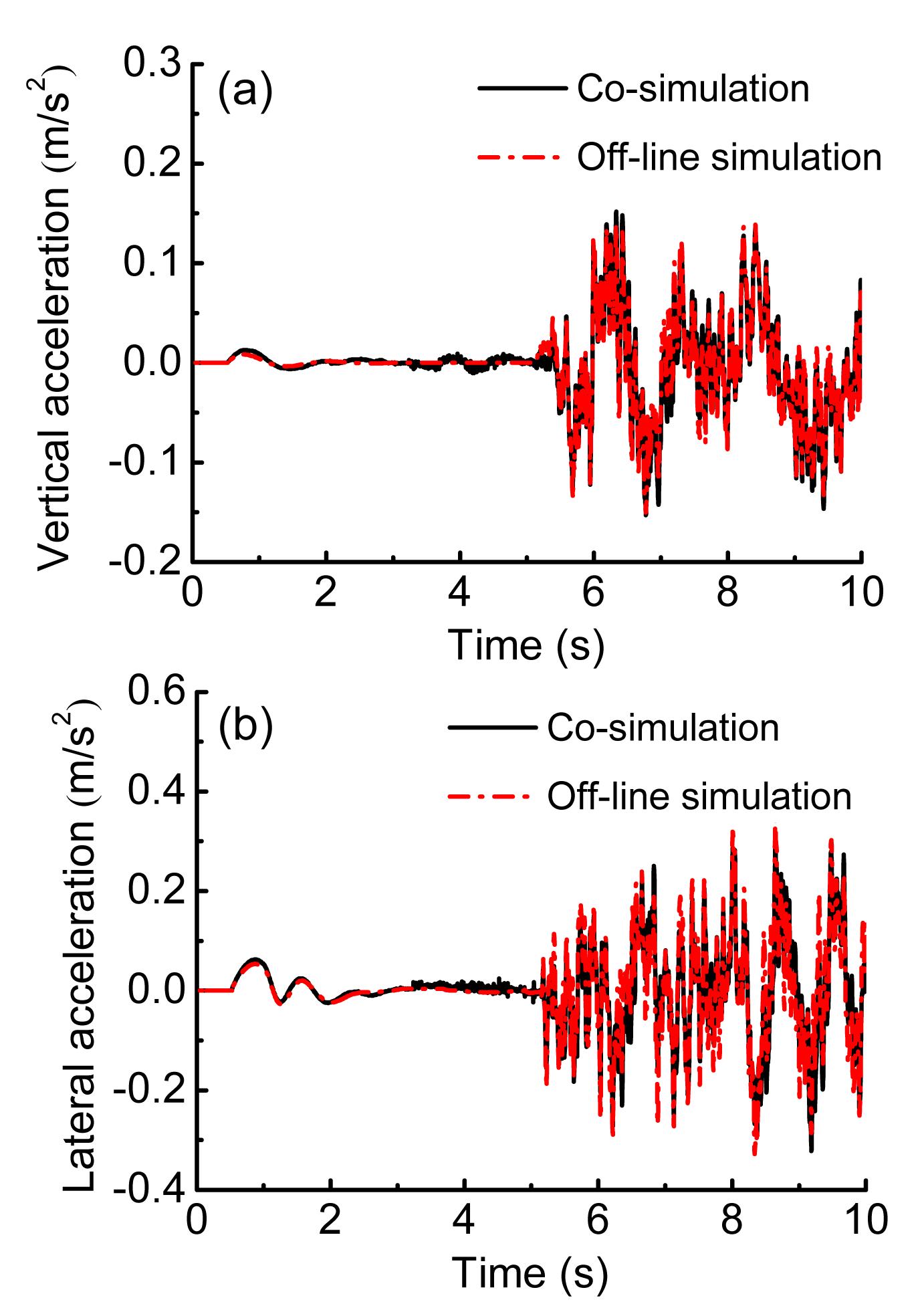
Figs. 14a and 14b show a comparison of the accelerations of the head coach calculated by different simulation methods. There is a slight difference in accelerations of the head coach.
Fig.14 Vertical (a) and lateral (b) accelerations of the head coach
6. Conclusions
A numerical approach to the interaction between airflow and a high-speed train is presented in this paper.
The interaction between airflow and a high-speed train significantly affects displacements and aerodynamic forces of the train subjected to crosswind.
The running safety of the train subjected to crosswind deteriorates when the interaction between airflow and a high-speed train is considered; however, there is a slight difference in accelerations of the head coach.
Among the three coaches, each component of the dynamic performance indexes of the head coach is the largest, and the head coach shows the largest increments in the safety indexes.
It is necessary to consider the interaction between airflow and a high-speed train subjected to crosswind.
[1] Baker, C.J., 1991. Ground vehicles in high cross winds part III: The interaction of aerodynamic forces and the vehicle system. Journal of Fluids and Structures, 5(2):221-241.
[2] Baker, C.J., 2010. The simulation of unsteady aerodynamic crosswind forces on trains. Journal of Wind Engineering and Industrial Aerodynamics, 98(2):88-99.
[3] Baker, C.J., Jones, J., Lopez-Calleja, F., Munday, J., 2004. Measurements of the cross wind forces on trains. Journal of Wind Engineering and Industrial Aerodynamics, 92(7-8):547-563.
[4] Baker, C.J., Hemida, H., Iwnicki, S., Xie, G., Ongaro, D., 2011. Integration of crosswind forces into train dynamic modelling. Proceedings of the Institution of Mechanical Engineers, Part F: Journal of Rail and Rapid Transit, 225(2):154-164.
[5] Bocciolone, M., Cheli, F., Corradi, R., Muggiasca, S., Tomasini, G., 2008. Crosswind action on rail vehicles: Wind tunnel experimental analyses. Journal of Wind Engineering and Industrial Aerodynamics, 96(5):584-610.
[6] Cheli, F., Ripamonti, F., Rocchi, D., Tomasini, G., 2010. Aerodynamic behaviour investigation of the new EMUV250 train to cross wind. Journal of Wind Engineering and Industrial Aerodynamics, 98(4-5):189-201.
[7] Chiu, T.W., 1995. Prediction of the aerodynamic loads on a railway train in a cross-wind at large yaw angles using an integrated two- and three-dimensional source/vortex panel method. Journal of Wind Engineering and Industrial Aerodynamics, 57(1):19-39.
[8] Diedrichs, B., 2003. On computational fluid dynamics modeling of crosswind effects for high-speed rolling stock. Proceedings of the Institution of Mechanical Engineers, Part F: Journal of Rail and Rapid Transit, 217(3):203-226.
[9] Diedrichs, B., Sima, M., Orellano, A., Tengstrand, H., 2007. Crosswind stability of a high-speed train on a high embankment. Proceedings of the Institution of Mechanical Engineers, Part F: Journal of Rail and Rapid Transit, 221(2):205-225.
[10] Ding, Y., Sterling, M., Baker, C.J., 2008. An alternative approach to modeling train stability in high cross winds. Proceedings of the Institution of Mechanical Engineers, Part F: Journal of Rail and Rapid Transit, 222(1):85-97.
[11] Khier, W., Breuer, M., Durst, F., 2000. Flow structure around trains under side wind conditions: a numerical study. Computers & Fluids, 29(2):179-195.
[12] Li, T., Zhang, J.Y., Zhang, W.H., 2011. Performance of vehicle-track coupling dynamics under crosswinds. Journal of Traffic and Transportation Engineering, (in Chinese),9:55-60.
[13] Li, T., Zhang, J.Y., Zhang, W.H., 2011. Nonlinear characteristics of vortex-induced vibration at low Reynolds number. Communications in Nonlinear Science and Numerical Simulation, 16(7):2753-2771.
[14] Orellano, A., Schober, M., 2006. Aerodynamic Performance of a Typical High-speed Train. , Proceedings of the 4th WSEAS International Conference on Fluid Mechanics and Aerodynamics, Elounda, Greece, 18-25. :18-25.
[15] Shao, X.M., Wan, J., Chen, D.W., Xiong, H.B., 2011. Aerodynamic modeling and stability analysis of a high-speed train under strong rain and crosswind conditions. Journal of Zhejiang University-SCIENCE A (Applied Physics & Engineering), 12(12):964-970.
[16] Suzuki, M., Tanemoto, K., Maeda, T., 2003. Aerodynamic characteristics of train/vehicles under cross winds. Journal of Wind Engineering and Industrial Aerodynamics, 91(1-2):209-218.
[17] Thomas, D., Diedrichs, B., Berg, M., Stichel, S., 2010. Dynamics of a high-speed rail vehicle negotiating curves at unsteady crosswind. Proceedings of the Institution of Mechanical Engineers, Part F: Journal of Rail and Rapid Transit, 224(6):567-579.
[18] Xu, Y.L., Ding, Q.S., 2006. Interaction of railway vehicles with track in cross-winds. Journal of Fluids and Structures, 22(3):295-314.
[19] Zhai, W.M., Cai, C.B., Guo, S.Z., 1996. Coupling model of vertical and lateral vehicle/track interactions. Vehicle System Dynamics, 26(1):61-79.
Open peer comments: Debate/Discuss/Question/Opinion


Open peer comments: Debate/Discuss/Question/Opinion
<1>