Affiliation(s):
1.
State Key Laboratory of Fluid Power Transmission and Control, Zhejiang University, Hangzhou 310027, China; moreAffiliation(s): 1.
State Key Laboratory of Fluid Power Transmission and Control, Zhejiang University, Hangzhou 310027, China; 2.
Department of Ocean Science and Engineering, Zhejiang University, Hangzhou 310027, China; less
Shi-jun Wu, Can-jun Yang, Hao-cai Huang, Ying Chen. Development of an electric control gas-tight sampler for seafloor hydrothermal fluids[J]. Journal of Zhejiang University Science A, 2014, 15(2): 120-129.
@article{title="Development of an electric control gas-tight sampler for seafloor hydrothermal fluids", author="Shi-jun Wu, Can-jun Yang, Hao-cai Huang, Ying Chen", journal="Journal of Zhejiang University Science A", volume="15", number="2", pages="120-129", year="2014", publisher="Zhejiang University Press & Springer", doi="10.1631/jzus.A1300233" }
%0 Journal Article %T Development of an electric control gas-tight sampler for seafloor hydrothermal fluids %A Shi-jun Wu %A Can-jun Yang %A Hao-cai Huang %A Ying Chen %J Journal of Zhejiang University SCIENCE A %V 15 %N 2 %P 120-129 %@ 1673-565X %D 2014 %I Zhejiang University Press & Springer %DOI 10.1631/jzus.A1300233
TY - JOUR T1 - Development of an electric control gas-tight sampler for seafloor hydrothermal fluids A1 - Shi-jun Wu A1 - Can-jun Yang A1 - Hao-cai Huang A1 - Ying Chen J0 - Journal of Zhejiang University Science A VL - 15 IS - 2 SP - 120 EP - 129 %@ 1673-565X Y1 - 2014 PB - Zhejiang University Press & Springer ER - DOI - 10.1631/jzus.A1300233
Abstract: Submarine hydrothermal vents occur over a wide depth range from a few meters to several thousands of meters. Most existing hydrothermal fluidsamplers are focused on deep-sea environments and are not suited for collecting shallow-water fluids. In this study, a new gas-tightsampler which can be easily deployed by both submersibles and scuba divers to collect fluid samples from both deep-sea and shallow-water hydrothermal vents is presented. The proposed sampler uses an electric control sampling valve for fluid collection and a system to measure and display the temperature of the hydrothermal fluid while sampling. It is capable of working in manual mode to be controlled via external signals, or in automatic mode to collect a fluid sample according to the temperature. The master-slave architecture of the electronic system makes the sampler flexible in meeting many different deployment requirements. The performance of the sampler has been demonstrated by preliminary field tests at a shallow-water hydrothermal vent site.
Darkslateblue:Affiliate; Royal Blue:Author; Turquoise:Article
Article Content
1. Introduction
It is well known that seafloor hydrothermal activity plays an important role in regulating the exchange of heat and mass between seawater and the oceanic crust. Deep-sea hydrothermal vents and exotic organisms were first discovered in 1977 at Galapagos Rift, a spur of the East Pacific Rise (Corliss et al., 1979). Since then, many more deep-sea hydrothermal sites have been found along the mid-ocean ridges and in back-arc basin settings (Bowers et al., 1988; Campbell et al., 1988; Fouquet et al., 1991; Gamo et al., 2001). These sites are typically located at water depths of over 2000 m and are spectacularly featured with so-called “black smokers”, which emit high-temperature hydrothermal fluids with black clouds of metal sulphide particles. Most studies of seafloor hydrothermal activity have focused on these hydrothermal sites. However, submarine hydrothermal activity is not confined to deep-water environments. Recently, a number of shallow-water hydrothermal vents have been found and studied at the flanks of volcanic islands and on the tops of seamounts (Pichler et al., 1999; Cardigos et al., 2005; Chen et al., 2005a; 2005b). Shallow-water hydrothermal vent fluids generally present transitional chemical characteristics between deep-sea and sub-aerial vents. They provide an exceptional opportunity to study the differences and similarities between submarine and sub-aerial venting, and provide a more comprehensive understanding of the heat and mass exchange between seawater and the oceanic crust (Pichler et al., 1999).
Hydrothermal fluid samplers are one of the most important engineering tools for the study of hydrothermal activity. To meet the requirements of scientific research, a variety of samplers have been developed to collect fluids from seafloor hydrothermal vents. These devices include the often mentioned “major” sampler (Von Damm et al., 1985), the so-called “Lupton” gas-tight sampler (Edmond et al., 1992), and the isobaric gas-tight sampler (Seewald et al., 2002), etc. They are primarily dedicated to deep-sea environments and rely on the operation of manipulators installed on submersibles. Thus, they are not suitable for collecting hydrothermal fluids in shallow water where the deployment of a submersible is neither practical nor economical. Currently, the collection of fluid samples at these shallow sites is usually fulfilled by plastic bottles or medical syringes operated by scuba divers (Pichler et al., 1999; Chen et al., 2005a; Valsami-Jones et al., 2005). Although these methods are quite simple, however, due to the lack of temperature measuring while sampling, it is often difficult to collect high-purity fluid samples as the hydrothermal fluids usually have steep temperature gradient when they erupt out of the vent and mix with seawater (Fornari et al., 1997). Besides, the gas-tight performance of these devices is often not satisfactory for the analysis of gas components in hydrothermal fluids.
The purpose of this study is to present an electric control gas-tight sampler that is convenient for deployment by both submersibles and scuba divers. Thus, it can be easily used to collect hydrothermal fluids from both deep-sea and shallow-water hydrothermal vents. Due to the employment of an electric control sampling valve, the new sampler simplifies underwater operation and can work in either manual or automatic mode. Moreover, the integrated temperature measurement system allows the sampler to monitor the fluid temperature while sampling at the same point and display the temperature value underwater in real time. It also eliminates the wire connection with a submersible which may cause problems from time to time.
2. Structural design of the sampler
2.1. Instrument description
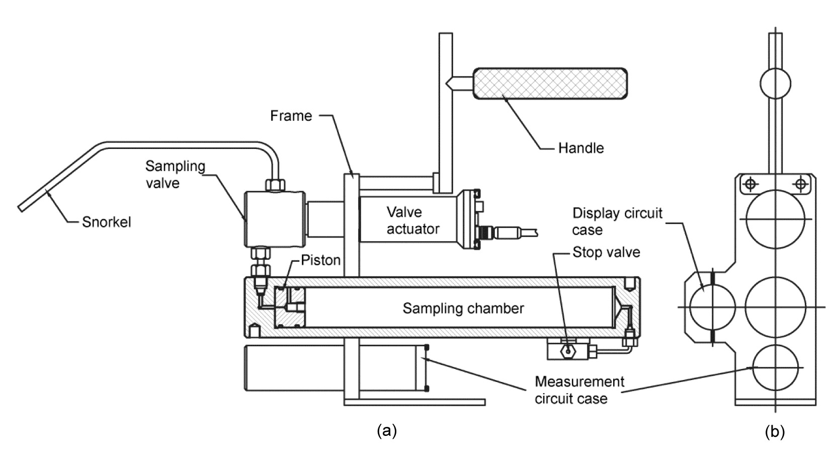
As shown in Fig. 1, the new electric control sampler consists of four major components: (1) a sampling valve with good sealing capability under high pressure, and a valve actuator which is used to open and close the sampling valve; (2) a sampling cylinder which includes a sampling chamber, a piston, and a stop valve. The sampling chamber is connected to the sampling valve; (3) a measurement circuit case inside which a printed circuit board (PCB) is running to measure the temperature of fluid and control the valve actuator (the cable connection is not shown); (4) a display circuit case which is used to display the temperature and provide the sampling trigger signal. All of the major components are fixed in a frame. Without the snorkel and handle, the sampler is 39 cm long, 13 cm wide, and 23 cm high; it weighs approximately 9 kg in air and 7 kg in seawater. The current configuration shown in Fig. 1 is suitable for operation by scuba divers in shallow water. In addition, the sampler is also suitable for deployment by underwater vehicles, such as human occupied vehicles (HOVs) and remotely operated vehicles (ROVs), just by replacing the handle and the display circuit case. For deep-sea deployment, the sampler will have two chambers and two pistons between which an orifice is used to regulate the flow rate during sampling (Seewald et al., 2002).
Fig.1 Schematic illustration of the electric control gas-tight sampler configurated for shallow water (a) Front view of the sampler; (b) Right view of the sampler
The basic working principle of the electric control sampler is similar to the previous isobaric gas-tight sampler (Seewald et al., 2002). Before deployment, the piston inside the sampling chamber is positioned against the sampling valve (Fig. 1). The snorkel and the dead volume between the sampling valve and piston are filled with local bottom seawater. The chamber at the rear of the piston is filled with pure nitrogen gas whose pressure is adjusted to an appropriate value for the deployment depth. The pre-filled nitrogen gas is used to maintain the fluid sample at in situ seafloor pressure during recovery. For sample collection, the sampler is held by a scuba diver or the manipulator of a submersible, and the snorkel is inserted into the hydrothermal vent. The fluid temperature is measured by a thermocouple bound together with the snorkel and displayed by the display chamber in real time. Once the temperature is stabilized, a trigger signal is produced automatically or manually (depending on the working mode of the sampler, see Section 2.3 for a detailed description) and then the sampling valve is opened by the actuator. Hydrothermal fluid fills the sampling chamber, forcing the piston to move towards the other side. After a preset filling time, the sampling valve is closed. When the sampler is retrieved, extraction of the fluid sample is achieved by replacing the snorkel with a micrometering valve and attaching a water pump to the stop valve of the sampling chamber. Then distilled water is pumped into the sampling chamber at the rear of the piston as fluid is removed through the micrometering valve. Depending on the desired analytical method, the fluid sample may be completely extracted at one time or sub-sampled a number of times without degassing the remaining fluid. After completing the extraction of the fluid sample, the sampling valve and chamber are cleaned and prepared for the next deployment.
2.2. Sampling valve and actuator
As mentioned above, the sampling valve is one of most important parts of the sampler for ensuring the success of sampling. To obtain a high quality fluid sample, the seawater cannot be allowed to seep into the sampler before sampling. Similarly, the fluid sample once obtained must not be allowed to leak out during the recovery of sampler from the seafloor. Thus, the sampling valve must have bidirectional sealing capability under high pressure. Moreover, the sampling valve should also have a good thermal tolerance and corrosion resistance since most hydrothermal fluids are quite hot and highly corrosive. To address these issues, a custom-made sampling valve is applied. As shown in Fig. 2, the sampling valve employs two sliding O-ring seals and a cone seal comprising a valve poppet and seat. Cone seals are widely used in fluid and air control valves because of their good sealing capability and ease of machining (Bergada and Watton, 2004; Dou et al., 2005). A spring is employed to produce an initial sealing force between the valve poppet and the seat. A special feature of the sampling valve is the pressure-balanced valve poppet (Chen et al., 2007). Because the two sliding O-ring seals and the valve seat have the same diameter, the pressure forces on the valve poppet are always equal and opposite no matter which port is subjected to high pressure, that is, the valve poppet is always pressure-balanced. One benefit of using a pressure-balanced valve poppet is that the sealing force does not vary with the pressure of the operation fluid. Therefore, the valve actuator only needs to overcome the spring force and a little friction force to move the poppet and open the valve. Once the external actuating force is released, the valve closes again automatically (Wu et al., 2012). To achieve good repeatability of the contact seal, an alignment pin is used to prevent rotation of the valve poppet, thus ensuring the same contact surface with the valve seat each time.
Fig.2 Structure of the sampling valve (modified from Wu et al. (2012))
Since the hydrothermal fluid is highly corrosive, the parts of the sampling valve that can come into contact with a fluid sample, including the valve body, valve poppet, and pocket are constructed of titanium alloy (Ti-6Al-4V) because of its high strength and excellent resistances to corrosion and heat. The valve seat is made of polyetheretherketone (PEEK) as it is much softer than titanium alloy, so a non-leakage contact seal between the valve poppet and the seat can be easily achieved. Besides, PEEK also has a good thermal tolerance (260 °C for long-term use) and corrosion resistance which can reasonably meet the requirements of hydrothermal fluid collecting (Taylor et al., 2006; Victrex Inc., 2009). All the O-rings of the sampling valve are made of perfluoroelastomer. It should be pointed out that when the sampling valve with a PEEK seat is used to collect deep-sea high-temperature (approaching 400 °C) hydrothermal fluids, the sampler snorkel (Fig. 1) and filling rate will be properly designed and regulated so that the temperature of incoming sample fluids can be lowered from 400 °C to below 260 °C (Taylor et al., 2006). Otherwise, the PEEK valve seat may be damaged or degraded.
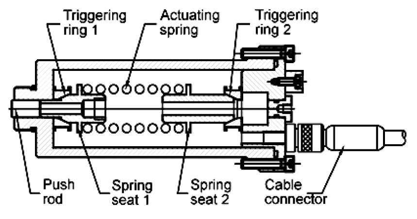
According to the characteristics and working principle of the sampling valve, a single-shot linear actuator is designed (Wu et al., 2009). As shown in Fig. 3, the actuator consists of a pressure case inside which a preloaded actuating spring is used to produce an output force and linear movement. When not actuated, the spring is compressed and constrained by two triggering rings and spring seats. Each triggering ring consists of four individual quarter rings, which are assembled together and held tightly by a wire loop (Figs. 4a and 4b). The wire loop includes a steel wire tied with a piece of fiber which is encircled around a metal film resistor (Fig. 4c). When energizing the actuator, current is passed through the resistor of triggering ring 1, which then heats and melts the fiber. As soon as the wire loop is broken, the quarter rings fan out, allowing the actuating spring to move forward to produce an output force and displacement. When it is time to release the actuating force, the triggering ring 2 is then triggered in the same way and the spring comes back to its free state. Once the actuator has been fired, the actuating spring needs to be loaded again for the next deployment. The maximal output force of the actuator is dependent on the load capacity of the triggering ring, which can constrain the preloaded actuating spring before breaking. More specifically, it is limited by the strength of the wire loop. The fiber used here is a high performance polyethylene fiber, which is usually called Dyneema fiber, which has very high strength and elastic modulus (van Dingenen, 1989; Hoppe, 1997). Consequently, the load capacity of the triggering ring is dramatically improved. For more information about this actuator, please refer to Wu et al. (2009).
Fig.3 Schematic illustration of the sampling valve actuator (modified from Wu et al. (2009))
Fig.4 Schematic illustration of the triggering ring (Wu et al., (2009)) (a) Front view; (b) Top view; (c) Illustration of the wire loop
2.3. Display chamber
Hydrothermal fluids usually have a steep temperature gradient as they mix with seawater. During the collection of hydrothermal fluids, temperature is used as the guide for the snorkel placement, as the highest temperature indicates where the vent fluid is undergoing the smallest amount of mixing with the surrounding seawater. Existing samplers mostly have hardwired connections or non-contact communication with underwater vehicles so it is convenient for the operators to use a computer to read the temperature data and control the samplers. However, this method is not practicable for the samplers operated by scuba divers when they are used to collect fluid samples from shallow-water hydrothermal vents. Besides, sometimes connecting a hardwire from the sampler to an underwater vehicle may be not suitable for safety reasons. Therefore, a shallow-water display chamber and a deep-sea display chamber are designed for the new sampler to facilitate the deployment by scuba divers and underwater vehicles, respectively.
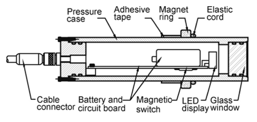
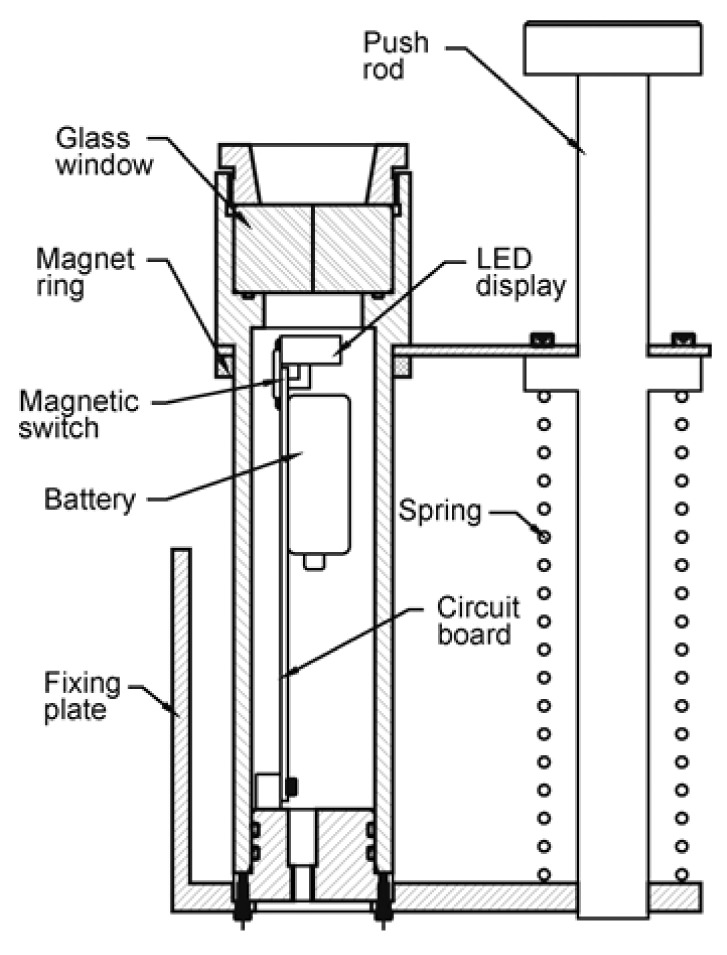
As shown in Figs. 5 and 6, all the electronic parts are encapsulated in a pressure case. A circuit board is running to communicate with the measurement board (inside the measurement chamber) and to convert the original data to the temperature value, which is then displayed by light-emitting diodes (LEDs). In addition, a magnetic reed switch is connected to the circuit to produce a manual trigger signal when ready to take a sample. The switch is placed as close to the chamber’s center line as possible since the magnetic field intensity there is the strongest. A magnet ring is installed outside the chamber, the initial position of which is adjusted to keep the magnetic reed switch in the “ON” position. Once the magnet ring is removed, the switch turns from “ON” to “OFF”, and then a voltage jump is produced and detected by the circuit. For deployment by scuba divers, the shallow-water display chamber is fixed on the frame of the sampler and has a hardwire connection with the measurement chamber via an underwater cable. An adhesive tape and elastic cord are used to facilitate the fixing and removal of the magnet ring (Fig. 5). For deployment by underwater vehicles in the deep sea, the display chamber is redesigned to withstand high pressure and to facilitate operation by a manipulator. As shown in Fig. 6, the display chamber is installed on a fixing plate which is then placed in the basket of an underwater vehicle, where it is easy to observe the temperature by a camera. The magnetic reed switch can be conveniently triggered using the manipulator to depress the push rod, which can come back to its original position with the help of a spring when the pushing force is released. Furthermore, the connection between the display chamber and the measurement chamber can be replaced by an inductively coupled link (ICL), which allows near-field wireless serial communication via a pair of simple coils (Fornari et al., 1997). As a result, the display chamber is separated from the sampler. This makes it feasible to use only one display chamber to communicate with several samplers just by switching the ICL coils during each dive.
Fig.5 Schematic illustration of the shallow-water display chamber
Fig.6 Schematic illustration of the deep-sea display chamber for underwater vehicles
The sampler is designed to work at the seafloor with a maximum depth of 4000 m. Wu et al. (2009) demonstrated that the sampling valve, actuator, and sampling chamber worked well at an ambient pressure of 40 MPa. Moreover, the deep-sea display chamber must withstand pressures up to 40 MPa. The strength of the glass window was calculated based on the equation for a flat circular plate.
,
where Pc is the collapse pressure, σ is the fracture strength of glass, t is the thickness, and d is the unsupported diameter. In our current design, a fused silica glass window is used, the fracture strength of which is 48.3 MPa. The calculated collapse pressure is 124 MPa according to Eq. (1). So the glass window has a safety factor of 3 when working at the maximum depth of 4000 m. The display chamber has also been tested in a high-pressure vessel at a pressure of 40 MPa for 8 h, and no leakage or failure is found.
3. Temperature measurement and sampling control system
3.1. Hardware architecture
The main functions of the sampler’s electronic system are to digitize the signals of the temperature sensors, display temperature values in real time, and control the valve actuator. To make the system flexible enough to meet different application requirements, we constructed a master-slave hardware architecture which is schematically illustrated in Fig. 7.
Fig.7 Functional block diagram of the hardware architecture
Power consumption and size are generally the main concerns for deep-sea electronic equipment design. The MSP430 micro controller unit (MCU) from Texas Instrument is one of the new generation of ultra-low power microcontrollers. It is widely used in battery-operated instruments like data loggers, hand-held meters, and medical equipments (Wang et al., 2009; Zhao et al., 2009; Tan et al., 2010). In addition to extremely low power consumption (ranging from several microwatts in active mode to less than 0.1 mW in sleep mode), MSP430 MCU has a series of models with abundant on-chip peripherals, such as analog-to-digital (AD) converters, digital inputs/outputs (I/Os), timers, and universal synchronous/asynchronous receive/transmit (USART) interfaces (Texas Instruments Corporation, 2003). So it can significantly simplify the circuit design as well as reduce the size.
In our application, two MSP430F149 MCUs are adopted in the master and slave circuits. As Fig. 7 shows, in the slave unit, signals from the thermocouple and thermistor are filtered and amplified by the signal conditioning module, and then digitized using the MSP430’s built-in 12-bit AD converter. Since the valve actuator employs heating the metal film resistor quickly to melt the fiber, a large driving current (generally hundreds of micro amperes) is required. A ULN2068 is one of the high-voltage and high-current Darlington arrays from Allegro MicroSystems, which is designed for interface between low-level logic and a variety of peripheral loads like relays, solenoids, and heaters. A ULN2068 has a high output current up to 1.5 A while requires a low input current less than 1 mA. Besides, it integrates four Darlington switches in a single chip with compact sizes as small as 13 mm×10 mm×2.5 mm (Allegro MicroSystems, Inc., 2002). Therefore, it is an ideal solution for the design of a driving circuit. The master unit consists of an MSP430F149 and an LED display. A trigger signal from the magnetic reed switch is detected using the MCU’s interrupt port. The master unit communicates with the slave unit via RS232 or ICL.
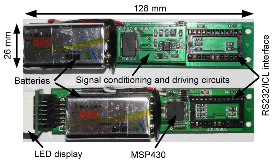
Prototype circuit boards of master and slave units are shown in Fig. 8. To minimize the dimensions of the slave unit, the signal conditioning and driving circuits are laid out on a small individual PCB board, which is then stacked on the main board. Even with the battery attached, the circuit board is as small as 128 mm×26 mm. Similarly, the RS232 and ICL communication modules are also designed on two small PCB boards, respectively (not shown in Fig. 8). They use the same interface connecting to the master and slave units, thus making it very convenient to change the communication modes.
Fig.8 Circuit boards of the slave (up) and master (down) units
3.2. Software architecture
Upon startup, the master unit sends out a temperature measurement command periodically at preset intervals. Once the command is received, the slave unit starts digitizing the signals. After finishing the AD conversion, the data is transmitted back to the master unit to be converted to a temperature value and displayed via LEDs. For the valve control, two working modes are considered in the software design. In the manual working mode, the master unit sends out a valve opening command according to the interrupt event caused by the magnetic reed switch. Consequently, the slave unit continuously outputs current for several seconds (depending upon the time needed to heat the resistor) to open the sampling valve. After a preset filling time counted using the MSP430’s built-in 16-bit timer, the master unit sends out a valve closing command, and then the slave unit responds in the same way to close the valve. In the automatic working mode, the master unit does not need an external trigger signal but sends out the valve opening command according to the temperature values. A reference temperature is set in the program prior to each deployment. When the measured temperature reaches the reference temperature and remains stable for a period of time, the master unit sends out the valve opening command automatically. Thus, this working mode simplifies the operation of the sampler during deployment. However, it requires the operator to predict the temperatures of hydrothermal fluids, which may be difficult at unfamiliar vents. According to actual deployment requirements, the working modes can be easily changed by downloading a new program, and all the parameters can be reset by commands from a computer.
4. Preliminary deployments and results
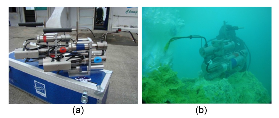
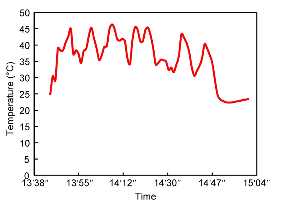
In May 2010, two sets of new electric control samplers were developed and went through the first sea trial at the hydrothermal vent site near off Kueishantao Islet (24°51′N, 121°55′E) located at a tectonic junction of the fault system extension of Taiwan and the southern rifting end of the Okinawa Trough (Chen et al., 2005a), to verify their mechanical and electronic capabilities. Since hydrothermal vents in this field are in shallow water with depths of about 10–30 m, the samplers were deployed by scuba divers (Fig. 9). Prior to deployment, each sampler was prepared as described in Section 2.1, and the pre-filled nitrogen gas was kept at one atmosphere pressure. During the first deployment, the samplers were used successfully to take fluid samples from a low-temperature vent characterized by discharging a whitish fluid at a depth of 18 m. The temperature of the hydrothermal vent was measured to be approximately between 35 °C and 46 °C (Fig. 10). In general, the mechanical parts of the sampler, including the sampling valve, valve actuator, sampling chamber, and electronic system were shown to work well. During the second deployment, the two samplers were tested at a shallower vent with a depth of 8 m. The fluid temperature was measured as high as 116 °C. The sampling valves and actuators worked properly according to the operation of scuba divers. Unfortunately, the hydrothermal vent is so shallow that the fluid pressure was not high enough to move the piston, hence no sample was collected.
Fig.9 Two sets of the new electric control samplers on the dock before sea trial (a) and deployment of the sampler by a scuba diver in a shallow-water hydrothermal vent off Kueishantao Islet (b)
Fig.10 Temperature of the white vent during the collection of a hydrothermal fluid sample
Laboratory tests were carried out after the sea trial to verify if the sampler has the ability to collect samples from very shallow sites with depths less than 10 m. It was found that when the two O-rings of the piston were lubricated by grease, the piston could be moved by a pressure less than 105 Pa. During another test, the chamber at the rear of the piston was evacuated after the sampling valve was closed. Then the sampler was successful in sucking water from a bucket when the sampling valve was opened. In this case, the sampler is able to collect samples from any shallow sites. Fluorolube grease is recommended for the O-rings during actual deployment of the sampler.
The fluid samples obtained were analyzed at an onshore laboratory (Table 1). It should be noted that the dissolved oxygen (DO) concentrations in the fluids collected by the new samplers were quite low compared to previous study (Kuo, 2001). Because oxygen is nearly absent in the endmember of hydrothermal fluids, the DO in the fluid samples is regarded as having been introduced by the pre-filled seawater in the sampler’s dead volume (as described in Section 2.1) and the entrainment of ambient seawater during sampling. The low DO concentrations in the samples indicate that the new sampler is capable of collecting high-purity hydrothermal fluid samples.
Table 1
Parts of the chemical analysis results of the fluid samples
Sample
DO (%)
pH
SiO2 (μmol/kg)
Salinity
No. 1
3.7
5.28
89.0
33.1
No. 2
4.5
5.99
55.2
33.7
In summary, the first sea trial demonstrated the successful integration between the new sampler’s mechanical components and electronic system, and its convenient operation by scuba divers. The failure to collect a fluid sample during the second deployment indicates that when the sampler is used to collect fluid samples from very shallow hydrothermal vents, the sampling chamber should be evacuated before deployment.
5. Conclusions
A new electric control gas-tight sampler has been successfully designed and built to collect fluid samples from seafloor hydrothermal vents. With compact temperature measurement integrated with the sampling system and electric control sampling valve, the sampler is able to measure and display the fluid temperature underwater in real time, as well as control the sampling process automatically without communication with the submersible. By using an underwater magnetic reed switch, the sampler can also be conveniently triggered by a simple action. These features facilitate the sampler’s deployment by both submersibles and scuba divers. Finally, preliminary field tests demonstrated the sampler’s mechanical and electronic capabilities. We conclude that with proper preparation of the sampling chamber before deployment, this sampler is suited for both deep sea and shallow water. Further work will be carried out to use the sampler, deployed by an ROV, to collect fluid samples from deep-sea hydrothermal vents.
Acknowledgements
We thank Prof. Chen-tung Arthur CHEN and his research group for the support of a cooperative sea trial plan which allowed the field tests of the new sampler. We are also grateful to Mr. Duo-jia HUANG and Jian-guang SHI for the laboratory test of the sampler, Prof. Can-yao YANG and Ms. Nai-zhen CHEN for providing chemical analysis, and Mr. Philip HUANG and Scuba divers of Seawatch Co., Taiwan for their support during the sea trial. The kind help from Prof. Ying YE, Prof. Hua-chen PAN, Dr. Bo JIN, Dr. Hua-wei QIN, Dr. Wei FAN, Mr. Gang CHEN, and Yong CAI are also acknowledged.
[1] Allegro MicroSystems, Inc., 2002. ULN2068 Data Sheet, Allegro MicroSystems. , Available from: http://www.allegromicro.com/,:
[2] Bergada, J.M., Watton, J., 2004. A direct solution for flowrate and force along a cone-seated poppet valve for laminar flow conditions. Proceedings of the Institution of Mechanical Engineers, Part I: Journal of Systems and Control Engineering, 218(3):197-210.
[3] Bowers, T.S., Campbell, A.C., Measures, C.I., 1988. Chemical controls on the composition of vent fluids at 13°–11°N and 21°N, East Pacific Rise. Journal of Geophysical Research: Solid Earth, 93(B5):4522-4536.
[4] Campbell, A.C., Palmer, M.R., Klinkhammer, G.P., 1988. Chemistry of hot springs on the Mid-Atlantic Ridge. Nature, 335:514-519.
[5] Cardigos, F., Colao, A., Dando, P.R., 2005. Shallow water hydrothermal vent field fluids and communities of the D. João de Castro Seamount (Azores). Chemical Geology, 224(1-3):153-168.
[6] Chen, C.T.A., Zeng, Z.G., Kuo, F.W., 2005. Tide-influenced acidic hydrothermal system offshore NE Taiwan. Chemical Geology, 224(1-3):69-81.
[8] Chen, Y., Wu, S.J., Xie, Y.J., 2007. A novel mechanical gas-tight sampler for hydrothermal fluids. IEEE Journal of Oceanic Engineering, 32(3):603-608.
[9] Corliss, J.B., Dymond, J., Gordon, L.I., 1979. Submarine thermal springs on the Galápagos rift. Science, 203(4385):1073-1083.
[10] Dou, C.P., Yang, X.J., Tian, C.Q., 2005. Numerical analysis on the performance of control valve in variable displacement wobble plate compressor. Journal of Mechanical Design, 127(2):326-333.
[12] Fornari, D., Bradley, A., Humphris, S., 1997. Inductively coupled link (ICL) temperature probes for hot hydrothermal fluid sampling from ROV Jason and DSV Alvin. Ridge Events, 8(1):26-31.
[13] Fouquet, Y., von Stackelberg, U., Charlou, J.L., 1991. Hydrothermal activity in the Lau back-arc basin: sulfides and water chemistry. Geology, 19(4):303-306.
[14] Gamo, T., Chiba, H., Yamanaka, T., 2001. Chemical characteristics of newly discovered black smoker fluids and associated hydrothermal plumes at the Rodriguez Triple Junction, Central Indian Ridge. Earth and Planetary Science Letters, 193(3-4):371-379.
[15] Hoppe, L.F.E., 1997. Performance improvement of Dyneema (R) in ropes. Proceedings of the MTS/IEEE Conference OCEANS, Halifax, Canada, 1:314-318.
[16] Kuo, F.W., 2001. Preliminary Investigation of Shallow Hydrothermal Vents on Kueishantao Islet of Northeastern Taiwan. MS Thesis, (in Chinese), Institute of Marine Geology and Chemistry, National Sun Yat-Sen University,Kaohsiung, Taiwan :
[17] Pichler, T., Veizer, J., Hall, G.E.M., 1999. The chemical composition of shallow-water hydrothermal fluids in Tutum Bay, Ambitle Island, Papua New Guinea and their effect on ambient seawater. Marine Chemistry, 64(3):229-252.
[18] Seewald, J.S., Doherty, K.W., Hammar, T.R., 2002. A new gas-tight isobaric sampler for hydrothermal fluids. Deep Sea Research Part I: Oceanographic, 49(1):189-196.
[19] Tan, C.Y., Jin, B., Ding, K., 2010. A long-term in situ calibration system for chemistry analysis of seawater. Journal of Zhejiang University-SCIENCE A (Applied Physics & Engineering), 11(9):701-708.
[20] Taylor, C.D., Doherty, K.W., Molyneaux, S.J., 2006. Autonomous Microbial Sampler (AMS), a device for the uncontaminated collection of multiple microbial samples from submarine hydrothermal vents and other aquatic environments. Deep Sea Research Part I: Oceanographic, 53(5):894-916.
[22] Valsami-Jones, E., Baltatzis, E., Bailey, E.H., 2005. The geochemistry of fluids from an active shallow submarine hydrothermal system: Milos island, Hellenic Volcanic Arc. Journal of Volcanology and Geothermal Research, 148(1-2):130-151.
[23] van Dingenen, J.L.J., 1989. High performance dyneema fibres in composites. Materials and Design, 10(2):101-104.
[25] Von Damm, K.L., Edmond, J.M., Grant, B., 1985. Chemistry of submersible hydrothermal solutions at 21 °N, East Pacific Rise. Geochimica et Cosmochimica Acta, 49(11):2197-2220.
[26] Wang, C.C., Hsiao, Y.H., Huang, M.C., 2009. Development of MSP430-based ultra-low power expandable underwater acoustic recorder. Ocean Engineering, 36(6-7):446-455.
[27] Wu, S.J., Yang, C.J., Xie, Y.Q., 2009. Development of a single-shot linear actuator for a deep-sea sampling valve. Proceedings of the Institution of Mechanical Engineers, Part C: Journal of Mechanical Engineering Science, 223(10):2239-2404.
[28] Wu, S.J., Sun, H., Yang, C.J., 2012. Development of a gas-tight serial sampler for seawater and hydrothermal fluids. , Proceedings of OCEANS, 1-5. :1-5.
[29] Zhao, W., Chen, Y., Yang, C.J., 2009. Design of low-power data logger of deep sea for long-term field observation. China Ocean Engineering, 23(1):133-144.
Open peer comments: Debate/Discuss/Question/Opinion


Open peer comments: Debate/Discuss/Question/Opinion
<1>