Affiliation(s):
1.
Turbomachinery Laboratory, Mechanical Engineering, Michigan State University, East Lansing, MI 48822, USA; moreAffiliation(s): 1.
Turbomachinery Laboratory, Mechanical Engineering, Michigan State University, East Lansing, MI 48822, USA; 2.
Institute of Aeronautics and Applied Mechanics, Warsaw University of Technology, Warsaw, Poland; less
Ji-feng Wang, Janusz Piechna, Norbert Müller. Numerical investigation of the power generation of a ducted composite material marine current turbine[J]. Journal of Zhejiang University Science A, 2013, 14(1): 25-30.
@article{title="Numerical investigation of the power generation of a ducted composite material marine current turbine", author="Ji-feng Wang, Janusz Piechna, Norbert Müller", journal="Journal of Zhejiang University Science A", volume="14", number="1", pages="25-30", year="2013", publisher="Zhejiang University Press & Springer", doi="10.1631/jzus.A1200139" }
%0 Journal Article %T Numerical investigation of the power generation of a ducted composite material marine current turbine %A Ji-feng Wang %A Janusz Piechna %A Norbert Müller %J Journal of Zhejiang University SCIENCE A %V 14 %N 1 %P 25-30 %@ 1673-565X %D 2013 %I Zhejiang University Press & Springer %DOI 10.1631/jzus.A1200139
TY - JOUR T1 - Numerical investigation of the power generation of a ducted composite material marine current turbine A1 - Ji-feng Wang A1 - Janusz Piechna A1 - Norbert Müller J0 - Journal of Zhejiang University Science A VL - 14 IS - 1 SP - 25 EP - 30 %@ 1673-565X Y1 - 2013 PB - Zhejiang University Press & Springer ER - DOI - 10.1631/jzus.A1200139
Abstract: In the hostile and highly corrosive marine environment, advanced composite materials can be used in marine current turbines due to their high strength-to-weight ratios and excellent resistance to corrosion. A composite material marine current turbine (CMMCT), which has significant advantages over traditional designs, has been developed and investigated numerically. A substantial improvement in turbine performance is achieved by placement of a duct to concentrate the energy. computational fluid dynamics (CFD) results show that the extracted power of a ducted CMMCT can be three to four times the power extracted by a bare turbine of the same turbine area. The results provide an insight into the hydrodynamic design and operation of a CMMCT used to shorten the design period and improve technical performance.
Darkslateblue:Affiliate; Royal Blue:Author; Turquoise:Article
Article Content
1. Introduction
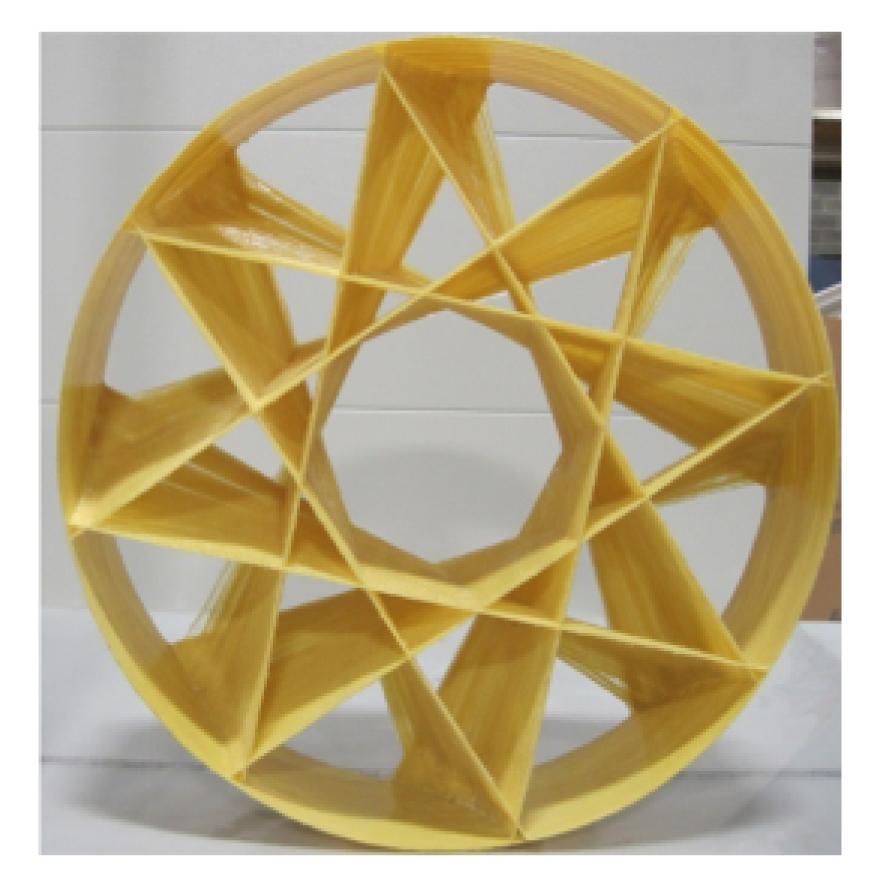
Due to the world’s increasing electricity demand and environmental concerns, a lot of research has been carried out and technologies developed to improve the thermal efficiency of power consumption in energy systems (Tuo et al., 2011; Tuo, 2012). Renewable and sustainable energy, including solar, wind, ocean, hydropower, and geothermal, has become more and more attractive due to its lower impact on the environment than conventional energy (Kamat, 2007). Finding reliable and alternative energy resources is one of the most important issues facing people in the 21st century. Renewable energy resources are constantly available and environmentally friendly. Marine current energy is increasingly being recognized as a major source to be exploited for sustainable generation of electric power. In 2003, the world’s first commercial-scale marine current turbine (MCT) with a rated power of 300 kW was successfully installed by the Marine Current Turbines Ltd. and IT-Power in England (Ponta and Jacovkis, 2008). Although MCT’s rotors are driven by the marine current in the same way that windmill rotors are driven by the wind, the marine environment is considerably more hostile than the low level atmospheric conditions experienced by wind turbines (Yang and Shu, 2012). The axial thrust on an MCT and its support structure is larger than that on wind turbines due to the higher density of sea water. Corrosion is also a serious problem which has to be considered in MCTs (Bahaj and Myers, 2003). Thus, there is an increased interest in the use of composites as alternative materials because of their high strength-to-weight ratios and high corrosion resistance (Marsh, 2004). A novel manufacturing approach similar to filament winding is able to produce a composite material marine current turbine (CMMCT) in a variety of patterns (Fig. 1). The manufacture of these high-performance and light weight composite rotors is rapid and inexpensive (Wang and Müller, 2011; Wang et al., 2011a; 2011b). The new rotors have significant advantages over conventional designs due to their high resistance to corrosive salt water, extremely light weight and high stability in construction (Wang and Müller, 2011). The use of a diffuser as an option to increase the extracted power has been studied numerically and experimentally. Results have shown that the extracted power is larger than that of wind or water turbines without a duct (Gilbert and Foreman, 1983; Lawn, 2003; Setoguchi et al., 2004; Kirke, 2006; Ponta and Jacovkis, 2008; Gaden and Bibeau, 2010).
Fig.1 Prototype of a composite material rotor
In this study, a numerical approach was performed using computational fluid dynamics (CFD) in a free stream of water to examine the performance of a bare and a ducted CMMCT. Two main characteristics, static torque and extracted power, of these two types of turbines, were calculated and compared at different rotation speeds in a free stream with various hydrodynamic flow conditions.
2. Numerical method and computational modeling
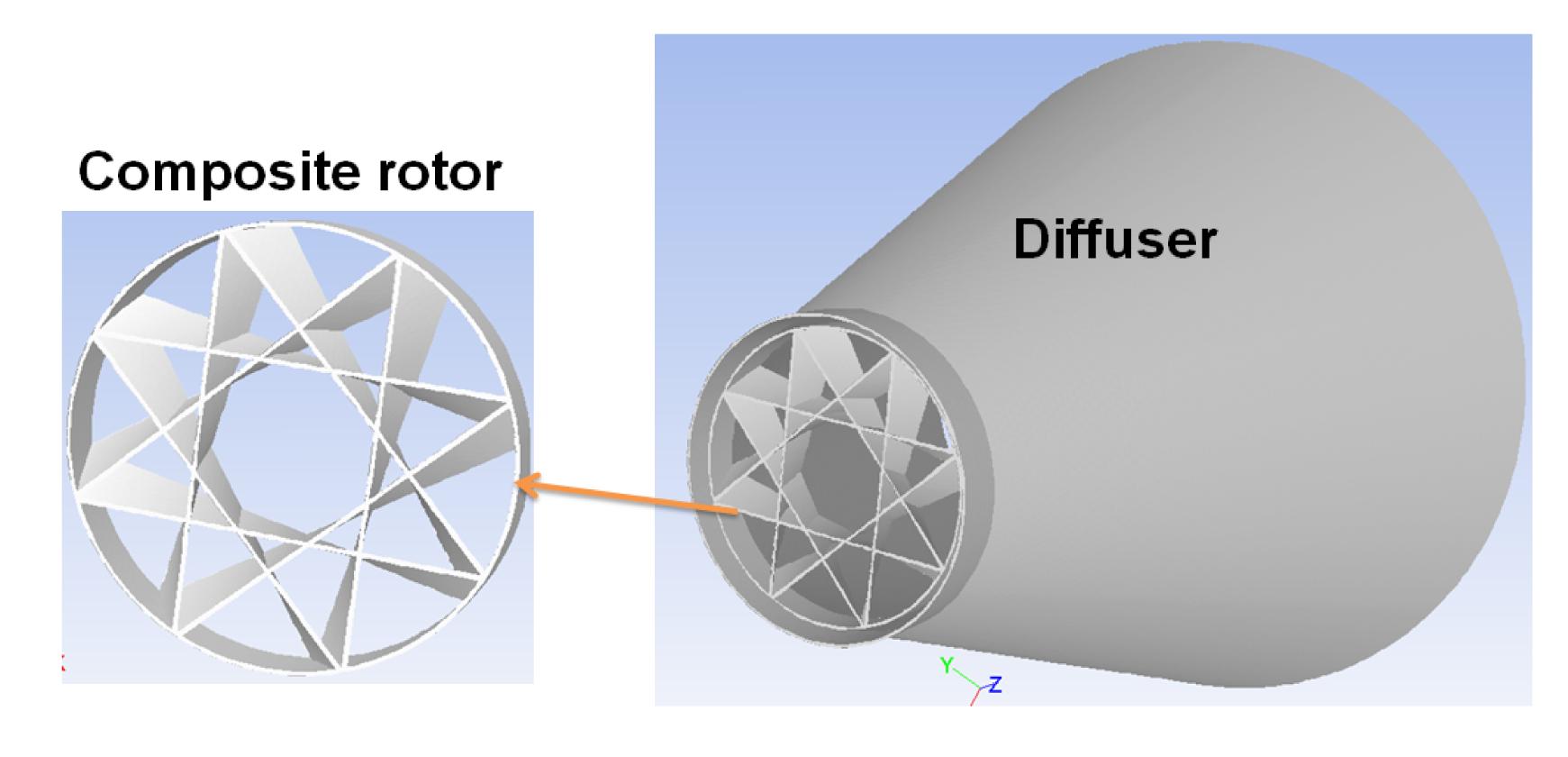
A bare and a ducted turbine were modeled and analyzed. They were placed in a square cross section of side 15 m, and length 30 m (Fig. 2). The diffuser outlet diameter defines the ratio of the diffuser outlet area to the turbine area, which was the primary variable of interest. Due to the limited space and manufacturing cost, it is important to know the relationship between the diffuser size and its performance benefits. Gaden and Bibeau (2010) found that increasing the area ratio gave increases in power initially but at higher ratios had only minimal benefits. This is expected intuitively due to separation and drag behavior. In this study, a ducted turbine with a diffuser diameter of 4.5 m and an angle of 20° was considered in the same computational domain as a bare turbine.
Fig.2 Modeling of a CMMCT
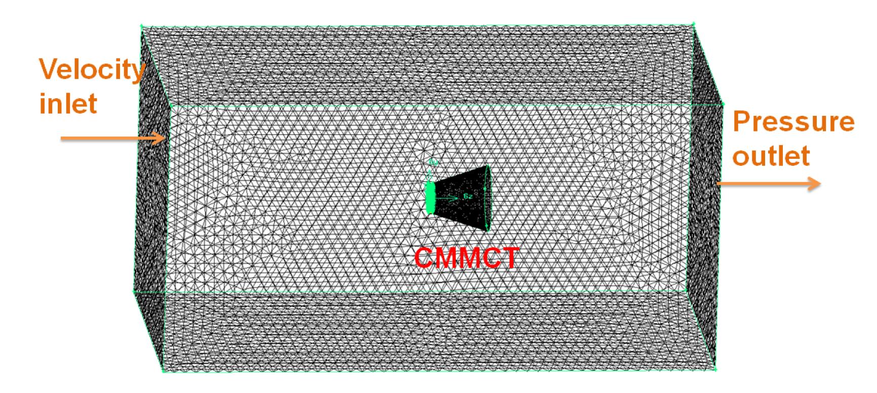
For the computational domain, unstructured 3D tetrahedral meshing was employed due to its flexibility when solving geometries (Fig. 3). To accurately simulate the flow in a turbine passage, further mesh refinement of the turbine was required (Fig. 4). We started the CFD procedure with a coarse meshing and gradually refined it until the variability in the results (such as the torque) was smaller than an acceptable error indicating that the results had converged. Finally, a coarser grid giving the same torque as the finer grid was accepted for further calculations. After checking the grid independence, a grid size was chosen with 2 247 226 elements.
Fig.3 3D meshing of the computational domain
Fig.4 Meshing refinement of the computational domain in the diffuser (a) and turbine (b)
CFD is based fundamentally on the governing equations of fluid dynamics. They represent mathematical statements of the conservation laws of physics, where the following physical laws are adopted (Wang et al., 2012):
1. Mass is conserved for the incompressible fluid at steady state as
,
where ui is the fluid velocity, and xi is the location.
2. For the fluid analysis of the entire turbine at steady state, the incompressible Navier-Stokes equations were used in the following form:
,
where ρ, p and ui denote fluid density, mean static pressure and fluid velocity, respectively.
The standard κ-ε model was utilized for the turbulence model in the CFD calculation. The model is the oldest model and the one most checked model against experimental measurements (Wang and Müller, 2011). A wall function is required to treat the wall conditions correctly but the meshing might be coarser near the wall. Near wall meshing quality could be controlled by monitoring the y+ value. The rotation flow was modeled using the multiple reference frame (MRF) approach, where the fluid zone is divided into two separate regions: a stationary zone, which is related to the free stream, and another zone related to the moving zone, close to the rotating turbine (Bridgeman and Parsons, 2009). The governing equations were solved in the absolute frame and discretized by the finite volume technique provided by the ANSYS FLUENT software. The standard pressure correction technique semi-implicit method for pressure-linked equations (SIMPLE scheme) was used for solution, and the second order upwind scheme was utilized in FLUENT (Shaaban and Abdel Hafiz, 2012). For setting the boundary conditions, the computational domain inlet was applied at uniform velocity, while at the outlet a constant pressure condition was utilized. The symmetry boundary condition was used for the side walls of the computational domain due to the minimally disruptive nature of the flow. No slip wall conditions were considered for the turbine blades. For the CFD calculation, the main input variables were inlet velocity, turbulence level and dimensional scale of turbulence. The output was the momentum (torque) applied to the rotor, being the result of integration of the pressure distribution on the surfaces of the rotor. In this study, the mass flow rate and momentum change for a convergence tolerance of 10−4 were monitored, as with these criteria the calculated results did not change significantly compared to those from a higher convergence level of 10−5.
3. Results and discussion
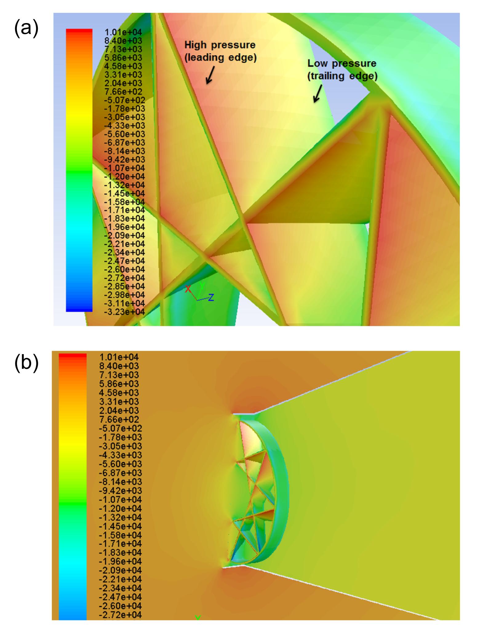
The extracted power can be represented by the product of the water flow through the turbine and the pressure drop across the turbine (Hansen et al., 2000). Figs. 5 and 6 show the static gage pressure (Pa) distribution on a bare CMMCT and on a ducted CMMCT in the same flow and rotation speed conditions. The pressure drop in the ducted CMMCT is larger than that in the bare CMMCT, which means that the extracted power is larger given the same hydrodynamic conditions.
Fig.5 Static pressure distribution on a bare CMMCT (unit: Pa)
Fig.6 Static pressure distribution on a ducted CMMCT in the same flow (a) and rotation speed (b) conditions (unit: Pa)
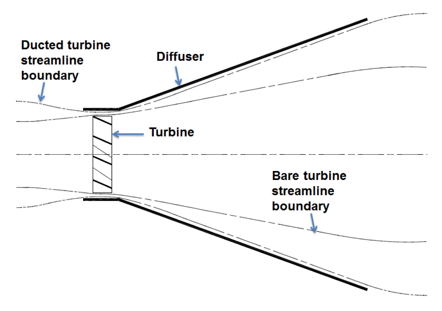
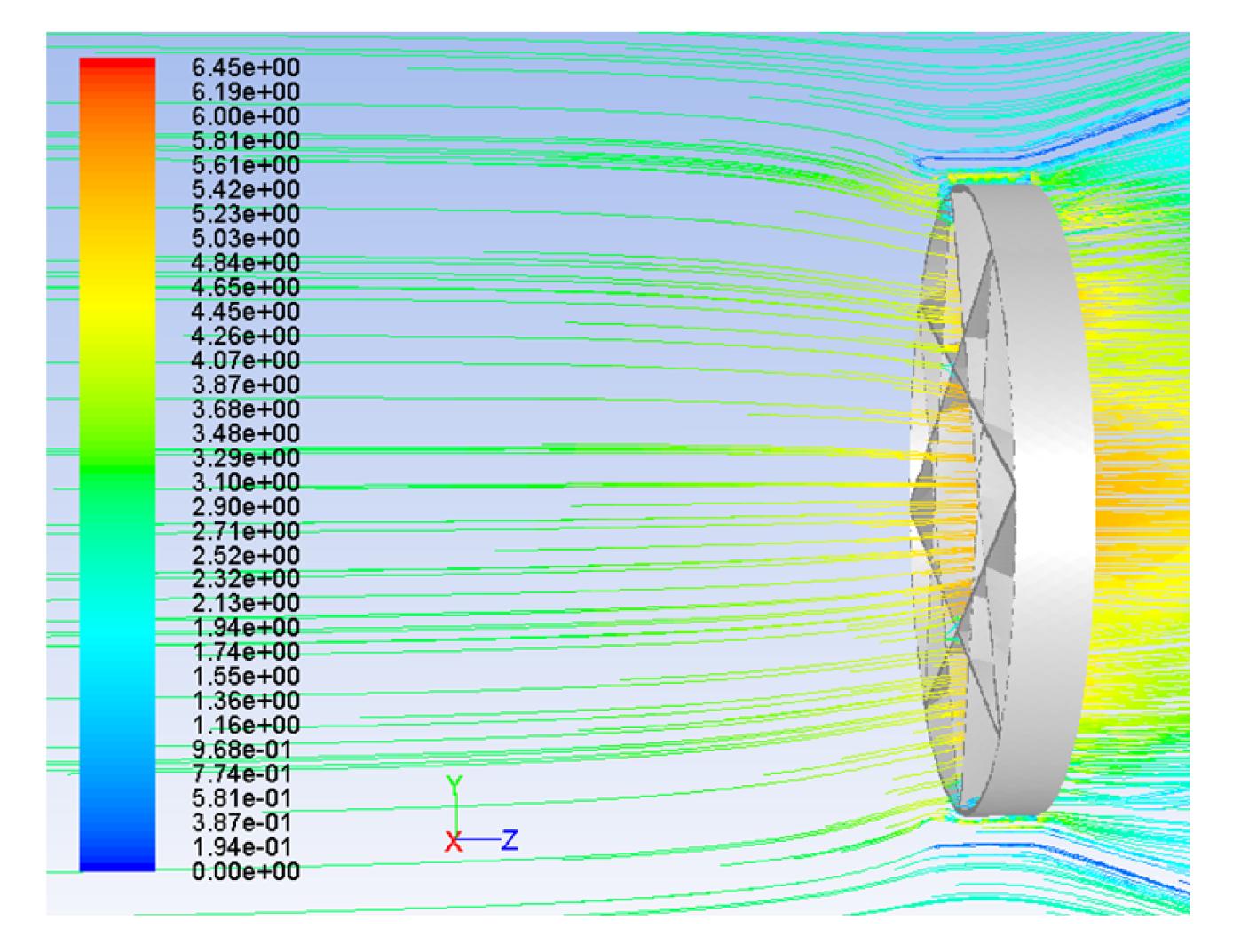
Cavitation occurs when the absolute value of the local pressure coefficient on the blades, Cp, is greater than the cavitation number, σv. Locally near the leading edge of the blades, the pressure on the suction side is reduced and in some conditions can reach the water evaporation pressure (at analyzed temperature), leading to formation of a cavitation bubble. Typically a cavitation bubble appears in the low pressure area just behind the leading edge on the suction side of the blades. However, due to rather high hydrostatic pressure near the devices under the water surface and the low load on the blades, the existence of cavitation in the analyzed case is not expected. For this designed geometry of CMMCT, the absolute value of the pressure coefficient Cp is below 2. Assuming a minimal water depth of 10 m and a water flow speed of 6.17 m/s, the cavitation number σv is estimated to be no lower than 4.6. Operation at such a high cavitation number prevents the development of sheet cavitation and dangerous effects of cloud and bubble cavitation. Also, the external shroud protects against the generation of vortex cavitation characteristics at the free blade’s tips (Wang and Müller, 2011). Fig. 7 shows a schematic of streamline through a turbine in open flow and through a ducted turbine. Correspondingly, a path line diagram of the inlet of a ducted CMMCT placed in a free flow speed of 3 m/s is presented in Fig. 8, where the streamline boundary is observed. From the streamline boundaries, we note that with the same pressure at the ducted turbine and at the bare turbine outlets, path lines are concentrated in the ducted turbine plane, which on the basis of the Bernoulli equation, indicates lower pressure and higher entry flow velocity (mass flow).
Fig.7 Streamline through a turbine in open flow and with a diffuser-augmented turbine
Fig.8 Path line diagram of a ducted turbine with a free flow speed of 3 m/s. The color contour indicates the flow velocity in m/s
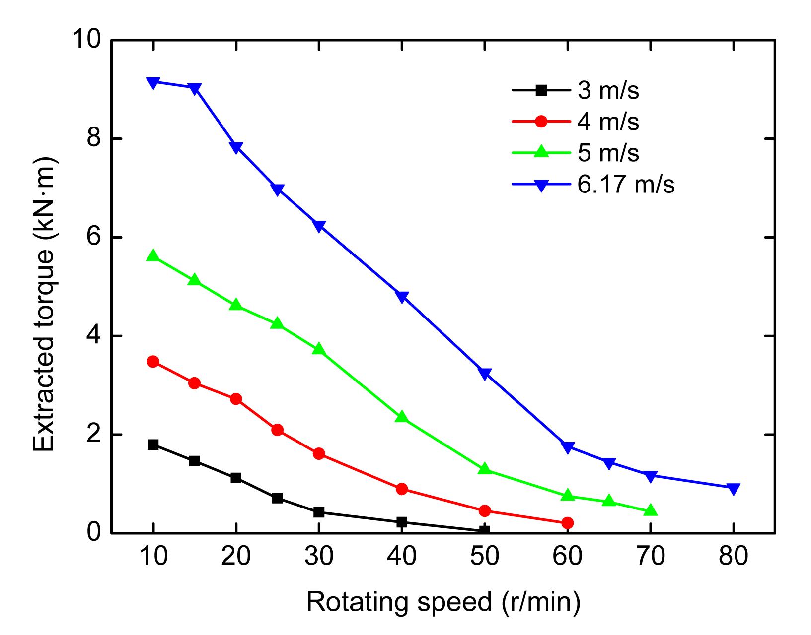
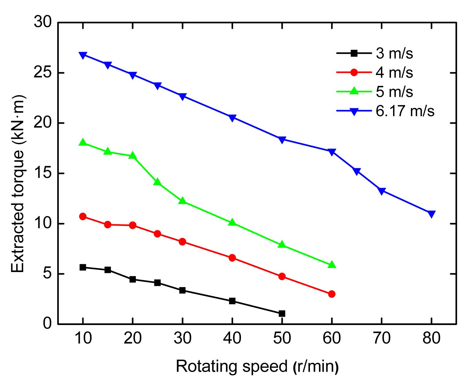
The simulation results for extracted torque and power for a CMMCT and a ducted CMMCT in various hydrodynamic flow conditions, at water flow speeds of 3 m/s, 4 m/s, 5 m/s and 6.17 m/s were simulated according to the available capability of the experimental system used for testing. Fig. 9 shows the variation in the extracted torque of a bare turbine in a free stream of water with various hydrodynamic flow conditions (water flow and turbine rotational speeds). The extracted torque decreases with increasing rotation speed and with decreasing flow speed. Similarly, Fig. 10 plots the extracted torque of a ducted CMMCT, where the maximum extracted torque is three times larger than that from the bare CMMCT.
Fig.9 Extracted torque of a bare turbine showing variation with inlet flow and rotating speed
Fig.10 Extracted torque of a ducted turbine showing variation with inlet flow and rotating speed
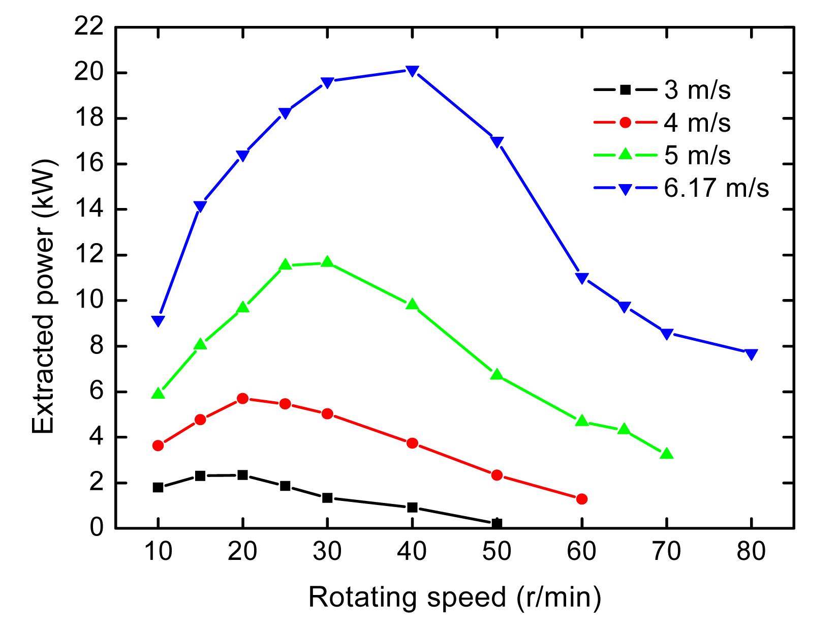
From Euler’s equation, the turbine’s extracted power is given by the multiplication of the extracted torque and the rotation speed (Dixon, 1998). Fig. 11 shows variation in the extracted power of a bare CMMCT in a free stream of water with various hydrodynamic flow conditions. The extracted power first increases with increasing turbine rotation speed, but after reaching the maximum power, it decreases with further increasing speed. Thus, to extract maximum power, a CMMCT should be operating at a suitable rotation speed. For a specific rotation condition, the power is dependent on the water flow speed, and increases with the water flow speed. Fig. 12 plots the variation in the extracted power of a ducted CMMCT in a free stream of water with various hydrodynamic flow conditions. At different flow speeds, the maximum extracted power of a ducted CMMCT is about three to four times larger than that of a bare CMMCT.
Fig.11 Extracted power of a bare turbine showing variation with inlet flow and rotating speed
Fig.12 Extracted power of a ducted turbine showing variation with inlet flow and rotating speed
4. Conclusions
A CMMCT, which has significant advantages over traditional designs, has been developed and investigated numerically. A substantial improvement in turbine performance is achieved by the placement of a duct to concentrate the energy in the water. A suitably shaped diffuser can draw in flow from a larger area and increase the available pressure drop across the turbine. The maximum extracted power of the ducted CMMCT is three to four times greater than the power extracted by a bare CMMCT of the same turbine area. The analysis results provide an insight into the hydrodynamic design and operation of a ducted CMMCT used to shorten the design period and improve technical performance. Future research will be directed towards optimizing the turbine’s performance in extracting ocean power by changing the number of blades and the size and angle of the diffuser. Moreover, an experimental setup and data acquisition system will be established to validate the simulation results.
References
[1] Bahaj, A.S., Myers, L.E., 2003. Fundamentals applicable to the utilisation of marine current turbines for energy production. Renewable Energy, 28(14):2205-2211.
[2] Bridgeman, J., Parsons, S., 2009. Computational fluid dynamics modelling of flocculation in water treatment: a Review. Engineering Applications of Computational Fluid Mechanics, 3:220-241.
[4] Gaden, D.L.F., Bibeau, E.L., 2010. A numerical investigation into the effect of diffusers on the performance of hydro kinetic turbines using a validated momentum source turbine model. Renewable Energy, 35(6):1152-1158.
[5] Gilbert, B.L., Foreman, K.M., 1983. Experiments with a diffuser-augmented model wind turbine. Journal of Energy Resources Technology, 105(1):46-53.
[6] Hansen, M.O.L., Srensen, N.N., Flay, R.G.J., 2000. Effect of placing a diffuser around a wind turbine. Wind Energy, 3(4):207-213.
[7] Kamat, P.V., 2007. Meeting the clean energy demand: nano-structure architectures for solar energy conversion. The Journal of Physical Chemistry C, 111(7):2834-2860.
[8] Kirke, B., 2006. Developments in Ducted Water Current Turbines. , Available from
,[Accessed on August, 2010],:
[9] Lawn, C.J., 2003. Optimization of the power output from ducted turbines. Proceedings of the Institution of Mechanical Engineers, Part A: Journal of Power and Energy, 217(1):107-117.
[10] Marsh, G., 2004. Tidal turbines harness the power of the sea. Reinforced Plastics, 48(6):44-47.
[11] Ponta, F.L., Jacovkis, P.M., 2008. Marine-current power generation by diffuser-augmented floating hydro-turbines. Renewable Energy, 33(4):665-673.
[12] Setoguchi, T., Shiomi, N., Kaneko, K., 2004. Development of two-way diffuser for fluid energy conversion system. Renewable Energy, 29(10):1757-1771.
[13] Shaaban, S., Abdel Hafiz, A., 2012. Effect of duct geometry on wells turbine performance. Energy Conversion and Management, 61:51-58.
[14] Tuo, H., 2012. Thermal-economic analysis of a transcritical Rankine power cycle with reheat enhancement for a low-grade heat source. International Journal of Energy Research, in press,:
[15] Tuo, H., Bielskus, A., Hrnjak, P., 2011. Effect of flash gas bypass on the performance of r134a mobile air-conditioning system with microchannel evaporator. SAE International Journal of Materials and Manufacturing, 4:231-239.
[16] Wang, J., Mller, N., 2011. Numerical investigation on composite material marine current turbine using CFD. Central European Journal of Engineering, 1(4):334-340.
[17] Wang, J., Piechna, J., Mller, N., 2011. A novel design and preliminary investigation of composite material marine current turbine. Archive of Mechanical Engineering, LVIII(4):355-366.
[18] Wang, J., Piechna, J., Yume, J.A.O., Mller, N., 2011. Stability analysis in wound composite material axial impeller. Proceedings of the Institution of Mechanical Engineers, Part C: Journal of Mechanical Engineering Science, 226(5):1162-1172.
[19] Wang, J., Piechna, J., Mller, N., 2012. A novel design of composite water turbine using CFD. Journal of Hydrodynamics, Ser B, 24(1):11-16.
[20] Yang, B., Shu, X.W., 2012. Hydrofoil optimization and experimental validation in helical vertical axis turbine for power generation from marine current. Ocean Engineering, 42:35-46.
Open peer comments: Debate/Discuss/Question/Opinion


Open peer comments: Debate/Discuss/Question/Opinion
<1>