Hu Zhang, Cun-lei Wang, Yong Zhang, Jun-yi Liang, Cheng-liang Yin. Drivability improvements for a single-motor parallel hybrid electric vehicle using robust controls[J]. Journal of Zhejiang University Science A, 2014, 15(4): 291-301.
@article{title="Drivability improvements for a single-motor parallel hybrid electric vehicle using robust controls", author="Hu Zhang, Cun-lei Wang, Yong Zhang, Jun-yi Liang, Cheng-liang Yin", journal="Journal of Zhejiang University Science A", volume="15", number="4", pages="291-301", year="2014", publisher="Zhejiang University Press & Springer", doi="10.1631/jzus.A1300356" }
%0 Journal Article %T Drivability improvements for a single-motor parallel hybrid electric vehicle using robust controls %A Hu Zhang %A Cun-lei Wang %A Yong Zhang %A Jun-yi Liang %A Cheng-liang Yin %J Journal of Zhejiang University SCIENCE A %V 15 %N 4 %P 291-301 %@ 1673-565X %D 2014 %I Zhejiang University Press & Springer %DOI 10.1631/jzus.A1300356
TY - JOUR T1 - Drivability improvements for a single-motor parallel hybrid electric vehicle using robust controls A1 - Hu Zhang A1 - Cun-lei Wang A1 - Yong Zhang A1 - Jun-yi Liang A1 - Cheng-liang Yin J0 - Journal of Zhejiang University Science A VL - 15 IS - 4 SP - 291 EP - 301 %@ 1673-565X Y1 - 2014 PB - Zhejiang University Press & Springer ER - DOI - 10.1631/jzus.A1300356
Abstract: For a single-motor parallel hybrid electric vehicle, during mode transitions (especially the transition from electric drive mode to engine/parallel drive mode, which requires the clutch engagement), the drivability of the vehicle will be significantly affected by a clutch torque induced disturbance, driveline oscillations and jerks which can occur without adequate controls. To improve vehicle drivability during mode transitions for a single-motor parallel hybrid electric vehicle, two controllers are proposed. The first controller is the engine-side controller for engine cranking/starting and speed synchronization. The second controller is the motor-side controller for achieving a smooth mode transition with reduced driveline oscillations and jerks under the clutch torque induced disturbance and system uncertainties. The controllers are all composed of a feed-forward control and a robust feedback control. The robust controllers are designed by using the mu synthesis method. In the design process, control-oriented system models that take account of various parameter uncertainties and un-modeled dynamics are used. The results of the simulation demonstrate the effectiveness of the proposed control algorithms.
Darkslateblue:Affiliate; Royal Blue:Author; Turquoise:Article
Article Content
1. Introduction
In recent decades, in response to air pollution, global warming, and the rapid depletion of the earth’s petroleum resources, the development of high-efficiency and clean transportation have been proposed. Automotive powertrain hybridization is one of the most promising technologies (Chan, 2002; Ehsani et al., 2009). For hybrid electric vehicles, based on energy management optimization (Xiong et al., 2009; Liang et al., 2013), the engine can operate primarily in the fuel-efficient regions and be shut off when needed to save energy. Regenerative braking can also improve fuel economy. For plug-in hybrid electric vehicles, the battery can be restored to full charge by connecting a plug to an external electric power source, which can greatly reduce the dependence on petroleum (Sheikhi et al., 2013). In addition to fuel savings, hybrid electric vehicles should also exhibit good drivability. Compared to conventional vehicles, drivability issues for hybrid electric vehicles are more severe because of the powertrain system configuration and unique system characteristics such as frequent engine starts and stops, engagement and disengagement of the clutch, and a quick motor torque response (Zhang et al., 2008; Hong et al., 2009). In a single-motor parallel hybrid electric vehicle, the engine should be started with the motor via the clutch when needed. Consequently, the clutch torque causes significant disturbance to the driveline, especially at the end of the clutch engagement process in which the clutch lockup causes a step torque disturbance. These disturbances can result in drivability problems including driveline oscillations and jerks which can cause discomfort for the passengers.
Previous studies have been conducted to improve vehicle drivability issues including the damping control of driveline oscillations for conventional vehicles, electric vehicles (EVs) and hybrid electric vehicles (HEVs) and smooth mode transition control for HEVs. In some previous studies, linear quadratic regulator (LQR) and H infinity controllers were proposed to damp driveline oscillations for conventional vehicles (Lefebvre et al., 2003; Templin and Egardt, 2009). Uncertainties in parameters such as vehicle mass were discussed in the design of an H infinity controller. However, the H infinity approach is more conservative than the mu synthesis method. A predictive controller was used to damp driveline oscillations for a conventional vehicle in which delays introduced by the controller area network (CAN) can be compensated (Caruntu et al., 2011a). In EV/HEVs, the driveline damping control is different from conventional vehicles because of the motor’s quick torque response. An LQG controller was designed to damp driveline oscillations for an electric vehicle (Amann et al., 2004). The mode transition control contains driveline damping controls and it is much more complicated. A parallel hybrid electric vehicle was considered to be a switched hybrid dynamical system, and hybrid control theory was used to design the mode transition controller (Koprubasi et al., 2007). However, the sensitivity of the control system to parametric uncertainties and time delays has not yet been studied. A model predictive control was applied to a parallel hybrid vehicle powertrain to achieve a smooth mode transition (Beck et al., 2005). However, the effect of time delays due to CAN communication has not yet been studied. A model transition control using a disturbance observer was proposed for a parallel hybrid electric vehicle (Kim et al., 2011), and the clutch torque and engine torque estimation errors were considered to cause primary disturbances. Additionally, some parameters in the powertrain model were assumed to be time-dependent, and an online identification method was used to estimate the parameters. A control system was designed for clutch-assisted engine starts in a parallel hybrid electric vehicle (He et al., 2010; Smith et al., 2011). The control system contains two parts: one part controls the clutch to spin up the engine, and the second part regulates the motor torque to compensate for the clutch torque induced disturbance. Additionally, proportional-integral-derivative controllers were used as a feedback control and the associated system uncertainties have not yet been studied. In this paper, robust controllers are designed using mu synthesis to achieve a smooth mode transition for a single-motor hybrid electric vehicle, and the system uncertainties and time delays are additionally considered.
This paper is organized as follows. The vehicle architecture of a single-motor parallel hybrid electric vehicle is introduced in Section 2. In Section 3, the control-oriented system models are developed. Then, based on the control-oriented system models, the design of robust controllers is discussed in Section 4 by using the mu synthesis method. In the design process, various parameter uncertainties and un-modeled dynamics are taken into account. Finally, detailed simulation results and analysis are described in Section 5, and the results indicate that the proposed control algorithm is capable of improving the drivability for a single-motor parallel hybrid electric vehicle during the mode transition under various system uncertainties and external disturbances.
2. Vehicle architecture
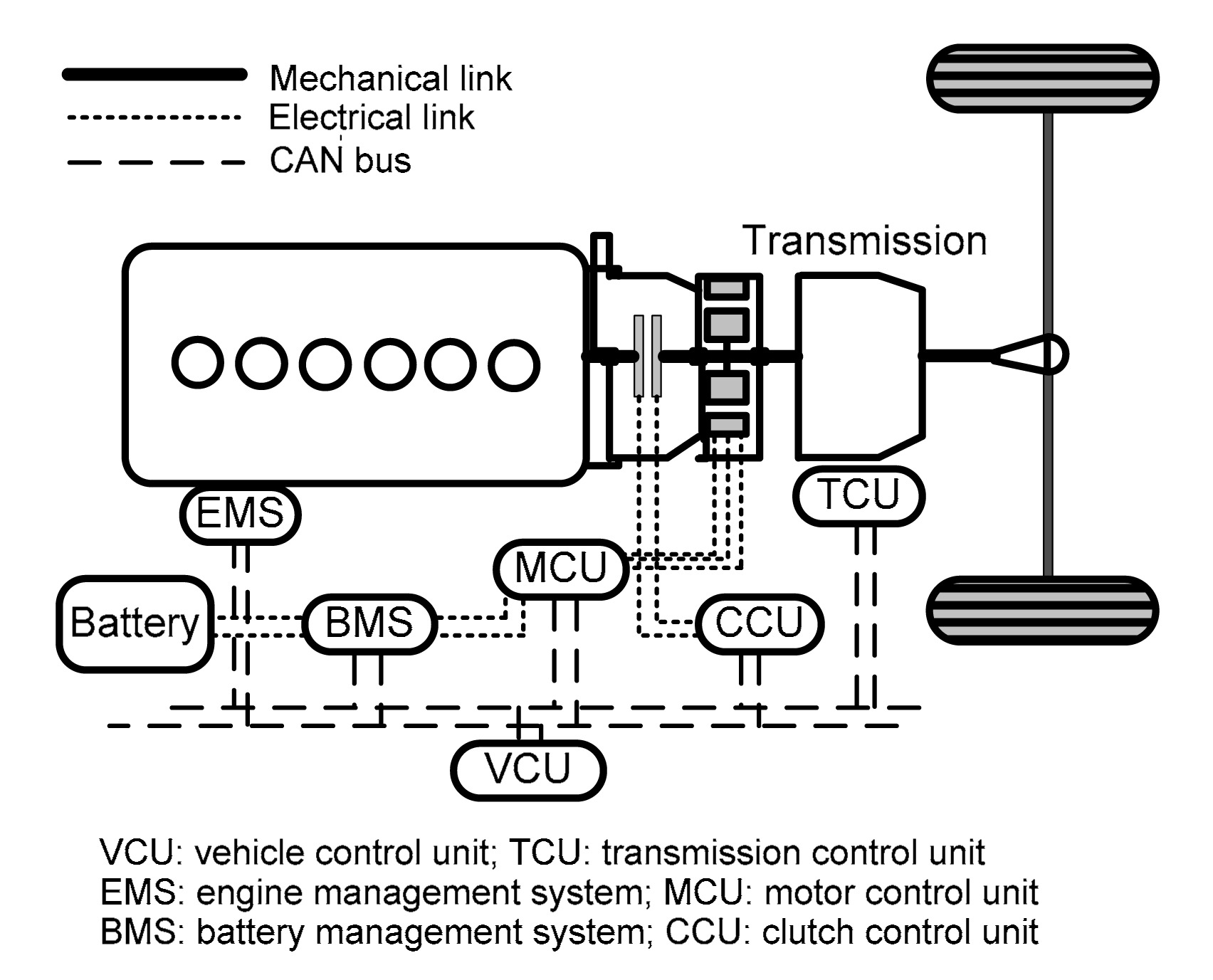
The single-motor parallel hybrid electric vehicle consists of a diesel engine, an electric motor, and an electronically controlled clutch, which is located between the engine and the motor to enable mode transitions by engaging or disengaging the clutch, as shown in Fig. 1. Under urban (reduced load) driving conditions or if the battery has a high state of charge, the vehicle operates in an electric drive mode. In this case, the clutch is disengaged, and the engine is shut off to save energy. Under highway (high load) driving conditions or if the battery has a low state of charge, the vehicle operates in engine or parallel drive mode with the clutch engaged. To perform this mode transition, the motor should start the engine and simultaneously propel the vehicle because this parallel hybrid electric vehicle contains only a single motor.
Fig.1 Architecture of the single-motor parallel hybrid electric vehicle
3. System modeling
To develop the proposed control algorithm to improve drivability, an accurate and control-oriented system model is required. The model structure is shown in Fig. 2.
Fig.2 Structure of the single-motor parallel hybrid electric vehicle model
Based on the model structure, the equations of a dynamic system can be derived as follows.
1. Disengaged and slipping mode
where J1 is the engine inertia, J2 is the combined inertia of the motor and transmission at the motor shaft, and J3 is the combined inertia of the wheels and the effective vehicle inertia acting on the wheels. ω1 is the engine shaft speed, ω2 is the motor shaft speed, and ω3 is the wheel angular speed. b1, b2, and b3 are damping coefficients for the axles. Te is the engine torque, Tc is the clutch torque, Tm is the motor torque, Ts is the half-shaft torque, and Tl is the load torque. r is the gear ratio.
2. Engaged mode
3. Half-shaft torque model
where ks is the equivalent stiffness of the entire haft shaft/assembly, bs is the equivalent damping coefficient of the tires and the bearings, and θs is the torsional angle of the shaft.
4. CAN delay model
As mentioned above, the CAN communication will introduce time delays to the system. These time delays are not constant and will change according to the CAN bus load. Based on the robust control design methodology, the time delays in the control system in this study are all treated as system uncertainties. First, the upper bound of the time delay should be determined. The following equation can be used to determine the upper bound of the time delay induced by the CAN communication (Herpel et al., 2009; Caruntu et al., 2011b).
,
where j is the priority of the node for which the upper bound is calculated, l denotes the maximum frame length, RCAN is the rate of the CAN, and ci is the cycle length of the ith priority message.
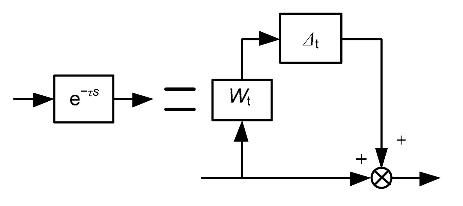
After obtaining the upper bound of the time delay, a multiplicative uncertain model can be constructed to represent the time delay, as shown in Eq. (5) and Fig. 3.
,
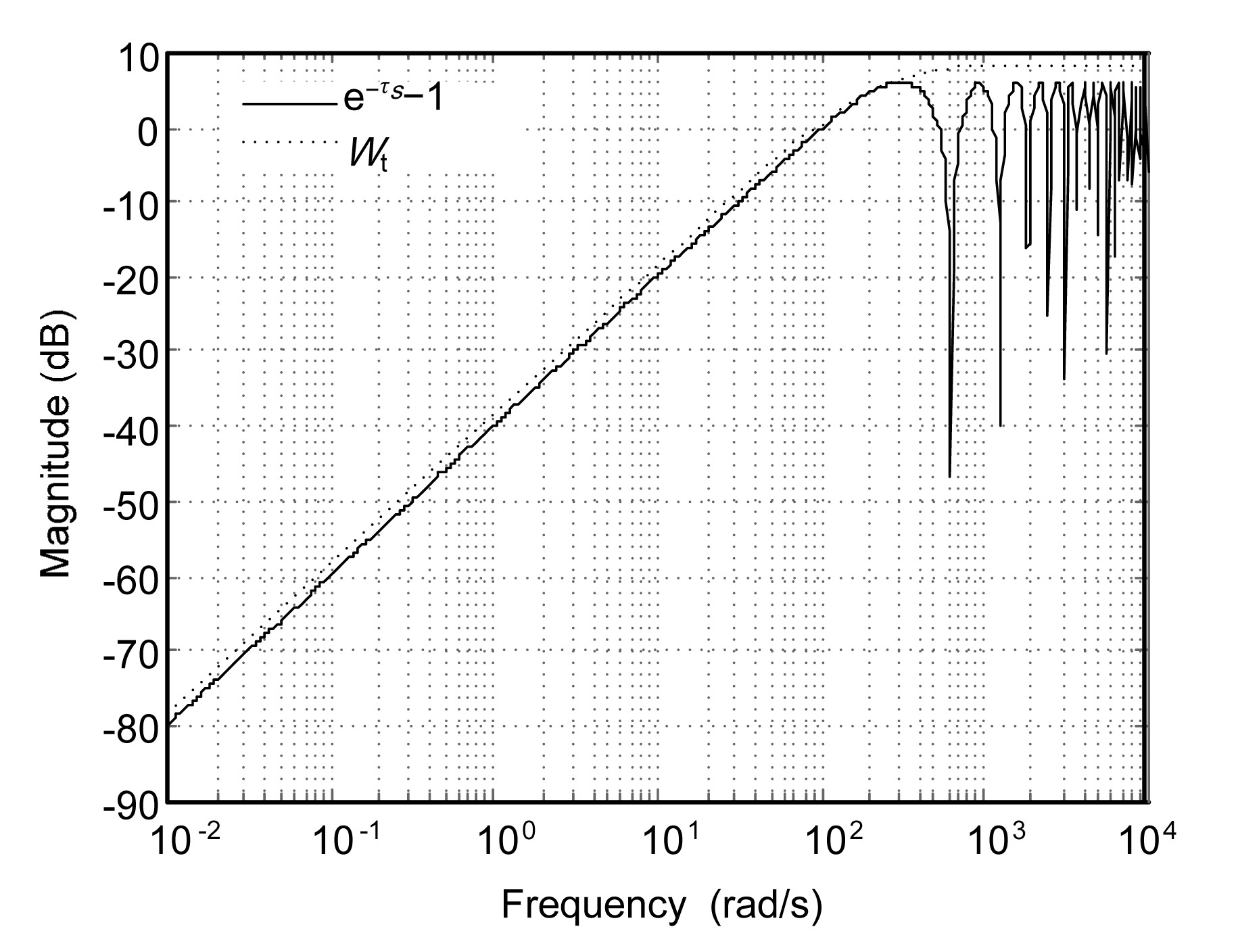
where Wt is the upper bound of and Δt represents the uncertainty (Fig. 4).
Fig.3 Time delay model
Fig.4 Bode diagram of Wt and e−τs−1
4. Control design
To achieve smooth transition from electric drive mode to engine/parallel drive mode, two controllers should be designed. The first controller is the engine-side controller for engine cranking/starting and speed synchronization. The second controller is the motor-side controller for achieving a smooth mode transition with reduced driveline oscillations and jerks under the clutch torque induced disturbance and system uncertainties.
4.1. Engine side control
4.1.1. Engine crank/start
The single-motor parallel hybrid electric vehicle contains only a single motor, and consequently, if the vehicle switches from electric drive mode to engine/parallel drive mode, then the engine should be started with the motor via the clutch. Before the engine reaches a specified speed (approximately 800 r/min), the fuel injection system will not be active, and the engine will not have positive torque output. Because of engine-resistant torque oscillations at low speed, the engine speed feedback control will cause clutch torque oscillations that can be transmitted to the driveline. Furthermore, there is no need for the engine to track a speed reference during this stage. As a result, a feed-forward control is applied by using a constant clutch torque command.
4.1.2. Engine speed synchronization
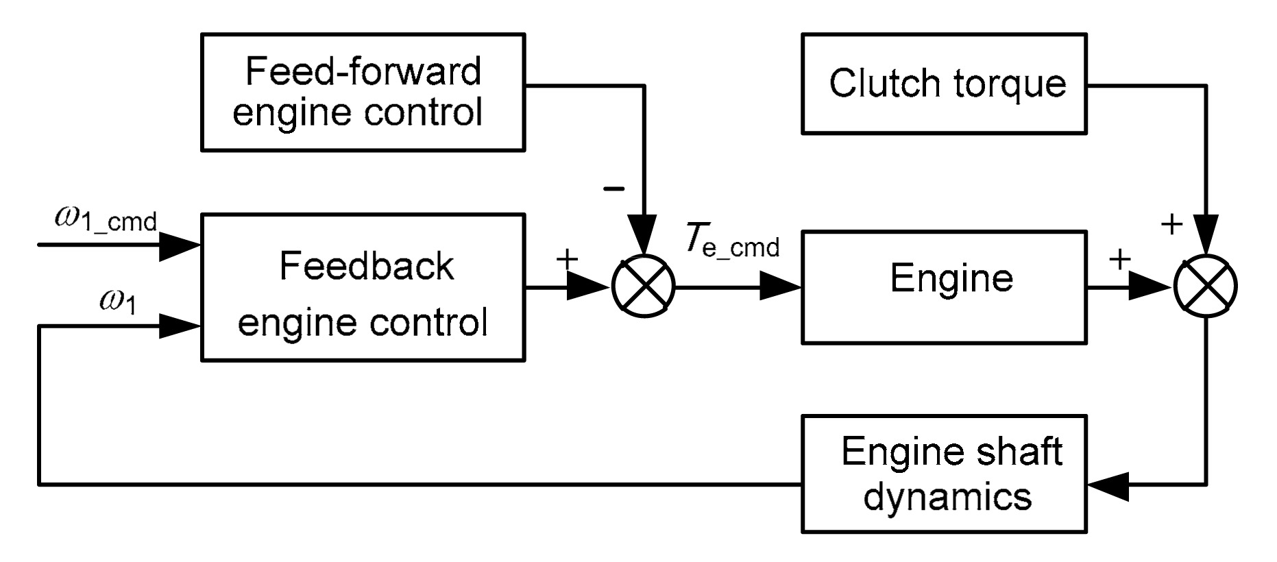
After the engine reaches the specified speed, the fuel injection system activates, and positive torque will be produced. At this time, the speed synchronization stage is active, and the engine speed should be synchronized with the motor speed by using a clutch torque and engine torque. The clutch torque control is still feed-forward. According to the system model, the clutch torque is the disturbance for the engine torque. Therefore, the engine torque control contains two parts as shown in Fig. 5: one part is the feed-forward engine torque control which is used to compensate the clutch torque by using the estimated clutch torque, and the other part is the robust feedback controller Ke that will be described in the following section. By using a feed-forward engine torque control with the estimated clutch torque, some of the anticipated clutch torque can be compensated. However, because of the clutch torque estimation error and transient effects, the disturbance cannot be completely compensated. Therefore, there is a residual disturbance Tcd in the control system after the feed-forward control as shown in Fig. 6.
Fig.5 Control structure for engine side control
Fig.6 Interconnected engine side control system for the mu synthesis
4.1.3. Robust control design
A controller Ke was designed to track the engine speed reference (the motor speed) with various system uncertainties and disturbances. The interconnected system for robust control design is shown in Fig. 6. The plant was constructed based on the system model. The engine torque dynamic was considered and modeled as a first-order dynamic as shown in Eq. (6).
.
As described in Section 3, the CAN communication-induced delay was modeled as a multiplicative uncertainty model, which is given by
.
The magnitude and frequency content of the engine speed command is scaled by Wcmd1,
where ω1max is the maximum engine speed command.
For adequate engine speed tracking, the closed-loop system is required to respond like a well-damped second-order system Gideal1, which is constructed as
,
where ωn1 is the desired natural frequency and ς1 is the desired damping ratio.
The magnitude of the clutch torque estimation error-induced disturbance and engine speed measurement noise are scaled by Wcd and Wn1, respectively. Tcd_max is the maximum disturbance torque, and n1max is the maximum measurement noise.
The performance weighting function Wp1 is constructed as
,
where e1max is the maximum engine speed tracking error.
Wact1 which is used to limit the maximum feedback control magnitude is constructed as
,
where u1max is the maximum feedback control magnitude.
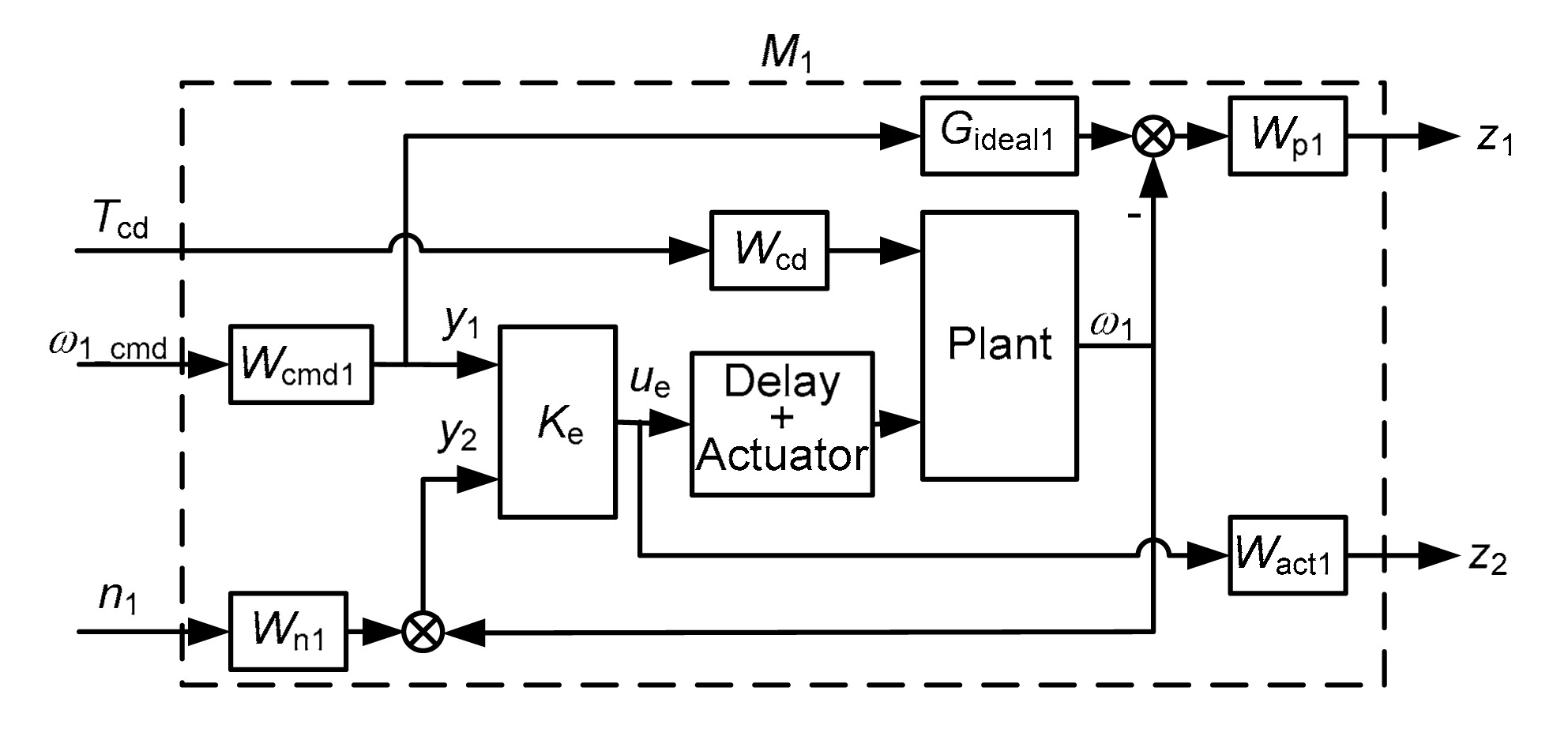
The diagram in Fig. 6 can also be represented by using linear fraction transform (LFT) (Skogestad and Postlethwaite, 2001) as shown in Fig. 7. The interconnected system has three inputs, Tcd, ω1_cmd, n1, and two outputs, z1, z2, where z1 represents the weighted engine speed tracking error, and z2 represents the weighted feedback control effort. The controller Ke has two inputs: the engine speed command y1 and the measured engine speed y2. Based on the mu synthesis method, the controller Ke can be obtained by using a D-K iteration (Balas et al., 2001) to calculate the minimized structured singular value μ1 as shown in Eq. (13). FL(M1, Ke) is the lower LFT of the engine side control system.
.
Fig.7 LFT of engine side control system for the mu synthesis
4.2. Motor side control
4.2.1. Control structure
From the engine side control, we observed that during the mode transition from electric drive mode to engine/parallel drive mode, the clutch torque should be used to start the engine, which causes a significant disturbance to the driveline. To achieve a smooth mode transition, two types of control methods can be used. The first control method is the feed-forward control, which is given by
where Tm_cmd is the motor torque command, Tm_v is the motor torque used to propel the vehicle, and Tc_est and Te_est are the estimated clutch torque and the engine torque, respectively. In the slipping mode, the clutch torque causes the disturbance in the motor side control, which is compensated through the feed-forward control based on the estimated clutch torque, as shown in Eq. (14). If the clutch is engaged, then the engine torque, engine shaft inertia, and damping effect will be added to the driveline, which should also be compensated through the feed-forward control, as shown in Eq. (14). Because of inaccuracies in the estimation, the disturbances cannot be completely compensated through the feed-forward control, and thus, the driveline oscillations and jerks will remain.
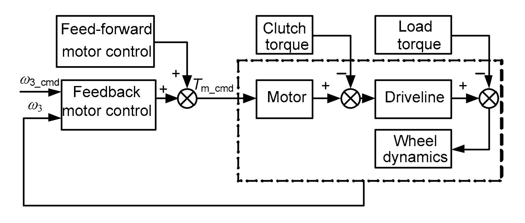
The second control method involves tracking the vehicle speed reference to achieve a smooth mode transition with reduced oscillations and jerks. The vehicle speed reference is obtained based on the assumption that vehicle acceleration is constant during mode transition. According to the system model, the clutch torque and load torque are two disturbances in the motor control. Therefore, the second type of control contains two parts as shown in Fig. 8: one part is the feed-forward motor torque control which is used to compensate for the clutch torque and load torque by using the estimated clutch torque and load torque, and the second part is the feedback controller that will be described in the following section.
Fig.8 Control structure for motor side control
The equation for the motor torque controller for vehicle speed tracking can be derived as follows:
where Tm_Km1 and Tm_Km2 are the feedback motor torque controls for the slipping and engaged modes, respectively, which can be obtained from the robust controllers Km1 and Km2 that will be described in the following section. Tc_est is the estimated clutch torque, and Tl_est is the estimated load torque. By using a feed-forward control with the estimated clutch torque and load torque, some of the anticipated clutch torque and load torque can be compensated. However, because of the clutch torque estimation error, load model inaccuracy, and transient effects, these two disturbances cannot be completely compensated. Therefore, there are two residual disturbances Tcd and Tld in the control system, as shown in Fig. 9.
Fig.9 Interconnected system for the robust control design of Km1
4.2.2. Robust control design
The design process for Km1 and Km2 is the same. The design process for Km1 is described as follows. The controller Km1 is used to track the vehicle speed with lower oscillations and jerks in the slipping mode. The interconnected system for robust control design is shown in Fig. 9. The plant is constructed based on the system model in which some parameter uncertainties are considered.
where the inertia J3 varies according to the vehicle mass. J30, ks0, and bs0 are nominal values for J3, ks, and bs, respectively. δJ3,δks, and δbs are uncertain variables which are real and satisfy the normalized bound,
.
The motor torque dynamic is modeled as a first-order transfer function, which is given by
.
The CAN communication-induced delay is modeled as a multiplicative uncertainty model.
.
The magnitude and frequency content of the vehicle speed command is scaled by Wcmd2,
where ω3max is the maximum vehicle speed command.
For an adequate vehicle speed tracking response, the closed-loop system is required to respond like a well-damped second-order system Gideal2, which is constructed as
,
where ωn2 is the desired natural frequency and ς2 is the desired damping ratio.
The magnitude of the clutch torque estimation error-induced disturbance, the load torque estimation error-induced disturbance, and the measurement noise are scaled by Wcd, Wld, and Wn2, respectively.
The performance weighting function Wp2 is constructed as
,
which weights the vehicle speed tracking error. Here, e2max is the maximum vehicle speed tracking error.
The performance weighting function Wp3 is constructed as
,
which penalizes the torsional angular velocity to reduce driveline oscillations. Here, e3max is the maximum torsional angular velocity.
Wact2 is used to limit the maximum feedback control magnitude, which is given by
,
where u2max is the maximum feedback control magnitude.
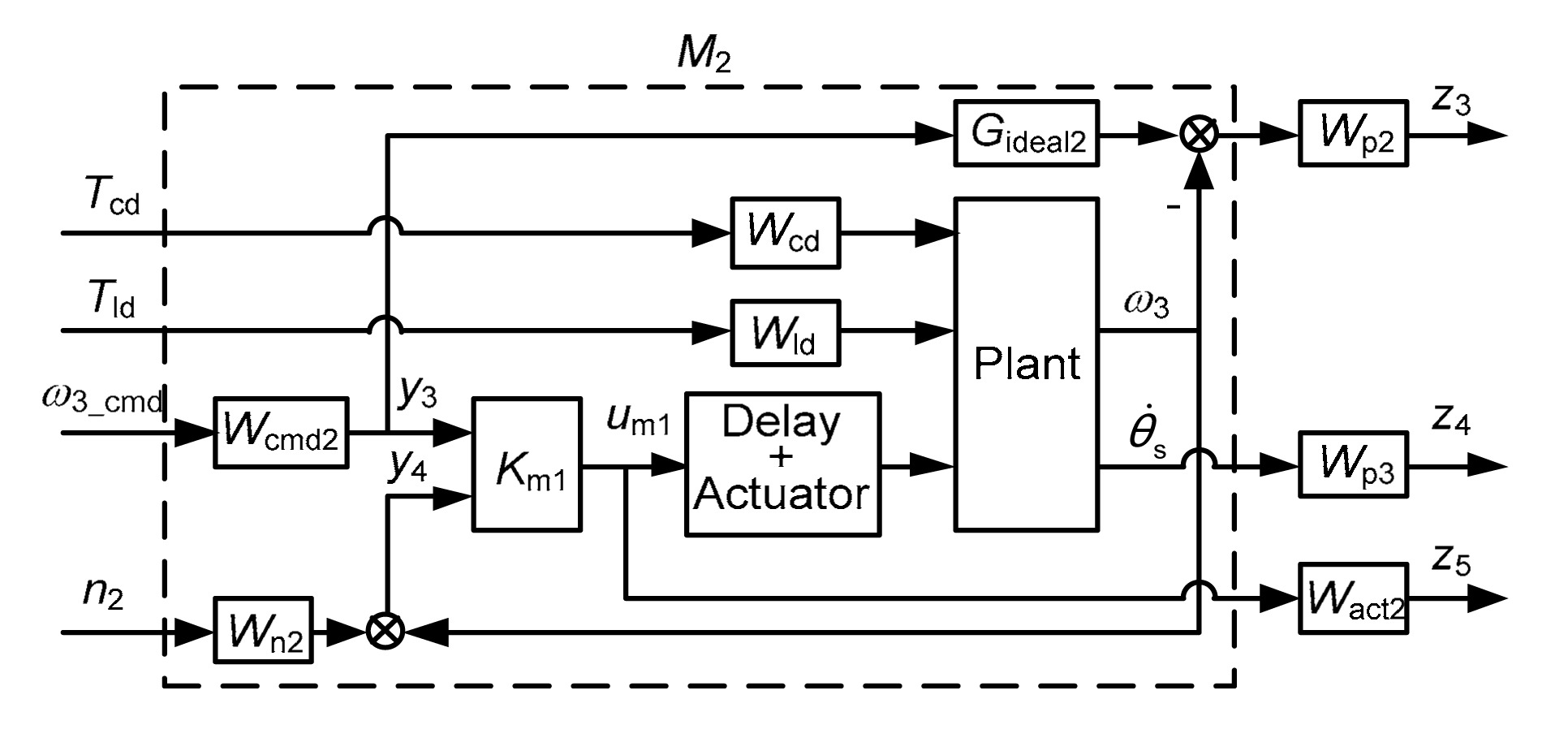
The diagram in Fig. 9 can also be represented by using an LFT as shown in Fig. 10. The interconnected system has four inputs, Tcd, Tld, ω3_cmd, n2, and three outputs, z3, z4, z5, where z3 represents the weighted vehicle speed tracking error, z4 represents the weighted torsional angular velocity, and z5 represents the weighted feedback control effort. The controller Km1 has two inputs: the vehicle speed command y3 and the measured vehicle speed y4. Based on the mu synthesis method, the controller Km1 can be obtained by using the D-K iteration to calculate the minimized structured singular value μ2 as shown in Eq. (26). FL(M2, Km1) is the lower LFT of motor side control system.
.
Fig.10 LFT of motor side control system for the mu synthesis
5. Simulation and analysis
Simulations were conducted to demonstrate the performance of the proposed controllers. The first simulation used the nominal system model to validate the nominal control performance. All of the parameters were set to their nominal values, and the CAN communication delays were neglected. The accuracies of the clutch torque estimation and vehicle load estimation were set at 90%.
The condition for the simulation was a mode transition from electric drive mode to engine drive mode, which included engine cranking/starting, speed synchronization, and clutch lockup. For a mode transition from electric drive mode to engine drive mode, the engine torque will gradually increase to meet the vehicle requirements, and the motor torque will gradually decrease to zero (or negative to cause the motor to work in a generator mode) after the clutch lockup.
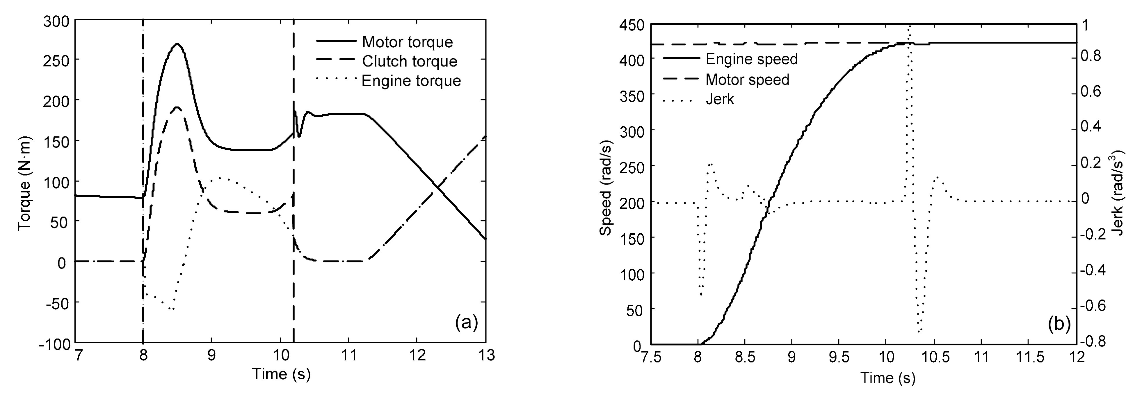
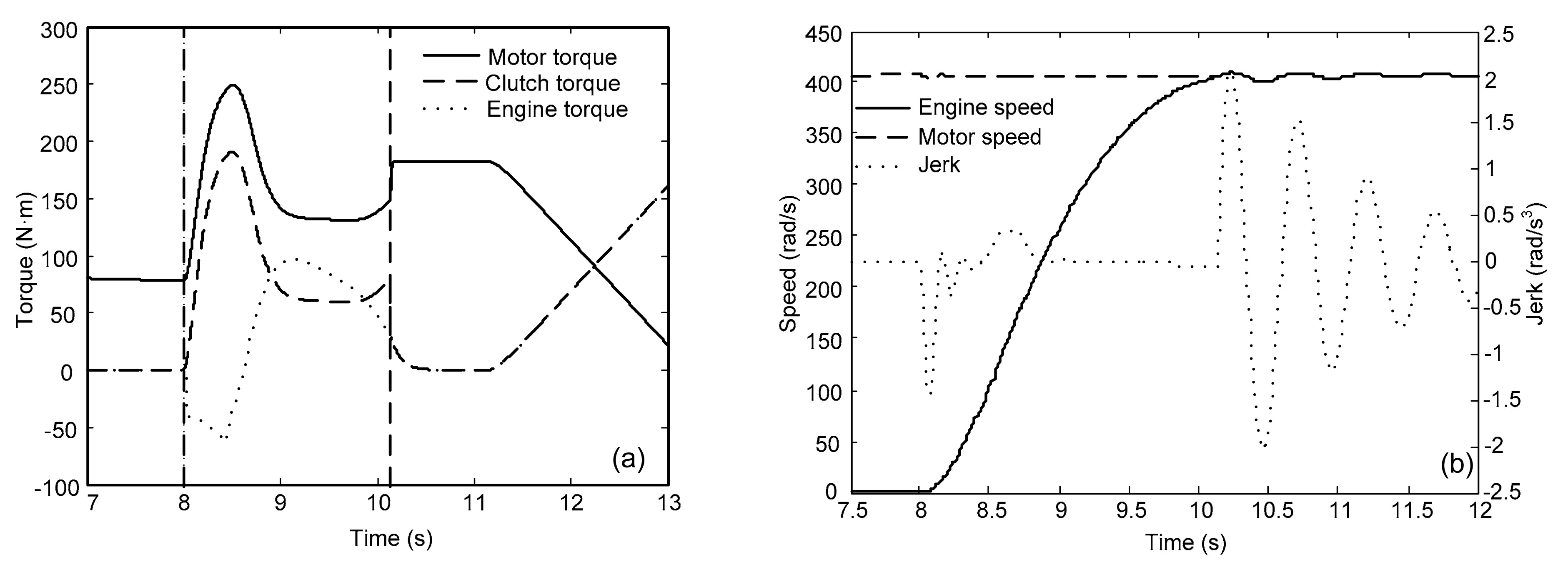
As shown in Fig. 11a, the engine started at 8 s with a constant vehicle speed. The clutch lockup occurred at approximately 10.2 s. At the beginning of the mode transition (8 s), the engine started with the clutch torque, which is a disturbance to the driveline. As a result, vehicle acceleration oscillations and jerks were caused. Under the control of the proposed motor side controller, which is composed of a feed-forward compensation and robust vehicle speed tracking control, the acceleration oscillations and jerks quickly dissipated as shown in Fig. 11b. At approximately 10.2 s, because of the clutch lockup, additional vehicle acceleration oscillations and jerks were observed, which also quickly dissipated using the proposed controls.
Fig.11 Nominal simulation results with proposed engine side control and proposed motor side control (a) Motor torque, clutch torque, and engine torque; (b) Engine speed, motor speed, and vehicle jerk
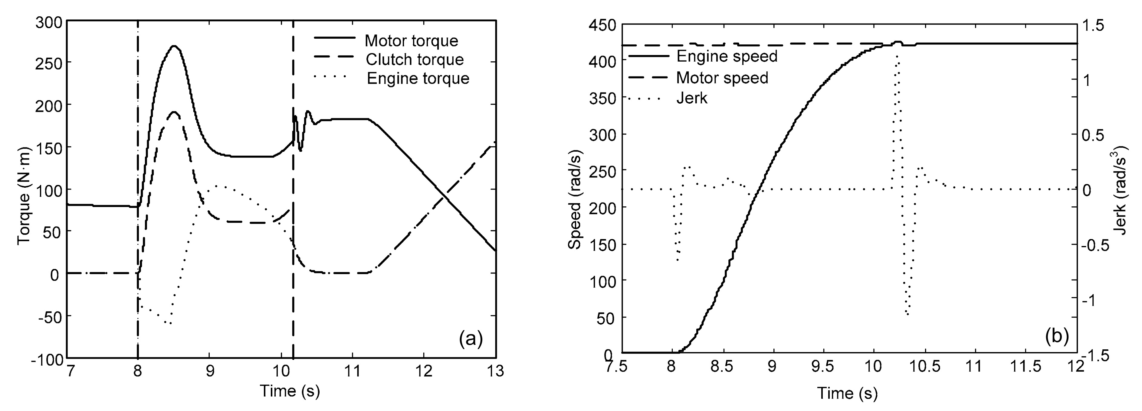
However, as shown in Fig. 12, the vehicle acceleration oscillations and jerks were relatively large using only a feed-forward motor side control, which was described in Section 4. Additionally, the vehicle acceleration oscillations and jerks remained for an extended period of time after the clutch lockup. This comparison indicates that the proposed controller was able to reduce torque disturbances and damp driveline oscillations/jerks. As the mode transitions from electric drive mode to engine drive mode, the engine torque gradually increases to meet the vehicle requirements, and the motor torque gradually decreases to zero after clutch lockup.
Fig.12 Nominal simulation results with proposed engine side control and feed forward motor side control (a) Motor torque, clutch torque, and engine torque; (b) Engine speed, motor speed, and vehicle jerk
Simulations were performed with various system uncertainties to validate the robustness of the control system. Uncertainty in the parameters (as previously described in the control design section) was taken into account. Additionally, the time-varying CAN communication-induced time delays were implemented by using variable transport delays in the simulations and the instantaneous delays were specified by random numbers whose upper bounds are 10 ms and lower bounds are 5 ms. Results of the simulation where the time delays were time-varying are shown in Fig. 13. The simulation where the time delays were set as constant delays (10 ms) was also conducted and the corresponding results are shown in Fig. 14. As shown in Figs. 13 and 14, vehicle acceleration oscillations and jerks slightly increased but were still within an acceptable range. The control system was robust to parameter uncertainties and time delays. In summary, the results indicate that the proposed controller was able to achieve a smooth mode transition with reduced driveline oscillations and jerks under the clutch torque induced disturbance and system uncertainties.
Fig.13 Simulation results with system uncertainties using proposed engine side control and proposed motor side control when the time delays are time-varying (a) Motor torque, clutch torque, and engine torque; (b) Engine speed, motor speed, and vehicle jerk
Fig.14 Simulation results with system uncertainties using proposed engine side control and proposed motor side control when the time delays are 10 ms (a) Motor torque, clutch torque, and engine torque; (b) Engine speed, motor speed, and vehicle jerk
6. Conclusions
The drivability issues for a single-motor parallel hybrid electric vehicle during mode transition were carefully analyzed and described. Because of the clutch torque-induced disturbance, vehicle drivability can be adversely affected during mode transition. Based on control-oriented system models, suitable controllers that used mu synthesis based robust feedback control and feed-forward controls were designed and had the ability to reduce torque disturbances and damp driveline oscillations/jerks during mode transitions. During the design process of a mu synthesis based robust feedback control, various parameter uncertainties and time delays were considered. The simulations that were performed demonstrated that the proposed controllers could achieve a smooth mode transition under the clutch torque induced disturbance and system uncertainties for a single-motor parallel hybrid electric vehicle. In future works, experimental validation will be conducted.
[1] Amann, N., Bocker, J., Prenner, F., 2004. Active damping of drive train oscillations for an electrically driven vehicle. Mechatronics, IEEE/ASME Transactions on, 9(4):697-700.
[2] Balas, G.J., Doyle, J.C., Glover, K., 2001. Mu-analysis and Synthesis Toolbox Users Guide, The MathWorks Inc,:
[3] Beck, R., Richert, F., Bollig, A., 2005. Model predictive control of a parallel hybrid vehicle drivetrain. , Proceedings of the 44th IEEE Conference on Decision and Control and European Control Conference CDC-ECC05, 2670-2675. :2670-2675.
[4] Caruntu, C.F., Balau, A.E., Lazar, M., 2011. A predictive control solution for driveline oscillations damping. , Proceedings of the 14th International Conference on Hybrid Systems: Computation and Control, 181-190. :181-190.
[5] Caruntu, C.F., Lazar, M., Di Cairano, S., 2011. Horizon-1 predictive control of networked controlled vehicle drivetrains. , 18th IFAC World Congress, 3824-3830. :3824-3830.
[6] Chan, C.C., 2002. The state of the art of electric and hybrid vehicles. Proceedings of the IEEE, 90(2):247-275.
[7] Ehsani, M., Gao, Y., Emadi, A., 2009. Modern Electric, Hybrid Electric, and Fuel Cell Vehicles: Fundamentals, Method and Design. CRC Press,Boca Raton, FL :1-2.
[8] He, Y., Bucknor, N., Smith, A., 2010. Modeling and drivability assessment of a single-motor strong hybrid at engine start. SAE Technical Paper, 2010-01-1440,:
[9] Herpel, T., Hielscher, K.S., Klehmet, U., 2009. Stochastic and deterministic performance evaluation of automotive CAN communication. Computer Networks, 53(8):1171-1185.
[10] Hong, J., Kim, S., Min, B., 2009. Drivability development based on cosimulation of AMESim vehicle model and Simulink HCU model for parallel hybrid electric vehicle. SAE Technical Paper, 2009-01-0725,:
[11] Kim, H., Kim, J., Lee, H., 2011. Mode transition control using disturbance compensation for a parallel hybrid electric vehicle. Proceedings of the Institution of Mechanical Engineers, Part D: Journal of Automobile Engineering, 225(2):150-166.
[12] Koprubasi, K., Westervelt, E.R., Rizzoni, G., 2007. Toward the systematic design of controllers for smooth hybrid electric vehicle mode changes. , Proceedings of the American Control Conference, New York, USA, 2985-2990. :2985-2990.
[13] Lefebvre, D., Chevrel, P., Richard, S., 2003. An H-infinity-based control design methodology dedicated to the active control of vehicle longitudinal oscillations. Control Systems Technology, IEEE Transactions on, 11(6):948-956.
[14] Liang, J.Y., Zhang, J.L., Zhang, X., 2013. Energy management strategy for a parallel hybrid electric vehicle equipped with a battery/ultra-capacitor hybrid energy storage system. Journal of Zhejiang University-SCIENCE A (Applied Physics & Engineering), 14(8):535-553.
[15] Sheikhi, A., Bahrami, S., Ranjbar, A.M., 2013. Strategic charging method for plugged in hybrid electric vehicles in smart grids; a game theoretic approach. International Journal of Electrical Power & Energy Systems, 53:499-506.
[16] Smith, A., Bucknor, N., Yang, H., 2011. Controls development for clutch-assisted engine starts in a parallel hybrid electric vehicle. SAE Technical Paper, 2011-01-0870,:
[17] Skogestad, S., Postlethwaite, I., 2001. Multivariable Feedback Control. John Wiley & Sons,Chichester :293-351.
[18] Templin, P., Egardt, B., 2009. An LQR torque compensator for driveline oscillation damping. , Control Applications (CCA) & Intelligent Control (ISIC), IEEE, 352-356. :352-356.
[19] Xiong, W.W., Zhang, Y., Yin, C.L., 2009. Configuration design, energy management and experimental validation of a novel series-parallel hybrid electric transit bus. Journal of Zhejiang University-SCIENCE A, 10(9):1269-1276.
[20] Zhang, J., Lu, X., Wang, L., 2008. A study on the drivability of hybrid electric vehicle. SAE Technical Paper, 2008-01-1572,:
Open peer comments: Debate/Discuss/Question/Opinion


Open peer comments: Debate/Discuss/Question/Opinion
<1>